In this tutorial, we will guide you through the process of creating an Asynchronous web server using ESP32 and Arduino IDE. To accomplish this, we’ll be using the ESPAsyncWebServer Library, specifically designed for the ESP32 Dev board in the Arduino IDE. With this web server, you’ll be able to control multiple LEDs connected to ESP32 GPIO pins concurrently. The server operates through HTTP GET requests, allowing data transfer from the user to the server seamlessly. Asynchronous web servers offer many advantages, as they can efficiently handle multiple connections simultaneously, enhancing the overall performance of your ESP32-based projects.
Asynchronous Web Server Introduction
What is Asynchronous Web Server?
An asynchronous web server is designed to handle XMLHttpRequests in a scalable and efficient way. Unlike traditional thread-based servers, which dedicate a separate thread to each client, the asynchronous server operates differently. In the traditional approach, there can be issues like blocking requests, where the server waits for resources to be freed up, causing delays and negatively affecting the client’s experience.
On the other hand, with an asynchronous server, there’s no need to create separate threads for each client’s request. Instead, it uses event-driven loops to process the requests from multiple clients simultaneously. This means that client requests don’t block each other, and they can be executed concurrently, leading to a smoother and more responsive user experience. Overall, an asynchronous server improves performance and enhances the way clients interact with the web server.
Asynchronous Web Server Library ESP32
In this tutorial, we will use the ESPAsyncWebServer library to build Asynchronous Web Server with ESP32 and Arduino IDE. Using an Async web server has many benefits as discussed on the official GitHub page of this library:
An Asynchronous server can handle multiple connections from different clients at the same time. When the request from the client is ready and parsed, a call is generated to notify the client. In case you have sent a response to the server, the server will start processing the response in the background and keep on taking your next requests. This allows the server to process individual and several requests with fast speed. The API is easy to use and supports HTTP Basic and Digest MD5 Authentication as default options along with Chucked Responses. The Asynchronous server is capable of handling any type of content and supports “continue 100” server code to enhance server client interactions. There are many plugins that enhance the user experience, we have listed some of them below:
- The Async WebSocket plugin offers its users to use different locations without requiring any extra servers or ports.
- Async EventSource plugin (Server-Sent Events) ensures smooth delivery of events to the browser.
- The URL Rewrite plugin enables the users to conditionally or permanently rewrite URLs for flexible routing.
- The ServeStatic plugin is also quite helpful as it supports cache, Last-Modified headers, default index, and more to enhance user experience and content delivery.
- Another efficient tool of Asynchronous server is a simple template processing engine. This enables its users to efficiently handle different templates and manage dynamic content generation.
Installing ESPAsyncWebServer Libraries
The ESPAsyncWebServer library allows for easy web server creation in the Arduino IDE. The important feature of this library is its Asynchronous server. Using this library, we can easily set up an Asynchronous HTTP server. Another library that we will be using is AsyncTCP. This library is a dependency of the ESPAsyncWebServer library. Although we will not be using the AsyncTCP library in our code, it acts as a base for the ESPAsyncWebServer library and it will not work properly without the AsyncTCP library.
Arduino library manager does not provide these libraries by default. So we will have to manually download and install them in the Arduino IDE ourselves. We will use GitHub to download the respective libraries and then place them in the library folder of our Arduino IDE.
The links are provided below to access the libraries:
You can open these links and follow our tutorial to successfully integrate these libraries into your IDE. After opening the ESPAsyncWebServer library link we will have a webpage similar to the one shown below
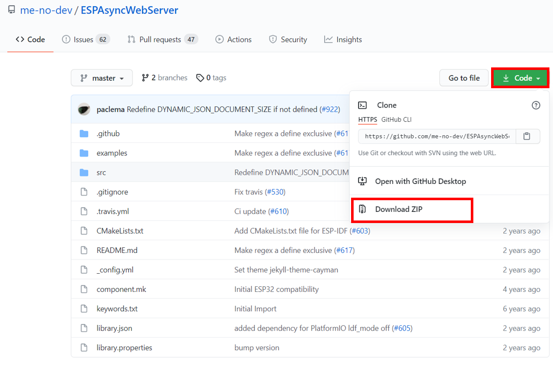
Now click on the code button (green) and select the Download Zip option from the drop down menu as highlighted in the above figure. Your Zip file will start downloading on your computer. After the downloading is complete we can move on to the installation process.
Methods for Installing Libraries in Arduino IDE
There are two methods for installing these libraries in Arduino IDE
- Method 1: Locate the zip file on your system. Now extract the zip file and make sure the folder renamed as ESPAsyncWebServer. Now repeat the process for AsyncTCP library and make sure to rename it as AsyncTCP. After renaming both library folders, copy these folders and paste them in Arduino Library folder.
This method is a bit tricky and if you are encountering issues and problems then do not fret, there is a second method and it is quite easy to follow along.
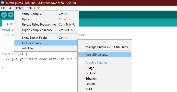
- Method 2: Open the Arduino IDE, go to Sketch > Include Library > Add .zip Library as shown in the figure above. Now the Arduino IDE will ask you to select the folder. Locate the zip folder and select it, then click the open option on the menu. The Arduino IDE will start extracting the zip folder automatically.
Make sure that you have installed both libraries in the Arduino IDE, before proceeding further along the tutorial.
ESP32 Asynchronous Web Server Project Overview
We will control 4 LEDs using the asynchronous web server. Our goal is to control the GPIO pin outputs of the ESP32 Dev board, so we will use LEDs for their simplicity and ease of use.
Required Components
These are the components required to build this project:
- ESP 32 Development Board x 1
- 5mm LED x 4
- 220 ohm resistors x 4
- Breadboard x 1
- Jumper Wires x 5
Schematic Diagram
Assemble the circuit by following the schematic diagram provided below.
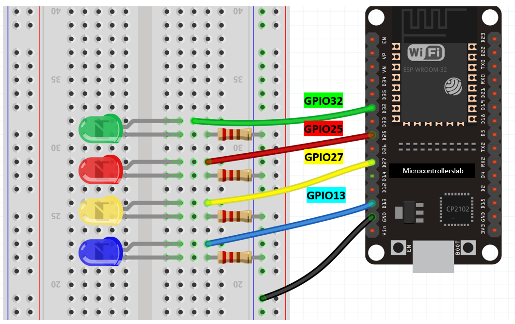
We have used LEDs of four different colors and connected their anode pins to four different GPIO pins. Later, in the program code, we will configure these GPIO pins as output pins and control them via a web server. We have grounded the cathode pins using 220-ohm resistors to ensure a safe current flow through the LEDs.
We have provided the connection pinout of ESP32 GPIO pins with the color of LEDs they will turn on, in the table below
| LED | GPIO PIN |
|---|---|
| Green | GPIO32 |
| Red | GPIO25 |
| Yellow | GPIO27 |
| Blue | GPIO13 |
Note: You can change these GPIO pins with any other GPIO pins of your preference, but you will need to change the respective GPIO pins in the sketch as well.
How Asynchronous Web Server Work?
In this section, we will explain the working of ESP32 Asynchronous web server. To understand the layout of the web server, you can check “Asynchronous Web Server Project Overview” section above.
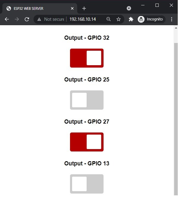
The webpage consists of a title “ESP32 WEB SERVER” and 4 toggle buttons in a column. These toggle buttons can slide back and forth, hence they can represent the LOW and HIGH states of GPIO pins based on their position. In case the LED is off, when the toggle button is pressed, it will turn on and the toggle button will slide to the right and turn red. This represents the HIGH state of the GPIO pin. Then, when the red toggle switch is pressed, the button will slide to the left and turn grey. This will represent the LOW state of the GPIO pin, and the LED will turn OFF. Each of the toggle buttons will be associated with a specific GPIO pin.
We have demonstrated the working of the toggle switch in the figure below.

Asynchronous Web Server LED Control Part
Let us look at an example of GPIO pin 32 to understand the mechanism of controlling GPIO with toggle buttons. In the above figure, the grey button indicates the LOW output state of the GPIO pin. When the toggle button is pressed, it will turn red. At the same time, the server will create an HTTP GET request. This HTTP request will have the following format: “/update?output=32&state=1”. The ESP32 will read this request and change the state of GPIO 32 from 0 to 1, indicating the change from LOW to HIGH, and the LED will turn on.
Similarly, when the red toggle button is pressed again, it will turn grey, and another HTTP GET request will be made on the web server. This time, the HTTP request will have the following format: “/update?output=32&state=0”. Once again, the ESP32 will read this request, but this time it will change the state of GPIO 32 from 1 to 0, meaning the change from HIGH to LOW, and the LED connected to GPIO 32 will turn off.
ESP32 AsyncWebServer Arduino Sketch
Open your Arduino IDE and create a new file. Now you can copy the code given below in that file and upload it to the ESP32 Dev board.
// Importing necessary libraries
#include <WiFi.h>
#include <AsyncTCP.h>
#include <ESPAsyncWebServer.h>

// Setting network credentials
const char* ssid = "REPLACE_WITH_YOUR_SSID";
const char* password = "REPLACE_WITH_YOUR_PASSWORD";

const char* input_parameter1 = "output";
const char* input_parameter2 = "state";

// Creating a AsyncWebServer object
AsyncWebServer server(80);


const char index_html[] PROGMEM = R"rawliteral(
<!DOCTYPE HTML><html>
<head>
  <title>ESP32 WEB SERVER</title>
  <meta name="viewport" content="width=device-width, initial-scale=1">
  <link rel="icon" href="data:,">
  <style>
    html {font-family: Arial; display: inline-block; text-align: center;}
    p {font-size: 3.0rem;}
    body {max-width: 600px; margin:0px auto; padding-bottom: 25px;}
    .switch {position: relative; display: inline-block; width: 120px; height: 68px}
    .switch input {display: none}
    .slider {position: absolute; top: 0; left: 0; right: 0; bottom: 0; background-color: #ccc; border-radius: 6px}
    .slider:before {position: absolute; content: ""; height: 52px; width: 52px; left: 8px; bottom: 8px; background-color: #fff; -webkit-transition: .4s; transition: .4s; border-radius: 3px}
    input:checked+.slider {background-color: #b30000}
    input:checked+.slider:before {-webkit-transform: translateX(52px); -ms-transform: translateX(52px); transform: translateX(52px)}
  </style>
</head>
<body>
  <h2>ESP32 WEB SERVER</h2>
  %BUTTONPLACEHOLDER%
<script>function toggleCheckbox(element) {
  var xhr = new XMLHttpRequest();
  if(element.checked){ xhr.open("GET", "/update?output="+element.id+"&state=1", true); }
  else { xhr.open("GET", "/update?output="+element.id+"&state=0", true); }
  xhr.send();
}
</script>
</body>
</html>
)rawliteral";

// Replaces placeholder with button section in your web page
String processor(const String& var){
  //Serial.println(var);
  if(var == "BUTTONPLACEHOLDER"){
    String buttons = "";
    buttons += "<h4>Output - GPIO 32</h4><label class=\"switch\"><input type=\"checkbox\" onchange=\"toggleCheckbox(this)\" id=\"32\" " + outputState(32) + "><span class=\"slider\"></span></label>";

    buttons += "<h4>Output - GPIO 25</h4><label class=\"switch\"><input type=\"checkbox\" onchange=\"toggleCheckbox(this)\" id=\"25\" " + outputState(25) + "><span class=\"slider\"></span></label>";

    buttons += "<h4>Output - GPIO 27</h4><label class=\"switch\"><input type=\"checkbox\" onchange=\"toggleCheckbox(this)\" id=\"27\" " + outputState(27) + "><span class=\"slider\"></span></label>";

   buttons += "<h4>Output - GPIO 13</h4><label class=\"switch\"><input type=\"checkbox\" onchange=\"toggleCheckbox(this)\" id=\"13\" " + outputState(13) + "><span class=\"slider\"></span></label>";

    return buttons;
  }
  return String();
}

String outputState(int output){
  if(digitalRead(output)){
    return "checked";
  }
  else {
    return "";
  }
}

void setup(){
  // Serial port for debugging purposes
  Serial.begin(115200);

pinMode(32,OUTPUT);
digitalWrite(32, LOW);
pinMode(25, OUTPUT);
digitalWrite(25, LOW);
pinMode(27, OUTPUT);
digitalWrite(27, LOW);
pinMode(13, OUTPUT);
digitalWrite(13, LOW);


  // Connect to Wi-Fi
  WiFi.begin(ssid, password);
  while (WiFi.status() != WL_CONNECTED) {
    delay(1000);
    Serial.println("Connecting to WiFi");
  }

  // Print ESP Local IP Address
  Serial.println(WiFi.localIP());

  // Route for root / web page
  server.on("/", HTTP_GET, [](AsyncWebServerRequest *request){
    request->send_P(200, "text/html", index_html, processor);
  });

  // Send a GET request to <ESP_IP>/update?output=<inputMessage1>&state=<inputMessage2>
  server.on("/update", HTTP_GET, [] (AsyncWebServerRequest *request) {
    String inputMessage1;
    String inputMessage2;
    // GET input1 value on <ESP_IP>/update?output=<inputMessage1>&state=<inputMessage2>
    if (request->hasParam(input_parameter1) && request->hasParam(input_parameter2)) {
      inputMessage1 = request->getParam(input_parameter1)->value();
      inputMessage2 = request->getParam(input_parameter2)->value();
      digitalWrite(inputMessage1.toInt(), inputMessage2.toInt());
    }
    else {
      inputMessage1 = "No message sent";
      inputMessage2 = "No message sent";
    }
    Serial.print("GPIO: ");
    Serial.print(inputMessage1);
    Serial.print(" - Set to: ");
    Serial.println(inputMessage2);
    request->send(200, "text/plain", "OK");
  });

  // Start server
  server.begin();
}

void loop() {

}
How the Code Works
Importing Libraries
Firstly, we will import the necessary libraries. For this project, we are going to use three libraries, these are “WiFi.h”, “ESPAsyncWebServer.h” and “AsyncTCP.h”. Wifi.h is required to connect ESP32 to a wireless network, this is essential as ESP32 will be communicating with the web server purpose. The other two libraries are the ones that we have recently downloaded and installed in Arduino IDE. We will use them to build our Asynchronous HTTP web server.
// Importing necessary libraries
#include <WiFi.h>
#include <AsyncTCP.h>
#include <ESPAsyncWebServer.h>
Setting Network Credentials:
Next, we will create two global variables, one for the SSID and the other for the password. These variables will store our network credentials so, the ESP32 Dev board can connect to the wireless network.
Note: Replace both of these variables with your credentials to ensure a successful connection of ESP32 with the network.
// Setting network credentials
const char* ssid = "REPLACE_WITH_YOUR_SSID";
const char* password = "REPLACE_WITH_YOUR_PASSWORD";
Setting Input Parameters
Now we will pass two more global variables of type char. These will be the input parameters to pass on the URL. One parameter is the GPIO number which we will call “output” and the other is its state (1 or 0). Notice that both of these inputs will be in the form of a numerical number, here 0 will represent LOW and 1 will represent HIGH state of GPIO.
const char* input_paramter1 = "output";
const char* input_parameter2 = "state";
Creating the AsyncWebServer Object
The AsyncWebServer object will be used to set up the ESP32 web server. We will pass the default HTTP port which is 80, as the input to the constructor. This will be the port where the server will look for the requests.
AsyncWebServer server(80);Creating the Web Page
We will create the index_html variable to store the HTML text. Then we will start with the title of the web page. The <title> tag will indicate the beginning of the web page title and </title> tag will indicate the end of the web page title. In between these tags, we will specify “ESP32 WEB SERVER” which will be displayed in the browser’s title bar.
<title>ESP32 WEB SERVER</title>Next, we will create a meta tag to make sure our web server is available for all browsers e.g., smartphones, laptops, computers etc.
<meta name="viewport" content="width=device-width, initial-scale=1">CSS Styling Web Page
CSS stands for Cascading Style Sheets, this is used to give style to a simple webpage and make it visually attractive. This helps in engaging users to a web page.
To add a CSS file here we will include <style> head tag, this tag marks the beginning of the CSS code. Then we will change the display text to Arial and align everything to the center of the web page. The font size of the title is set to H2 heading and the font size of the paragraph is set to 3.0rem. Next we we will style the toggle button, so it changes color based on the transition position of the toggle button
<style>
    html {font-family: Arial; display: inline-block; text-align: center;}
    p {font-size: 3.0rem;}
    body {max-width: 600px; margin:0px auto; padding-bottom: 25px;}
    .switch {position: relative; display: inline-block; width: 120px; height: 68px}
    .switch input {display: none}
    .slider {position: absolute; top: 0; left: 0; right: 0; bottom: 0; background-color: #ccc; border-radius: 6px}
    .slider:before {position: absolute; content: ""; height: 52px; width: 52px; left: 8px; bottom: 8px; background-color: #fff; -webkit-transition: .4s; transition: .4s; border-radius: 3px}
    input:checked+.slider {background-color: #b30000}
    input:checked+.slider:before {-webkit-transform: translateX(52px); -ms-transform: translateX(52px); transform: translateX(52px)}
</style>
HTML Web Page Body
The next step will be to define the HTML web page body. This will go inside the tags which mark the beginning and the ending of the script. This part will include the heading of the web page and the buttons. We will include the heading of our webpage inside the tags and it will be the same as that of the web browser title i.e., ESP32 WEB SERVER.
<h2>ESP32 WEB SERVER</h2>Creating Sliding Buttons
Then, we will define the buttons on our web page. We have buttons of two colors, red when the GPIO state is 1 and grey when the GPIO state is 0. So we will use a placeholder to monitor the correct GPIO states. %BUTTONPLACEHOLDER% will be used as the placeholder which will help us in creating the buttons.
We will use JavaScript to create a function which checks for the correct toggle feature of our sliding buttons through an if else statement. It will create the HTTP GET request whenever a button will be slid over inside the if statement. The element id will correspond to the GPIO pin number associated with the button.
<script>function toggleCheckbox(element) {
  var xhr = new XMLHttpRequest();
  if(element.checked){ xhr.open("GET", "/update?output="+element.id+"&state=1", true); }
  else { xhr.open("GET", "/update?output="+element.id+"&state=0", true); }
  xhr.send();
}
</script>
Processor () function
Inside the processor() function, we will replace the placeholder (%BUTTONPLACEHOLDER%) and build the buttons. This will occur whenever the web page will be accessed and if the placeholder is found inside the HTML script. As you can see, we will build four buttons but you can easily increase/decrease the number of buttons by adding/deleting the buttons section. The buttons variable will be of the type string and we will pass an empty string at first. Then, we will concatenate the HTML text for the buttons according to the current output state (1 or 0) of the button and build it accordingly (red or grey).
String processor(const String& var)
{

  if(var == "BUTTONPLACEHOLDER")
{
    String buttons = "";
    buttons += "<h4>Output - GPIO 32</h4><label class=\"switch\"><input type=\"checkbox\" onchange=\"toggleCheckbox(this)\" id=\"32\" " + outputState(32) + "><span class=\"slider\"></span></label>";

    buttons += "<h4>Output - GPIO 25</h4><label class=\"switch\"><input type=\"checkbox\" onchange=\"toggleCheckbox(this)\" id=\"25\" " + outputState(25) + "><span class=\"slider\"></span></label>";

    buttons += "<h4>Output - GPIO 27</h4><label class=\"switch\"><input type=\"checkbox\" onchange=\"toggleCheckbox(this)\" id=\"27\" " + outputState(27) + "><span class=\"slider\"></span></label>";

   buttons += "<h4>Output - GPIO 13</h4><label class=\"switch\"><input type=\"checkbox\" onchange=\"toggleCheckbox(this)\" id=\"13\" " + outputState(13) + "><span class=\"slider\"></span></label>";

    return buttons;
  }
  return String();
}
outputState() function
We will also define another function of type string named ‘outputState.’ This will take in the output of the buttons as a parameter, and through an if-else statement, it will check if the GPIO is ON or not. To accomplish this, we will use a simple digitalRead() function. If the GPIO is indeed ON, then it will return the string ‘checked’; otherwise, an empty string will be returned. The toggle switch will act as an input type, which we will specify as ‘checkbox.’ Every time the value of the checkbox changes, an “onchange” event will occur. This will call a toggleCheckbox() function to access the unique ID associated with each GPIO pin.
String outputState(int output){
  if(digitalRead(output)){
    return "checked";
  }
  else {
    return "";
  }
}
Setup() function
Inside the setup() function, we will open a serial connection at a baud rate of 115200. In the pinMode() function, we will pass the GPIO pins as parameters to configure them as output pins. We will initialize all the pins to a LOW state at the time of boot, which means all the LEDs will be OFF.
Serial.begin(115200);

pinMode(32,OUTPUT);
digitalWrite(32, LOW);
pinMode(25, OUTPUT);
digitalWrite(25, LOW);
pinMode(27, OUTPUT);
digitalWrite(27, LOW);
pinMode(13, OUTPUT);
digitalWrite(13, LOW);
Configuring WIFI
The following section of code will connect our ESP32 board with the local network whose network credentials we already specified above. Once the connection is established, the ESP32 board will print the IP Address on the serial monitor. This will help us to make a request to the server.
WiFi.begin(ssid, password);
while (WiFi.status() != WL_CONNECTED) {
  delay(1000);
  Serial.println("Connecting to WiFi");
}

Serial.println(WiFi.localIP());
Handling Requests (ESP32 side)
The next step will be to handle the requests received by the ESP32 module. We will check for two parameters in the request which we already specified in the code: the output and the state. These are saved in the variables: ‘input_parameter1’ and ‘input_parameter2’. These values will be saved in new variables named ‘inputMessage1’ which will contain the GPIO pin, and ‘inputMessage2’ which will contain the state of the GPIO pin.
if (request->hasParam(input_parameter1) && request->hasParam(input_parameter2)) {
  inputMessage1 = request->getParam(input_parameter1)->value();
  inputMessage2 = request->getParam(input_parameter2)->value();
digitalWrite(inputMessage1.toInt(), inputMessage2.toInt());
These will then get printed on the serial monitor. Also, the send() method will be used to return the HTTP response. It takes in three parameters. The first parameter is the response code which we will specify as 200. It is the HTTP response code for ok. The second parameter is the content type of the response which we will specify as “text/plain” and the third parameter is the actual message which we will be sent as the HTTP response. This is set as “OK”. The arrow operator will be used to call the send method on the AsyncWebServerRequest object.
  Serial.print("GPIO: ");
  Serial.print(inputMessage1);
  Serial.print(" - Set to: ");
  Serial.println(inputMessage2);
  request->send(200, "text/plain", "OK");
Initiating Connection
To start the server, we will call the begin() on our server object.
server.begin();loop() function
We don’t require any continuous function handling, so in this case, our loop() function is empty. All of the server functions are event-driven, and there is no need to call any function continuously.
void loop() {

}
Demonstration
Press the Enable/Reset button after uploading the sketch to ESP32 Dev board.

In your Arduino IDE, open up the Serial Monitor and you will be able to see the IP address of your ESP32 module.

Now copy this address into a web browser and press enter. The web server will look something like this:
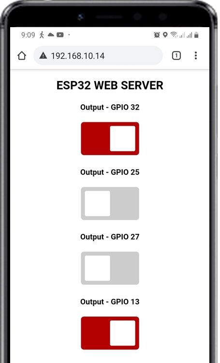
Now you can click on the buttons to toggle their state and change the output of GPIO pins of ESP32 connected to the LEDs respective to the title of the button. We can easily control all 4 LEDs using these toggle buttons. When the GPIO pin state changes after clicking the toggle button, the ESP32 will receive the HTTP GET request, and at the same time, the serial monitor will also print the GPIO pin’s current state on the screen. The web page will contain all the updated GPIO states according to the color of the buttons: GPIO HIGH > RED button and GPIO LOW > GREY button.
If you want to make this web server password protected, you can read this post on HTTP authentication:
Conclusion
In this guide, we have learned how to create an asynchronous web server through which we could control multiple outputs from the ESP32 development board. We also learned how to handle multiple client requests concurrently, boosting performance, and enhancing user experience. We provided an example of how to control LEDs.
You may also like to read these interesting ESP32 projects:
- WebSocket Server using ESP32 and SPIFFS
- ESP32 Web Server in Arduino IDE: Control LEDs
- ESP32 Web Server with SPIFFS (SPI Flash File System)
- ESP32 web server control relay and 220 volt lamp
- ESP32 BMP180 Web Server using Arduino IDE
- ESP32 Web Server Control Servo motor with Arduino IDE
- ESP32 static/fix IP address
- ESP32 soft access point web server in Arduino IDE
- Interface DHT11/DHT22 with ESP32 and display values on Web Server
- Accessing ESP32 web server from anywhere in the world ( ESP8266 compatible)
Do you have an example like this that uses esp idf framework instead of Arduino?
Hi,
Currently, we do not have any tutorial with the esp-idf framework. But we have started working to create tutorials with esp-idf.
Is there a way to have this same functionality but without needing to know the IP address? For example, if I take my ESP32 to another location, the IP address will be different, so I will need to connect to the serial monitor to see it, is there a way to avoid this?
This may help you:
https://microcontrollerslab.com/esp32-static-fix-ip-address/