The triac firing angle control circuit is designed to control the flow of AC power from the input supply to the load by changing the average voltage across the load. In this project, the triac firing angle is controlled to regulate the amount of power flowing to the load. The firing angle control circuit is designed using analog electronic components such as operational amplifiers, resistors, and capacitors. Zero-crossing detection, step-down transformer, rectifier, comparator, and ramp generator are the basic components of the firing angle control circuit for a triac. Triacs have many applications in power electronics, especially in AC voltage control circuits.
What is Triac Firing Angle Control Circuit?
Triac Firing Angle Control Circuit, also known as phase angle control circuit, is a type of electronic circuit used to control the power delivered to a load, typically a resistive or inductive load, by adjusting the firing angle of a triac.
A triac is a three-terminal semiconductor device that acts as a switch and can conduct current in both directions. It is commonly used in AC (alternating current) applications for controlling the power to loads by regulating the point at which the AC waveform is allowed to conduct in each half-cycle.
In a phase angle control circuit, the triac is triggered to conduct current after a certain phase angle of the AC waveform. This phase angle control allows for adjusting the amount of power delivered to the load. By delaying the firing of the triac, only a portion of the AC waveform is allowed to pass through, resulting in reduced power to the load. Conversely, by triggering the triac earlier in the waveform, more power is delivered to the load.
The control of the firing angle is often achieved using electronic components like diacs, potentiometers, and operational amplifiers. The diac is a bidirectional triggering device that helps initiate the triggering of the triac at a specific voltage level, determined by the control circuit. Potentiometers and operational amplifiers are used to set the desired firing angle based on user input or external control signals.
Applications
Triac firing angle control circuits are commonly used in applications like dimmer switches for lighting control, speed control of AC motors, temperature control for heaters, and more. However, it’s important to note that these circuits can cause harmonic distortion in the AC waveform, leading to undesirable effects on the power distribution system and other connected equipment. Additionally, inductive loads might generate voltage spikes during turn-off, requiring careful consideration of protection measures.
AC voltage controllers have many applications in power electronic devices. Some of them are mentioned below:
- induction heating
- Fan dimmer
- Speed control of induction motor
- industrial heating
Circuit Diagram
The basic components of a firing angle control circuit for a triac are shown in the circuit diagram below.
Zero Crossing Detection Circuit
The zero crossing detection circuit is commonly used to detect the moment when an AC sine wave crosses the zero reference voltage. This reference voltage is crucial for determining the firing angle time duration for both the positive and negative cycles of the sine wave.
In this circuit, a step-down transformer with a 220-12 volt rating is employed to lower the voltage level, and a rectifier bridge is then used to fully rectify this stepped-down voltage. Following the rectifier bridge, a comparator is utilized.
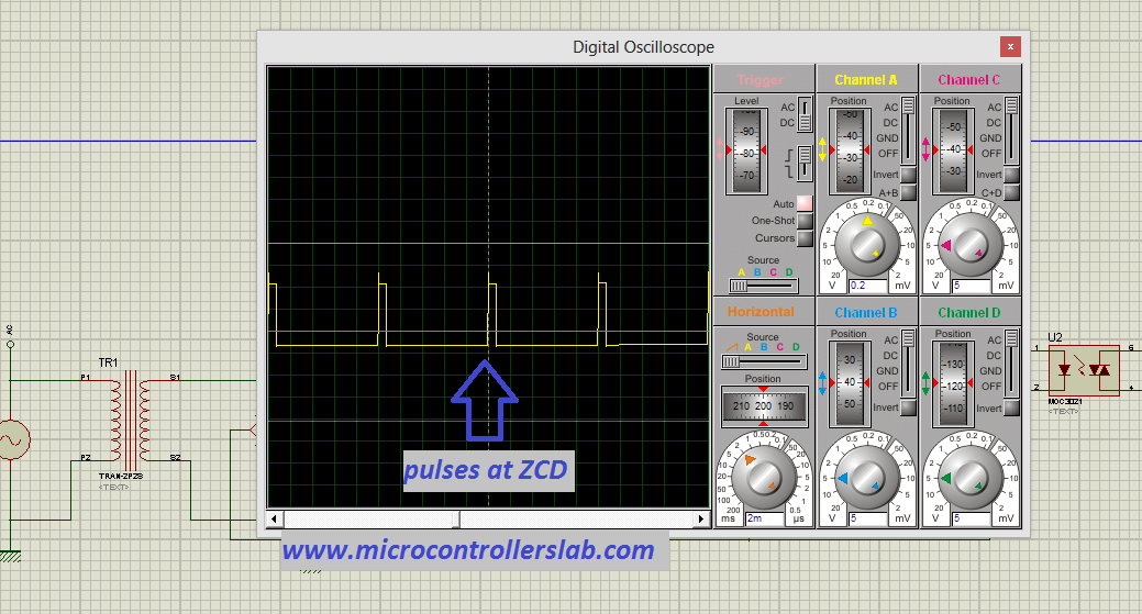
The inverting input of the comparator is connected to the output of the rectifier bridge, while a diode is connected to the non-inverting input. Whenever the voltage at the non-inverting input exceeds the inverting output voltage, the comparator output goes high, generating a pulse that indicates the detection of a zero crossing. The comparator output waveform can be observed below:
You may also like to read this:
- Zero Crossing Detection Circuits Examples
- MOC3041 Zero Crossing Optocoupler Pinout and Examples
- zero crossing detector circuit using pic microcontroller
Ramp Generator
Output of comparator is connected with a transistor and a capacitor. The capacitor charges through a 12-volt source. The transistor turns on only when a zero crossing occurs. This is because the comparator produces a pulse at the zero crossing, which turns on the transistor. When the transistor is on, the voltage across the capacitor immediately becomes zero, creating a ramp. When the transistor is off, the capacitor continues to charge. This process is illustrated in the figure below:

The ramp voltage is compared to the output voltage from a variable resistor. If the ramp voltage is greater than the variable resistor output voltage, more power will be delivered to the load. This variable resistor is used to control the firing angle of the triac. An optocoupler, such as the MOC3021, is used to provide isolation between the high voltage side and the low voltage control signals side. The complete circuit diagram for the firing angle control circuit for the triac is shown below:
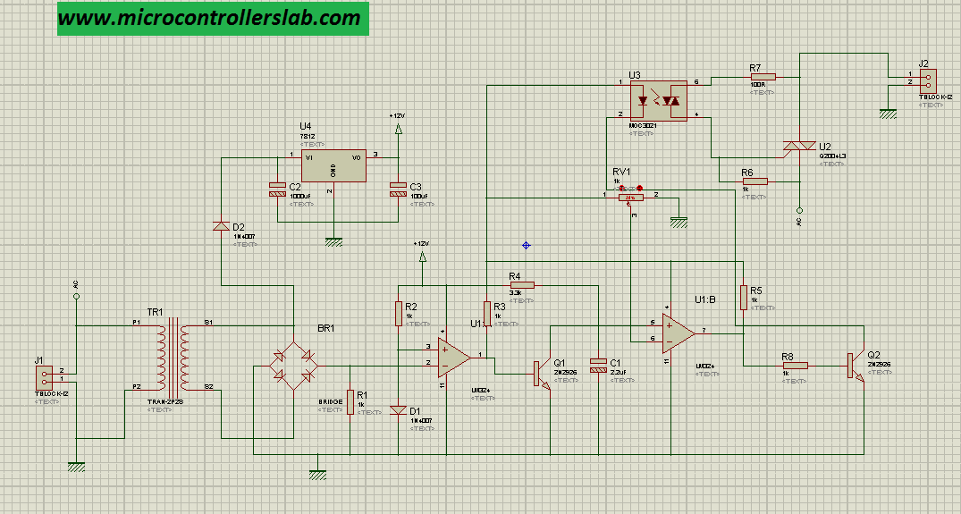
Diagram below shows output of voltage appearing across lamp. I have used lamp in Proteus for simulation purpose. Simulation results of firing angle control circuit for triac is shown below :

When output of second compartor is on, triac is also on and voltage is also appearing across load. When output of second comparator is off triac is also off and zero voltage is appearing across load. Variable resistor can be used to adjust turn on or off time and in return voltage magnitude across load.
Demonstration
To understand working of firing angle control circuit for triac watch following video :
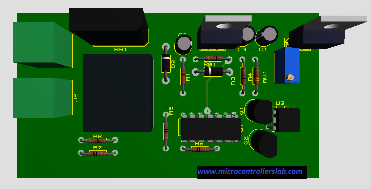
Top view :
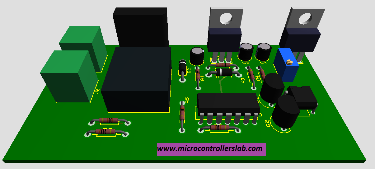
Front view :
Conclusion
In conclusion, this post has provided a comprehensive overview of the Triac Firing Angle Control Circuit. We have discussed its functionality, components, applications, and potential drawbacks.
The Triac Firing Angle Control Circuit is a valuable tool in electronic systems where precise control of power delivery to loads is required. With its ability to adjust the firing angle of a triac, this circuit enables control over the amount of power flowing to the load, allowing for applications such as lighting control, motor speed control, and temperature regulation.
Recommended readings:
- adjustable firing angle control of thyristor using arduino
- AC load interfacing with pic microcontroller
- MOC3021 Triac drive Optoisolator pinout, working, examples
- SFH620A Optocoupler
- MOC3041 Zero Crossing Optocoupler Pinout and Examples
- Soft starter for 3 phase induction motor using Arduino
- AC Dimmer of Two Loads Using Single Controller
- Programmable AC Power Control Using Pic Microcontroller
- soft starter for single phase induction motor using pic microcontroller
Dear Mr. Bilal Malek;
Would you please specify more details about ICs used (their codes or names), and other components (like to what value the transformer should step the voltage down, resistors, capacitors…etc) since I am going to build this circuit and I can’t see specifications clearly.
I would be very granted.
Regards
watch video for components description
GOOD WORK
SATISFATORY
Hello, came across your site and it is what i have been looking for a while. I have a project on phase control of heating sytems. i am confused if i should use the microcontroller you used in your post for AC Power control or the one you used for your post on Triac Firing angle. Thank you for your earnest reply.
Hi, I can’t see the video. It has error 504. Will you send it to my email or upload it somewhere else?
Can this be used with an Arduino Uno ?
yes you can
So how are the pins set on an arduino uno ? And can the triac be set to fire at the peak? What is the software you have used for the oscilloscope and schematics ?
Assalaam alaykum Bilaal..can I have a full circuit diagram of that project please
a 100ohms load is connected to peak supply of 300V through a control half wave rectifier the load power is to varied from 25watt to 80watt. what is the angler firing control required? Neglect forward drop of the control please I need answers or formula to calculate it
Where the programming code for this project?
no need of program for this project
hello sir actually when i simulated this circuit on proteus first I used 50Hz alternator on the output it showed the firing angle of only one half of wave but when I set frequency of 25Hz it showed the required output kindly tell is it designed for 25Hz and how can I control the firing angle with 50Hz as well???
hello
i need to make a project on lamp following different intensity without switch for different firing angle
for 25%(first1 sec increasing than constant for 1 sec then decreasing or 1 sec )
for 50%(first 2sec increasing than constant for 2 sec then decreasing or 2 sec )higher intensity
for 75%first 3sec increasing than constant for 3 sec then decreasing or 3 sec )higher intensity than above
using micro controller
What optoisolator can be used for 415v ac operation?