Zero crossing detector circuit is designed to detect the zero crossing of a sine wave. It is used for AC Power control circuits. If you are an electronics engineer and you are working on power electronics projects, you may come across many situations where you have to read the frequency of a sine wave or you want to detect the zero crossing of a sine wave. Whenever a sine wave crosses from the positive cycle to the negative cycle or from the negative cycle to the positive cycle, you can also detect the zero crossing of a sine wave with the help of a simple operational amplifier. I have already posted an article on zero crossing detection using op-amp.
But in this article, I am going to discuss how to detect zero crossing using the PIC16F877A microcontroller and some other simple electronic components. There are many projects on zero crossing detection available on many websites. However, none of them provides complete information about the zero crossing detector circuit. In many power electronics projects, you want to use zero crossing detection and also a microcontroller. For example, the zero crossing detector circuit is used in sine wave frequency measurement. In a digital frequency meter, you want to display the frequency value on a liquid crystal display. So you must need a microcontroller that can measure the time between two consecutive zero crossing detections. This measured time can be used to measure the frequency of the sine wave after some manipulation in the program.
What is Zero Crossing Detection?
Zero crossing detection refers to the identification of points in an electrical waveform where the voltage or current signal crosses the zero-volt reference level. In an AC (alternating current) waveform, the voltage and current oscillate between positive and negative values, crossing zero volts or zero current at regular intervals. The zero crossing points occur twice during each cycle of the AC waveform (once during the positive half-cycle and once during the negative half-cycle).
Zero Crossing Detector Circuit Components
The following main components are used in this electrical project. Brief descriptions of these components are also given below:
Voltage source
220volt or 120 volt sine wave voltage source which you want to detect zero crossing using zero crossing detector circuit using pic microcontroller.
Voltage limiting resistors
Two voltage limiting resistors are used to limit the voltage. The maximum voltage drops across these resistors. AC voltage less than 5 volts appears across the full bridge rectifier. Now the question is, why do we need voltage limiting resistors in this circuit? Because microcontrollers cannot read voltage more than 5 volts, or voltage more than 5 volts can permanently damage the microcontroller. Two 220K resistors are used as voltage limiting resistors in this project. You can use quarter-watt resistors because the current flow is in the order of microamperes through voltage limiting resistors.
Bridge rectifier
After voltage-limiting resistors, a full bridge rectifier circuit is used. It is used to convert the negative cycle into a positive half cycle or to convert AC voltage into pulsating DC voltage. This is because, after the full bridge, an NPN transistor is used as a switch that only turns off on zero crossing.
NPN transistor
The NPN transistor is used in this project as a switch, which provides a positive edge interrupt to the microcontroller during zero crossing. You can use any NPN transistor. I have used the 2N3904 NPN transistor in this project.
PIC16F877A microcontroller
The specific relevant content for this request, if necessary, delimited with characters:PIC16F877A microcontroller is the main part of this project because it measures zero crossing with an external interrupt. Whenever the sine wave crosses zero point, a positive edge interrupt is produced at the output of the NPN transistor. The microcontroller measures this interrupt and generates a small pulse at PORT D pin number zero or PD0.“`
Circuit diagram of zero crossing detector circuit using PIC microcontroller
A circuit diagram of a zero-crossing detector is given. I have tried to explain all the components of the zero-crossing detector circuit above. But if you still have any confusion, your comments are welcome.
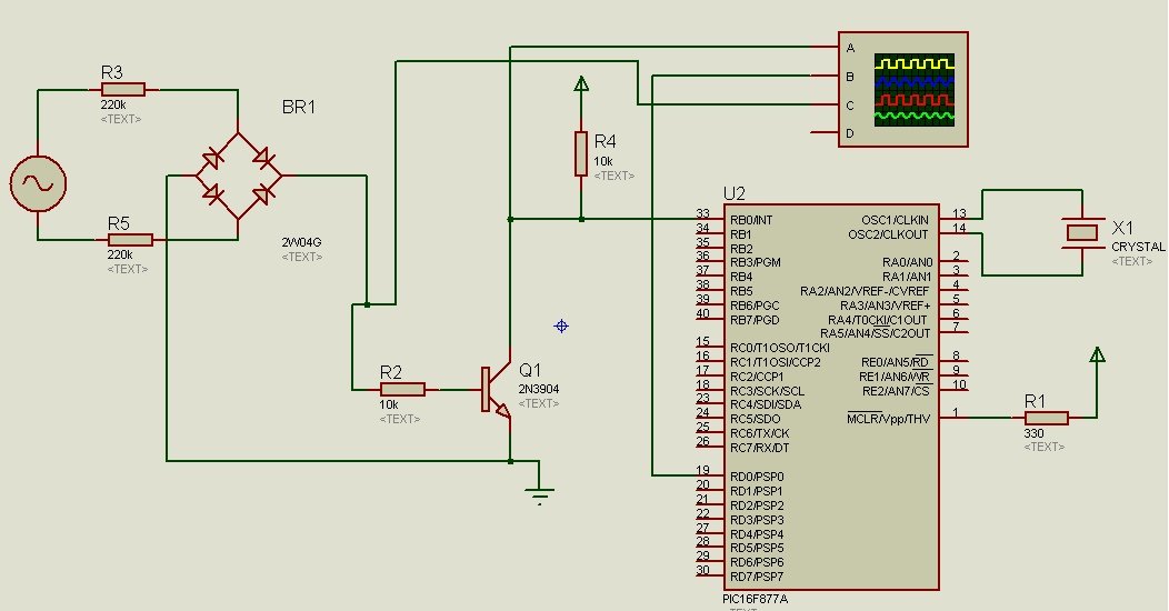
Microcontroller PIC16F877A uses an external interrupt to read the zero crossing point of a sine wave. If you are unfamiliar with programming PIC microcontrollers and would like to learn about them, please refer to the following articles:
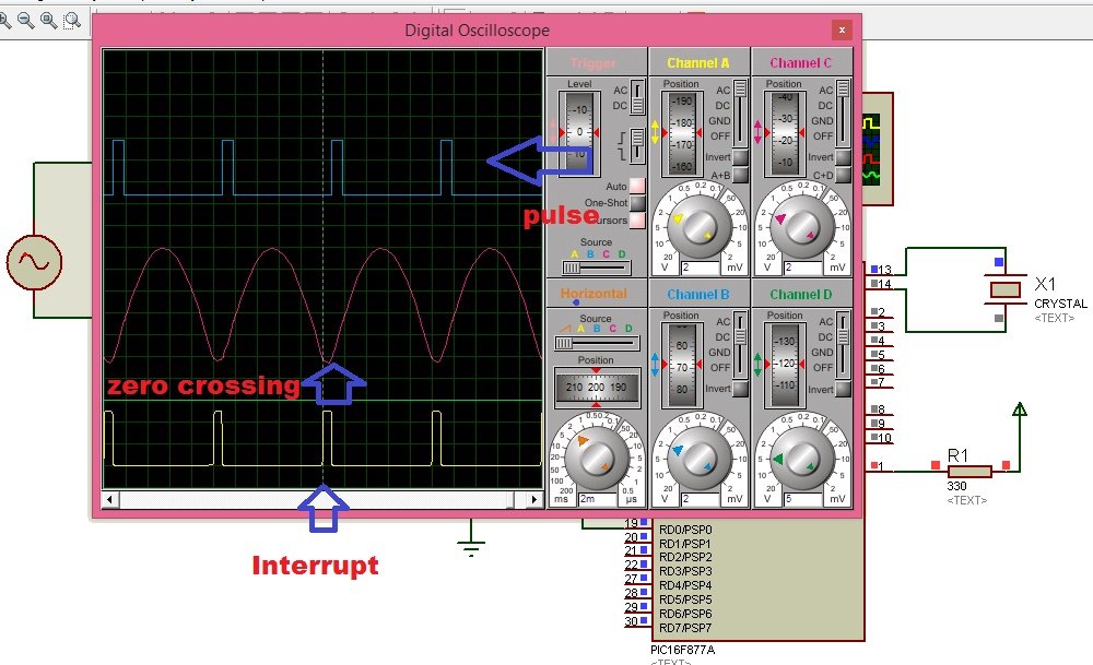
Simulation
Simulation results of the zero-crossing detector circuit are shown in the figure below. Labels are also shown for zero-crossing, pulse, and interrupt.
List of components
Category,Reference,Value,Order Code
Resistors,"R1",330,
Resistors,"R2",10k,
Resistors,"R4",10k,
Integrated Circuits,"U2",PIC16F877A,
Transistors,"Q1",2N3904,
Miscellaneous,"BR1",2W04G,
Miscellaneous,"X1",CRYSTAL,
Code
The code for this project is written in the MIKROC compiler and 8Mhz crystal is used in this project. If you do not know how to use MikroC for Pic, you can refer to these tutorials:
- How to Use “MikroC PRO for PIC” to Program PIC Microcontrollers
- Pic microcontroller programming in c using Mikroc Pro for PIC
The following code is an implementation of zero crossing detection using a PIC16F877A microcontroller written in the MikroC programming language. The program utilizes an external interrupt triggered by a falling edge on the RB0 pin, which is connected to a zero-crossing detection circuit. The zero crossing event is signaled by setting a flag (ZC) in the interrupt service routine (ISR). This flag is then checked in the main loop to detect when a zero crossing occurs. When the zero crossing is detected, the code toggles the state of an LED connected to the RD0 pin, generating a 1ms pulse. The delay_ms(1) function ensures that the pulse remains active for 1 millisecond.
// Components:
// 1. Microcontroller with external interrupt capability
// 2. LED connected to PORTD, Pin 0 (RD0)
// 3. Zero crossing detection using external interrupt on RB0

// Define flag for zero crossing detection
unsigned char FlagReg;
sbit ZC at FlagReg.B0;

// Interrupt Service Routine for external interrupt
void interrupt()
{
    if (INTCON.INTF)
    {
        // INTF flag raised, indicating an external interrupt (zero crossing)
        ZC = 1;              // Set zero crossing flag
        INTCON.INTF = 0;     // Clear the interrupt flag
    }
}

void main()
{
    // Initialize PORTB, PORTD, and configure pins
    PORTB = 0;
    TRISB = 0x01;  // RB0 is configured as input for external interrupt
    PORTD = 0;
    TRISD = 0;     // PORTD configured as output for LED

    // Configure external interrupt settings
    OPTION_REG.INTEDG = 0;   // Interrupt on falling edge
    INTCON.INTF = 0;         // Clear the interrupt flag
    INTCON.INTE = 1;         // Enable external interrupt
    INTCON.GIE = 1;          // Enable global interrupt

    // Main loop
    while (1)
    {
        if (ZC)
        {
            // Zero crossing occurred
            PORTD.F0 = 1;   // Send a 1ms pulse by turning on the LED
            delay_ms(1);
            PORTD.F0 = 0;   // Turn off the LED
            ZC = 0;         // Reset zero crossing flag
        }
    }
}
How Does Code Work?
Here is a line-by-line explanation of the code:
These lines declare an unsigned char variable called FlagReg which will store the flag for zero crossing detection. The sbit keyword is used to define a single bit variable named ZC at the bit position B0 of FlagReg.
unsigned char FlagReg;
sbit ZC at FlagReg.B0;
This is the interrupt service routine (ISR) for the external interrupt. Whenever there is an external interrupt triggered, this ISR will be executed. It checks if the interrupt flag INTF in the INTCON register is raised, indicating an external interrupt (zero crossing). If the flag is raised, it sets the ZC flag to 1 and clears the interrupt flag.
void interrupt()
{
    if (INTCON.INTF)
    {
        ZC = 1;
        INTCON.INTF = 0;
    }
}
These lines initialize the PORTB, PORTD registers by setting them to 0 (no voltage) and configure the corresponding pins as inputs and outputs. PORTB is configured as an input for the external interrupt, and PORTD is configured as an output for the LED.
void main()
{
    PORTB = 0;
    TRISB = 0x01;
    PORTD = 0;
    TRISD = 0;
These lines configure the external interrupt settings. OPTION_REG.INTEDG is set to 0, which means the interrupt will be triggered on a falling edge. INTCON.INTF is cleared to ensure there are no pending interrupts. INTCON.INTE is set to enable the external interrupt. INTCON.GIE is set to enable global interrupts.
OPTION_REG.INTEDG = 0;
INTCON.INTF = 0;
INTCON.INTE = 1;
INTCON.GIE = 1;
This is the main loop of the program. It continuously checks the value of the ZC flag. If the flag is set (indicating a zero crossing), it sets the RD0 pin (connected to an LED) to 1 to generate a 1ms pulse. Then it waits for 1 millisecond using the delay_ms function. After that, it sets the RD0 pin back to 0 to turn off the LED. Finally, it resets the ZC flag to 0.
while (1)
{
    if (ZC)
    {
        PORTD.F0 = 1;
        delay_ms(1);
        PORTD.F0 = 0;
        ZC = 0;
    }
}
The code essentially waits for a zero crossing event, and when detected, it generates a 1ms pulse on an LED using the PIC microcontroller.
Zero Crossing Detection Applications
Zero crossing detection is particularly useful in various applications, and it serves several purposes:
Synchronization: In power systems, zero crossing detection is crucial for synchronizing the operation of devices or systems with the AC waveform. For example, it is often used in phase-locked loops (PLLs) to synchronize the frequency and phase of an oscillator with an incoming AC signal.
Switching Control: In electronic circuits and power electronics, zero crossing detection is used to determine the optimal timing for switching operations. For example, in phase-locked loops used in motor control, zero crossing detection helps in synchronizing the switching of power devices (such as transistors) with the zero crossing points to reduce switching losses and improve overall efficiency.
Dimmer Control: In lighting systems, especially in dimmer circuits for incandescent or dimmable LED bulbs, zero crossing detection is employed to control the timing of the phase-cut dimming. This helps in minimizing the generation of electrical noise and reduces stress on the lamp.
Audio Signal Processing: In audio applications, zero crossing detection can be used for various purposes, such as pitch detection, audio compression, and waveform analysis.
Zero crossing detection is typically implemented using specialized circuits or algorithms in digital signal processing. It involves monitoring the waveform and detecting the point at which the signal crosses the zero level. This information is then utilized for synchronization or control purposes in various electronic systems and applications.
You may also like to read:
this post is very useful for me.i expect more from you . thank you 🙂
you are welcome. Keep visiting our blog for more useful information
What is the difference between a ZCD realised using an Op-amp and a ZCD realised using a microcontroller? If we can create a microcontroller based ZCD why are Op-amp ones still in use?
Using microcontroller you can use it for many other function which requires for power electronics circuits like firing angle control circuit. But you can also use op amp for same function. Microcontroller reduces required circuitry for designing any circuit
thank you for sharing this project , please tell me how can i measure and display phase angle between 2 sinusoïdes
use timers between consecutive zero crossings
hi thank you but what component you use on the other side of the resistor and also i try to run it on multism the scem diagram but it doesnt run what did ya think the problem i made please tell me this two things
Hi
Thanks for your information.. Can you please tell me whether this zero crossing circuit can be applied to STM8S Discovery micro controller also, If no can you please suggest for this zero crossing with STM8S Discovery micro controller…
yes it can be applied to stm8.Same principle
Helpful discussion – I loved the specifics – Does someone know where I might be able to acquire a blank a form copy to edit ?
Dear sir,
Might be i am so young.
I see a project that is a circuit for control temperature and it also use zero cross. But i do not know why we use zero cross and what the zero cross processing in it. Could you explain me, please?
Sir,i want code for zct in MPLab compiler plz .
How to measure time at the output of Zero cross detector to find out frequency of voltage signal because f=1/2T so if we find out the time between zero crossing we can calculate frequency
What is if on the output of the Bridge Reticifier is a offset and the NPN doesnt switch anymore?
Hi,
I need a professional help in designing a mains driven, dc motor drive using 2 thyristors…
contact me at microcontrollerslabhub@gmail.com if you want to avail paid services
Why npn transistor is giving pulses on zero crossing here? Shouldn’t it be always on because there is always positive voltage across base-emitter junction? Please explain.
wow this is wonderfull, i really benefit frm this,
can you please answer this questions
* how do we now if the crossing is from negative to positive or opposite, and from my multimeter the emitter -collector voltage which is what i consider as the interrupt value is always giving me 4.04mV when i sent in 220Vac
I got previous one but, how will we determine whether the zero crossing is negative to positive transition of positive to negative transition of voltage?
Hi
Would you please give me any idea about measuring the sinewave amplitude using this zerocrossing metod .Thanks in advance
Sir help me
write an arm microcontroler program to find zero crossing in sine wave and display number of zero crossing upon occurance of an interrupt
can you modify if for three phase load control
I am using stm32f4 series , how we can detect the zero crossings of multilevel inverter using only the microcontroller without any kind of additional circuit using keil vision for programming.
Hi
Which type of signal you are using? AC high volt?
220 volts ac supply .. actually I have to parallel the five level inverters.. for which I need zero crossing detection
You have to use external components. You can give high voltage to a microcontroller directly. Use a step down transformer to convert 220-12 volts. Then use a voltage divider to further step down to less than 5 volts. After that convert negative cycle into postivie cycle using a bridge rectifier or op-amp ( by increasing dc level of AC) Then you can use this circuit.
Can we do that by programming on keil ?? Like I am usnig stm32f407
Yes you can do that
How to differentiate between positive to negative and negative to positive because it will be very important a my three phase firing circuit
It is very useful information blog. Thank you for your sharing.
How we can find out zero crossing detector using comparator
Hello Folks,
I want to make program for ZCD using Atmega16, my aim is to make dimmable light without using PWM, Can anyone help me? What should I do? I have written sample program of ON and OFF which I have shown below.
//#ifndef F_CPU
#define F_CPU 16000000UL
//#endif
#include
#include
#include
void init_ports()
{
DDRB=0x08; /* Make PORTB as output PORT*/
PORTB=0x08; /* Write the value on PORTB*/
}
void init_interrupts()
{
cli(); //Disable global interrupt
GICR=(1<<INT2); //Set interrupt2(INT2)
MCUCSR=(1<<ISC2); //Set MCU Control and Status Register on Rising Edge
sei(); //Enable global interrupt
}
ISR(INT2_vect)
{
PORTB=1<<PORTB3; //HIGH
_delay_ms(50);
PORTB=0<<PORTB3; //LOW
_delay_ms(50);
}
int main(void)
{
init_ports();
while(1)
{
init_interrupts();
}
return 0;
}
sir , I have made a zero crossing circuit using your instructions. My simulation is working correctly but my hardware part is didn’t work. I have connected all the things according to your diagram. sir please help me