In this tutorial, you will learn how to interface AC load with pic microcontroller or any other microcontroller. Why we need a optocoupler to interface AC load with microcontroller? Why we can not connect AC load directly with microcontroller? What are the applications of AC load interfacing with pic microcontroller? AC load interfacing with pic microcontroller has many applications in power electronics projects. Do you ever think about controlling AC power flow to a load by controlling the ac voltage ? There are many other application of AC load interfacing with PIC microcontrollers. Some of the project which used this concept are given below:
Can we connect AC load directly with microcontroller( AC load interfacing) ?
Big No. We can not connect AC load directly with microcontroller. Microcontrollers are digital electronics devices and their operating voltages are between 3.3V to 5V DC. Microcontrollers have limited input and output current capability. Because we need to drive switching devices like triac, thyristor and transistors. Microcontrollers can not provide sufficient current to drive these switching devices. Other reason we can not connect microcontroller direclty with AC load is due to protection issues. Switching devices generally produce back EMF and the value of Back EMF depend on the applications. But this Back EMF is dangerous for digital devices like microcontrollers and it may get damaged. So we need to make sure back EMF can not reach to microcontroller directly. So we often use Optocoupler. So now lets see what is a Optocoupler? I recommend you to read following topic:
What is Optocoupler?
Optocoupler is basically used for isolation/protection in power electronics devices. It is used to isolate high voltage side from low voltage side. As I mentioned earlier, it is also used to avoid back emf effect to microcontrollers. Back EMF effect occurs only in inductive devices like motors etc. There are many types of Optocoupler available in market. Let us see how we interface the microcontroller to a AC load. To interface AC load with microcontroller, we need a optcoupler. We have an Optocoupler MOC3041. You can also use following optocouplers.
- MOC3042
- MOC3046
- MOC3043
MOC3041 Optocoupler have zero voltage crossing detector inside it. Pinout of MOC3041 Optocoupler is shown below: 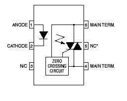 Pinout of MOC3041 optocoupler is shown above. Input side has a light emitting diode. Pin number 1 is anode of LED and Pin number 2 is cathode of LED. When LED is on, it emits light and light falls on light sensitive triac. Triac turns on when light falls on it. Because MOC3041 has built in zero crossing detector circuit inside it, triac will turn on at every zero crossing of AC power supply only. Zero crossing switching has many advantages in power electronics circuits which I can not discuss here and it is beyond the scope of this article. I will try to write a separate article on it. So to connect ac load with microcontroller, we connect MOC3041 optocoupler between ac load and pic microcontroller as a isolation. Complete interfacing diagram is shown below.
How to interface AC load with any microcontroller
Circuit diagram for AC load interfacing is shown below. In this circuit diagram of AC load interfacing, we are using opto isoloator, triac , indication LED, resistors and AC lamp.

So in the event of using this IC with micro controller we have connected one LED and current limiting resistor in series to understand that what will happened when current goes high and current goes low. Led is also used to show the indication of working of circuit. This may or may not be used but this gives a good indication that the current is flowing through the internal LED. we are not able to see the light of internal LED of optocoupler which will be ultimately falling on photo sensitive triac. When light falls on photo sensitive triac, triac will start conducting. We can turn on and turn off the internal LED of optocoupler with the help of digital output pin of pic microcontroller. If you don’t know how to use input output ports of pic microcontroller, I recommend you to read this article:
As shown in above diagram when we give high signal to input of optocoupler MOC3041 from microcontroller output pin, internal light emitting diode will start glowing and light of LED will fall on photo sensitive triac and triac will turn on. When triac start conducting, current will flow from ac supply to ac lamp. This is how we can interface ac load with microcontroller through optocoupler and triac.
Circuit diagram of AC LOAD interfacing with pic microcontroller
Circuit diagram for AC load interfacing with pic microcontroller is shown below. PIC16F877A microcontroller is used to control the AC load. 
Push button is connect with pin number 7 of PORTD of pic16f877A microcontroller. When we push the button, output at pin number 4 of PORTB becomes high and AC load turn on and when we release or push the button again, ac load turn off. So this how easy it is to interface ac load with pic microcontroller.