GPS based speedometer using pic microcontroller: This project is about how to design speedometer using pic microcontroller without using any speed measurement sensor. In this GPS based speedometer project, I have used GPS module to measure the speed of any person, car, a vehicle with the help of GPS module. GPS module receives data from satellites and this received data can also provide us our speed relative to our position on earth. It used out latitude and longitude relative position to calculate our speed.
In this pic microcontroller based project, I have used Holux GPS module and PIC16F877A microcontroller and an LCD to display speed in kilometer per hour. It can also provide us speed in knots. If you want to make this project you should know how to interface LCD with pic microcontroller and how to interface Holux GPS module with pic microcontroller. Before starting on GPS based speedometer, let me give you some brief introduction on how to interface GPS module with pic microcontroller.
 In my last tutorial on GPS module interfacing, I have described how to receive data from GPS module. I will provide a little bit more information about it here. If you want to read more about it, I recommend you to go that article a read it first. So let’s start with little bit introduction, when we powered up GPS module by providing it the power of 5 volts, it will automatically connect with satellites and starts receiving data from them. GPS module will automatically send its data on transmit pin of GPS module. We can receive this data from transmitting pin with the help of serial communication using UART communication of pic microcontroller. So you should know how to use serial communication with pic microcontroller to send and receive data serially. I recommend you to check this post on
We can receive this data from transmitting pin with the help of serial communication using UART communication of pic microcontroller. So you should know how to use serial communication with pic microcontroller to send and receive data serially. I recommend you to check this post on serial communication using pic microcontroller before going further in this article. Some GPS modules work on I2C communication but I recommend you to use those modules which work on serial communication because it is easier to use.
working of GPS based speedometer using a pic microcontroller
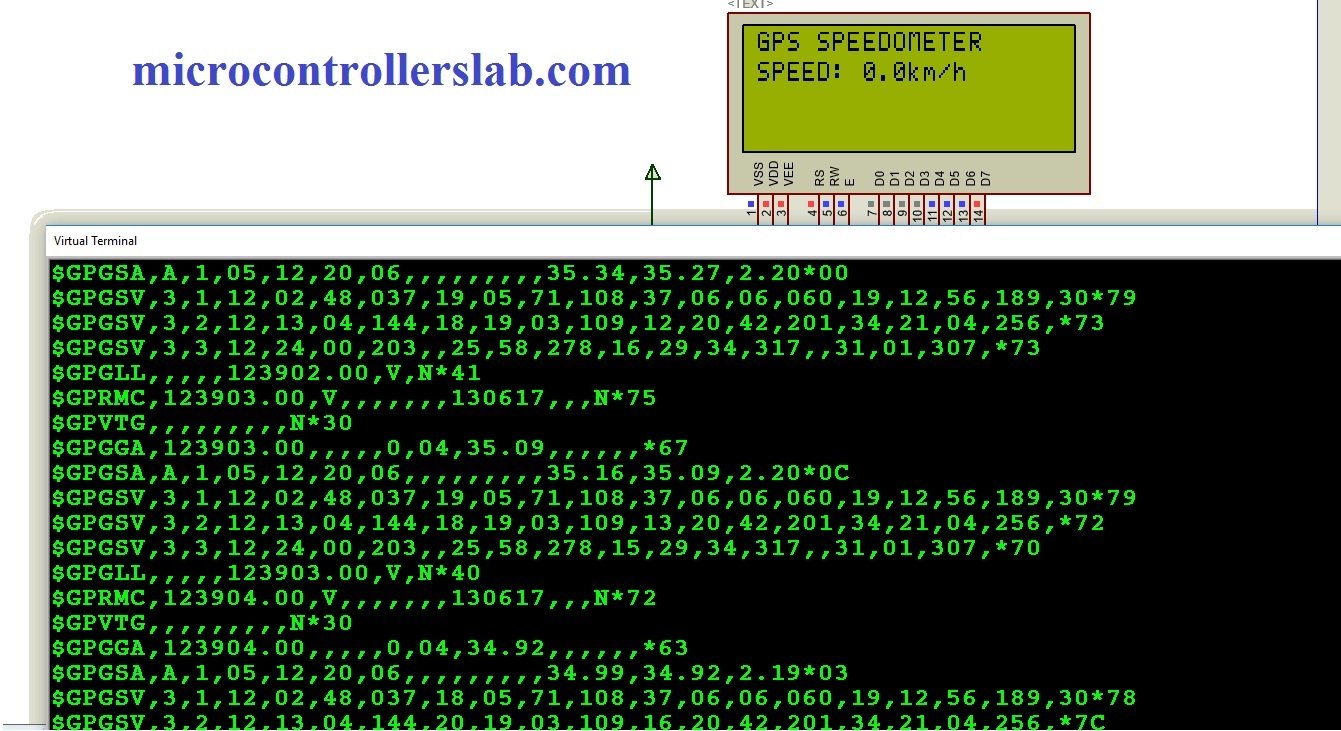
So now I am going to explain a working of GPS based speedometer using pic microcontroller. Here I will explain how pic microcontroller receives data from GPS module and how we extract only speed from that data. I have also posted a project on a GPS-based clock and GPS-based coordinates on LCD. In those two projects, I have extracted time and coordinates data from the data received from GPS receiver. But in this GPS based speedometer project, we will extract speed from the $GPVTG string as shown below: 
Above commands on GPS NMEA commands which we receive from GPS receiver. We can use any string or any command according to our requirement. But in this project we are using $GPVTG, becuase it is used to track ground speed. Every command provides a unique information. you can check this link for more information on NMEA commands. As shown in above picture, we will use $GPVTG string to extract speed in kilometer per hour. Details of this string are given below: 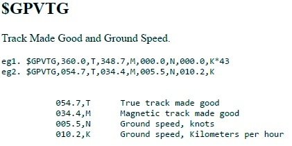
so in $GPVTG string 010.2,k is ground speed in kilometers per hour. So we need to get this data only from this string to measure speed in kilometer per hour or to design GPS based speedometer using pic microcontroller. So you should write an algorithm to receive data from GPS receiver and extract only speed from received data.
Circuit diagram of GPS based speedometer
Circuit diagram of GPS based speedometer is given below. transmit pin o GPS receiver is connected with receive pin of pic16f877a microcontroller and the 5-volt power supply is connected to GPS module. LCD is connected with PORTB of pic16f877a. you can connect it to any port you want. But you need to make changes in code accordingly.
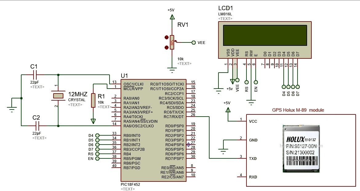
12 MHz external crystal is used. Here resistor R1 is connected with a master clear pin of microcontroller and 5 volts which are a reset pin. So this is a simple circuit diagram of this embedded systems based project. But the main thing in this GPS based speedometer project is a code.
Code
// LCD module connections
sbit LCD_RS at RB4_bit;
sbit LCD_EN at RB5_bit;
sbit LCD_D4 at RB0_bit;
sbit LCD_D5 at RB1_bit;
sbit LCD_D6 at RB2_bit;
sbit LCD_D7 at RB3_bit;

sbit LCD_RS_Direction at TRISB4_bit;
sbit LCD_EN_Direction at TRISB5_bit;
sbit LCD_D4_Direction at TRISB0_bit;
sbit LCD_D5_Direction at TRISB1_bit;
sbit LCD_D6_Direction at TRISB2_bit;
sbit LCD_D7_Direction at TRISB3_bit;
// End LCD module connections
char gps[7];
void GPS_GetDataAndDisplayIt(void)
{
char Temp = 0, Index = 0, i=0;
while(!UART1_Data_Ready());
Temp = UART1_Read();
if (Temp == '$')
{
while(!UART1_Data_Ready());
Temp = UART1_Read();
if (Temp == 'G')
{ while(!UART1_Data_Ready());
Temp = UART1_Read();
if (Temp == 'P')
{
while(!UART1_Data_Ready());
Temp = UART1_Read();
if (Temp == 'V')
{
while(!UART1_Data_Ready());
Temp = UART1_Read();
if (Temp == 'T')
{
while(!UART1_Data_Ready());
Temp = UART1_Read();
if (Temp == 'G')
{
while(i<7)
{
while(!UART1_Data_Ready());
Temp = UART1_Read();
while (Temp != ',' )
{
while(!UART1_Data_Ready());
Temp = UART1_Read();
}
i++;
}
Lcd_Cmd (_LCD_SECOND_ROW);
Lcd_Out_Cp("SPEED: "); // displaying Latitude data
while(!UART1_Data_Ready());
Temp = UART1_Read();
i=0;
while(!UART1_Data_Ready());
Temp = UART1_Read();
while (Temp != ',')
{
Lcd_Chr_Cp(Temp); // Displaying latitude on LCD
while(!UART1_Data_Ready());
Temp = UART1_Read();
i++;
}
while(i<7)
{
while(!UART1_Data_Ready());
Temp = UART1_Read();
i++;
}

//Lcd_Out_Cp(gps);
Lcd_Out_Cp("0.0km/h"); // displaying Latitude data
i=0;
}

}

}

}

}
}

}
void main()
{
Lcd_Init(); // Initialize LCD
UART1_Init(9600); // Initialize UART module at 9600 bps
Delay_ms(100); // Wait for UART module to stabilize
Lcd_Cmd(_LCD_CLEAR); // Clear display
Lcd_Cmd(_LCD_CURSOR_OFF); // Cursor off
Lcd_Cmd (_LCD_FIRST_ROW);
Lcd_Out_Cp("GPS MODUE");
Lcd_Cmd (_LCD_SECOND_ROW);
Lcd_Out_Cp("DATA LOGGER");
Lcd_Cmd (_LCD_THIRD_ROW);
Lcd_Out_Cp("SD CARD");
Lcd_Cmd (_LCD_FOURTH_ROW);
Lcd_Out_Cp("BY BILAL");
Delay_ms(2000);
Lcd_Cmd(_LCD_CLEAR); // Clear display
Lcd_Cmd (_LCD_FIRST_ROW);
Lcd_Out_Cp("GPS SPEEDOMETER");
while(1) {

GPS_GetDataAndDisplayIt();
// Lcd_Out(3,1,gps);
//delay_ms(500);
}

}
You can write its code if you know about serial communication and have knowledge of string parsing in c programming.