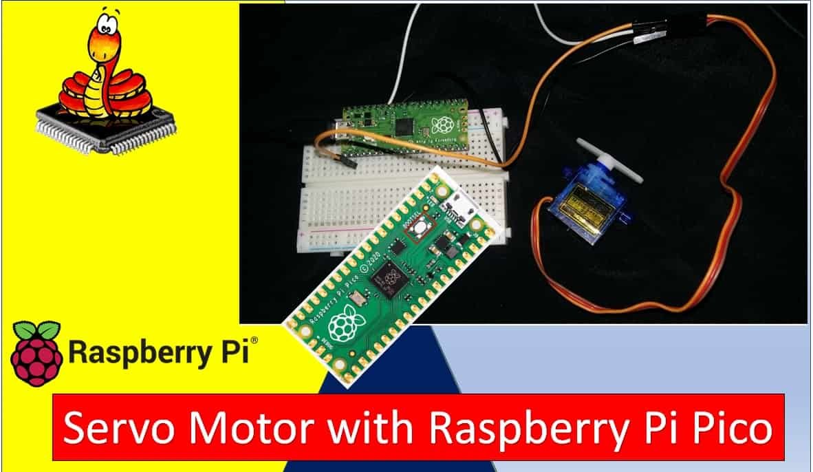
In this tutorial, we will learn how to interface and control the SG-90 servo motor with the Raspberry Pi Pico using MicroPython. We will start with an introduction to servo motors and PWM, then walk through the wiring, code, and a practical demonstration. By the end of this guide, you will be able to control servo motor positions precisely using MicroPython’s PWM library.
You may also like to read about DC motor and stepper motor interfacing with Raspberry Pi Pico:
- 28BYJ-48 Stepper Motor with Raspberry Pi Pico using MicroPython
- Control DC Motor using L298N Driver with Raspberry Pi Pico and MicroPython
Prerequisites
Before you begin, make sure you have completed the following steps:
- Downloaded and installed the latest version of Python 3 on your PC.
- Downloaded and installed the latest version of Thonny IDE.
- Set up MicroPython on your Raspberry Pi Pico.
If you need help with these steps, follow this guide:
If you are using uPyCraft IDE instead, check this guide:
What is a Servo Motor?
A servo motor is a rotary or linear actuator that allows for precise control of angular or linear position, velocity, and acceleration. Unlike a regular DC motor that spins continuously, a servo motor moves to a specific position and holds it. This makes servo motors ideal for applications such as robotics, RC vehicles, camera gimbals, automated door locks, solar panel tracking systems, and many other projects that require accurate and repeatable movement.
Servo motors contain a built-in control circuit, a DC motor, a gearbox, and a position feedback sensor (usually a potentiometer). The control circuit reads the PWM input signal and adjusts the motor position accordingly by continuously comparing the current position with the desired position and correcting any error.
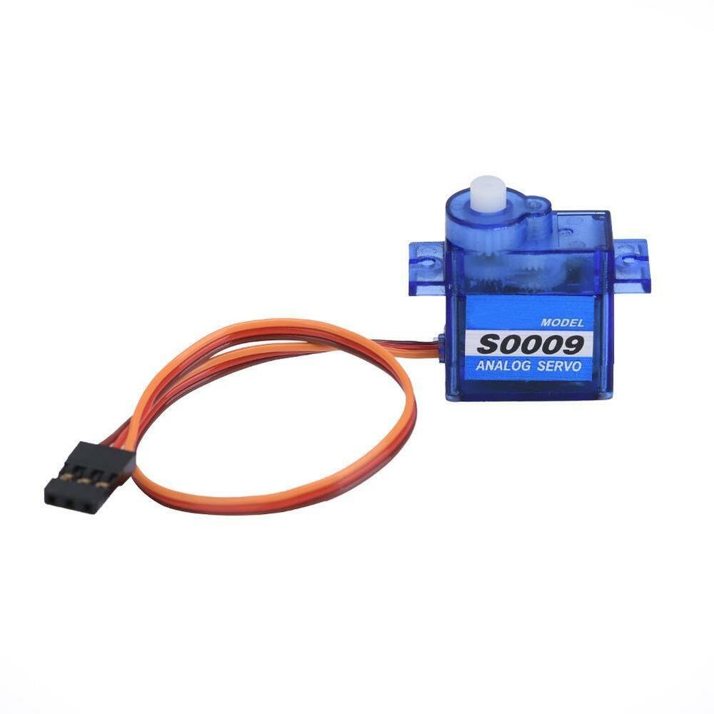
SG-90 Servo Motor
The SG90 is a lightweight, low-cost, and easy-to-use servo motor that is very popular in hobby and educational electronics projects. It can rotate up to 180 degrees and each movement step can be a maximum of 90 degrees. Its small form factor makes it ideal for robotic arms, camera panning mechanisms, and obstacle-avoidance robot projects. It only requires a single PWM signal to control its position.
The SG90 has the following key specifications:
- Operating Voltage: 4.8V to 6V (typically powered from 5V)
- Stall Torque: 1.8 kg/cm at 4.8V
- No-load Speed: 0.1 sec/60 degrees at 4.8V
- Weight: 9 grams
- Rotation Range: 0 to 180 degrees
- PWM Frequency: 50Hz (20ms period)
- Pulse Width Range: 1ms (0°) to 2ms (180°)
The following figure shows the pinout of the SG90 servo motor. It has three wires: PWM signal, GND, and VCC.
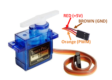
Pin Configuration Details
The VCC and GND pins are the power supply pins. The SG90 requires a 5V supply to operate. Most microcontroller development boards including the Raspberry Pi Pico provide a 5V output pin that can be used to power small servo motors.
| Wire Color | Pin Function |
|---|---|
| Red | Vcc (5V power supply) |
| Black or Brown | GND (Ground) |
| Yellow, Orange, or White | Control Signal / PWM input |
PWM Introduction
PWM (Pulse Width Modulation) is a technique used to generate an analog-like signal from a digital output pin. The signal alternates between HIGH and LOW at a fixed frequency, and the ratio of HIGH time to the total period is called the duty cycle. By varying the duty cycle, we can control the effective voltage or position of a connected device.
For servo motors, PWM is used to communicate the desired position to the motor’s internal control circuit. The servo reads the width of the HIGH pulse in each 20ms period and moves its shaft to the corresponding angular position.
What is Duty Cycle?
Duty cycle is the percentage of time during which the PWM signal remains HIGH within one complete period. For example, a 0% duty cycle means the signal is always LOW, and a 100% duty cycle means it is always HIGH. The formula is:
Duty Cycle = (ON time / Time Period) × 100%

PWM Frequency for Servo Motors
The standard PWM frequency for controlling servo motors is 50Hz, which corresponds to a period of 20 milliseconds. Within this 20ms period, the pulse width determines the servo shaft position. A 1ms pulse (5% duty cycle) moves the servo to 0 degrees, and a 2ms pulse (10% duty cycle) moves it to 180 degrees. Pulse widths between 1ms and 2ms produce positions between 0 and 180 degrees.
Frequency = 1 / Time Period
Time Period = ON time + OFF time
# For servo: Frequency = 50Hz, Period = 20ms
PWM Pins on Raspberry Pi Pico
The Raspberry Pi Pico contains 8 PWM slices, and each slice provides two independent PWM channels (A and B). This gives a total of 16 PWM outputs across all GPIO pins. Every GPIO pin can be configured as a PWM output, but pins that share the same PWM channel (e.g., GP0 and GP16 both use channel 0A) will output the same signal.

| GPIO | 0 | 1 | 2 | 3 | 4 | 5 | 6 | 7 | 8 | 9 | 10 | 11 | 12 | 13 | 14 | 15 | 16 | 17 | 18 | 19 | 20 | 21 | 22 | 23 | 24 | 25 | 26 | 27 | 28 | 29 |
| PWM Channel | 0A | 0B | 1A | 1B | 2A | 2B | 3A | 3B | 4A | 4B | 5A | 5B | 6A | 6B | 7A | 7B | 0A | 0B | 1A | 1B | 2A | 2B | 3A | 3B | 4A | 4B | 5A | 5B | 6A | 6B |
How to Control the SG-90 in MicroPython
To control the SG90 servo motor with the Raspberry Pi Pico in MicroPython, follow these steps:
- Choose a PWM-capable GPIO pin to connect the servo signal wire.
- Set the PWM frequency to 50Hz, which is the standard control frequency for servo motors.
- Use the
duty_u16()method to set the duty cycle. The Raspberry Pi Pico has a 16-bit PWM resolution in MicroPython, meaning values range from 0 to 65535. For the SG90, valid control values are approximately 1000 to 9000, corresponding to 0 to 180 degrees of rotation.
Understanding the Duty Cycle Values for SG-90
A reader in the comments section asked a great question: the SG-90 datasheet specifies that a 1500µs pulse corresponds to the 90-degree center position, with shorter pulses rotating clockwise and longer pulses rotating counter-clockwise. The values 1000 to 9000 used in this tutorial are raw 16-bit duty cycle counts, not microsecond pulse widths.
Here is how the mapping works: with a 50Hz frequency (20ms period) and a 16-bit counter (65535 max), a 1ms pulse corresponds to about 3277 counts and a 2ms pulse corresponds to about 6554 counts. The values 1000 to 9000 are empirically chosen for this particular MicroPython implementation and the SG90’s physical response range. The actual behavior may vary slightly between individual servo units, so fine-tuning may be needed for precise positioning.
For more accurate angle-based control, you can use the following formula to convert degrees to duty cycle counts:
# Formula to convert angle (0-180) to duty_u16 value
# Pulse range: ~0.5ms to ~2.5ms within a 20ms period
def angle_to_duty(angle):
    min_duty = 1638   # ~0.5ms pulse
    max_duty = 8192   # ~2.5ms pulse
    return int(min_duty + (max_duty - min_duty) * angle / 180)
Interfacing Raspberry Pi Pico and SG-90 Servo Motor
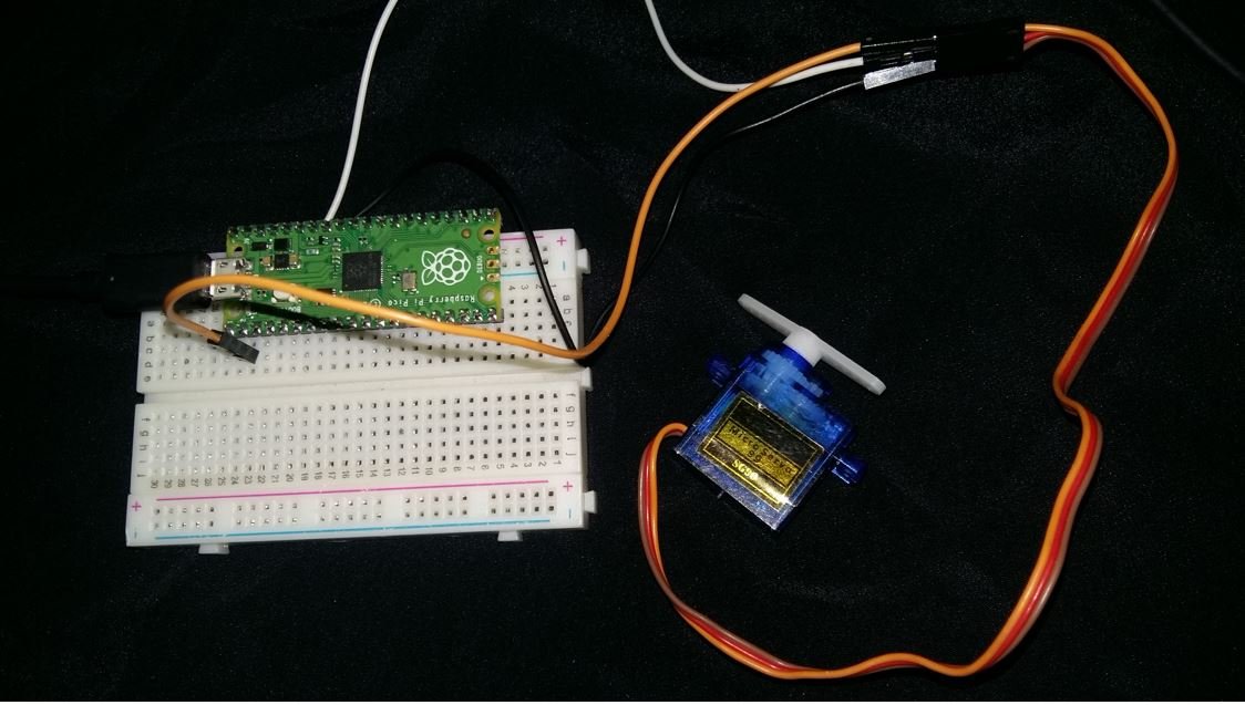
The following schematic diagram shows the wiring between the Raspberry Pi Pico and the SG90 servo motor.

The servo motor’s signal wire (orange or yellow) connects to GP1 on the Raspberry Pi Pico. You can use any suitable PWM-capable GPIO pin on your board. The VCC (red wire) connects to the Raspberry Pi Pico’s VBUS (5V) pin, and the GND (brown or black wire) connects to any GND pin on the board. If you are driving a servo that draws more current than the Pico can supply, use an external 5V power supply and share the common ground.
MicroPython Script: Control Servo Motor
The following MicroPython script moves the servo motor arm continuously from 0 to 180 degrees and back to 0 degrees.
from time import sleep
from machine import Pin, PWM

pwm = PWM(Pin(1))
pwm.freq(50)

while True:
    for position in range(1000, 9000, 50):
        pwm.duty_u16(position)
        sleep(0.01)
    for position in range(9000, 1000, -50):
        pwm.duty_u16(position)
        sleep(0.01)
How the Code Works
Importing PWM and Pin Classes
We import the PWM and Pin classes from MicroPython’s machine module. The sleep function from the time module is used to add delays between position steps.
from time import sleep
from machine import Pin, PWM
Create PWM Pin Object
We create a PWM object on GPIO pin 1 (GP1) by passing a Pin object to the PWM() constructor.
pwm = PWM(Pin(1))We then set the PWM frequency to 50Hz, which is required for standard servo motor control.
pwm.freq(50)Generate Variable Duty Cycle PWM
Inside the infinite loop, two for loops sweep the duty cycle value between 1000 and 9000. The range() function takes three parameters: start, stop, and step.
- First loop: Increments from 1000 (≈0°) to 9000 (≈180°) in steps of 50, moving the servo from 0 to 180 degrees.
- Second loop: Decrements from 9000 (≈180°) to 1000 (≈0°) in steps of -50, moving the servo back to 0 degrees.
- The
sleep(0.01)(10ms delay) controls the speed of rotation. A smaller delay makes the sweep faster; a larger delay makes it slower.
while True:
    for position in range(1000, 9000, 50):
        pwm.duty_u16(position)
        sleep(0.01)
    for position in range(9000, 1000, -50):
        pwm.duty_u16(position)
        sleep(0.01)
Moving the Servo to a Specific Angle
Instead of a continuous sweep, you may want to move the servo to a specific target angle. The code below demonstrates how to set the servo to any desired position between 0 and 180 degrees by converting the angle to the appropriate duty cycle value.
from time import sleep
from machine import Pin, PWM

pwm = PWM(Pin(1))
pwm.freq(50)

def set_angle(angle):
    # Map angle (0-180) to duty cycle (1000-9000)
    duty = int(1000 + (angle / 180) * 8000)
    pwm.duty_u16(duty)

# Move to 0 degrees
set_angle(0)
sleep(1)

# Move to 90 degrees (center)
set_angle(90)
sleep(1)

# Move to 180 degrees
set_angle(180)
sleep(1)
In this example, the set_angle() function converts a degree value to the corresponding 16-bit duty cycle count by linear interpolation between the minimum (1000) and maximum (9000) values. This makes it easy to control the servo to any desired position without manually calculating duty cycle values.
Practical Applications of Servo Motors with Raspberry Pi Pico
Servo motors are used in a wide range of real-world applications when paired with the Raspberry Pi Pico:
- Robotic Arm: Control multiple servo motors to create a multi-axis robotic arm that can pick and place objects.
- Pan-Tilt Camera Mount: Use two servo motors to create a two-axis camera gimbal that can track objects or be controlled remotely.
- Automatic Door Lock: Drive a servo motor connected to a door latch mechanism that can be triggered by a button, keypad, or Bluetooth command.
- RC Vehicles: Control the steering and throttle of model cars, boats, or aircraft using servo motors and the Pico’s PWM outputs.
- Solar Tracker: Use a light sensor and servo motor to keep a solar panel aligned with the sun throughout the day.
- Clock or Display Mechanism: Create analog gauges or clock hands driven by servo motor positions mapped to data values.
Troubleshooting Tips
If you encounter issues with the servo motor, here are common problems and solutions:
- Servo jitters or vibrates: This is often caused by an insufficient power supply. The Raspberry Pi Pico’s 5V VBUS pin may not supply enough current for the servo under load. Use a dedicated external 5V power supply and connect the grounds together.
- Servo moves only partially: The duty cycle range (1000–9000) may not match your specific servo’s calibration. Experiment with values between 500 and 10000 to find the full range for your motor.
- Servo does not respond: Verify the GPIO pin number and ensure the PWM frequency is set to 50Hz. Also confirm the signal wire is connected to the correct Pico GPIO pin.
- Servo makes a buzzing noise at the end of rotation: This happens when the duty cycle value slightly exceeds the servo’s physical limit. Reduce the maximum value slightly (e.g., from 9000 to 8500) to avoid mechanical stress.
- Servo moves erratically after power-up: Always initialize the servo to a known position (like 90 degrees) at the start of the program before issuing further commands.
Demonstration
Copy the code above into Thonny IDE and connect the servo motor to the Raspberry Pi Pico as shown in the connection diagram. Run the script and you will see the servo arm sweep continuously from 0 to 180 degrees and back, as shown in the video below.
You may also like to read other Raspberry Pi Pico tutorials:
- HC-05 Bluetooth Interfacing with Raspberry Pi Pico – Control Outputs
- Control DC Motor using L298N Driver with Raspberry Pi Pico and MicroPython
- DS18B20 Temperature Sensor with Raspberry Pi Pico using MicroPython
- DHT11 DHT22 with Raspberry Pi Pico using MicroPython
- HC-SR04 Ultrasonic Sensor with Raspberry Pi Pico using MicroPython
- I2C LCD Interfacing with Raspberry Pi Pico Display Text and Custom Characters
- BME280 with Raspberry Pi Pico using MicroPython
Related servo motor tutorials and projects:
- Interface MG995 Servo Motor with Arduino – Example Code
- CCPM Servo Consistency Master/Servo Motor Tester
- SG-90 Servo Motor Interfacing with TM4C123 Launchpad
- ESP32 Web Server Control Servo Motor with Arduino IDE
- Web Controlled Servo Motor using Arduino and ESP8266
- Servo Motor Interfacing with 8051 using Keil Compiler
- Joystick-based Servo Motor Control using Arduino
I do not understand why “SG-90 servo motor we will pass values between 1000-9000 microseconds which corresponds to 0-180 degree position movement”. In the SG-90 datasheet, if 1500us, the position is 90deg, if less than 1500us, then it will be CW. If more than 1500us, it will be CCW. It is different from yours 1000us~9000us. Why? Did I understand incorrectly?