In this tutorial, we will discuss servo motor interfacing with the 8051 Microcontroller. The uses of servo motors are in robotics, embedded systems, and other industries because they are very precise and reliable. Their applications also include operating remote-controlled toy cars, airplanes, or robots. We can control their motion by rotating them at a particular angle. A PWM signal can control a servo motor. In this article, we will interface a servo motor with an 8051 microcontroller and control its speed. We will recommend learning about how to use the KEIL compiler and how to use the I/O ports of the 8051 microcontroller before moving on to interfacing a servo motor with the 8051.
Construction of Servo Motor
In this section, we will discuss the construction of a DC servo motor. It consists of the following components:
- DC motor
- Potentiometer (variable resistor)
- Gear assembly
- Control circuit
It consists of a closed-loop system. The servo motor gives positive feedback to control the motion and position of the shaft. A feedback signal is generated by comparing the output signal with the reference input signal. Now, this feedback signal will act as an input signal to the control device. This signal will remain present as long as there is a difference between the reference input signal and the output signal. So we have to maintain the output of this system at the desired value in the presence of noise.
Principle of Interfacing Servo Motor
We can control a servo motor using the PWM (Pulse Width Modulation) technique, in which we control the angle of rotation through the duration of the pulse applied to its Control pin.
It has three connection wires, these are:
| Wire | Function |
|---|---|
| V+ (red) | Positive supply of servo motor. |
| V- (black) | Ground of servo motor. |
| S (yellow) | Control signal of servo motor. |
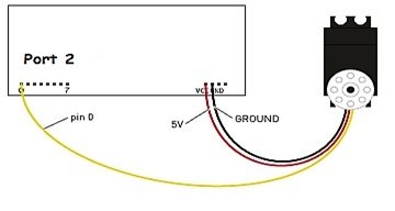
The first two wires are used to give power to the motor. The control signal is connected to the microcontroller to feed PWM signals. Gears and potentiometers control the DC motor in it. A servo motor can turn 90 or 180 degrees in either direction and can go up to 360 degrees. The turning angle depends on the manufacturing process of the servo motor. The servo motor expects a pulse after every 20 ms. The length of the pulse determines how far the motor turns. The shaft angle increases with an increase in pulse width. The duration of that logic 1 pulse can range from 1 ms to 2 ms.
- 1 ms duration pulse can rotate the servo motor to 0 degrees.
- 5 ms duration pulse can rotate it to 90 degrees.
- 2 ms duration pulse can rotate it to 180 degrees.
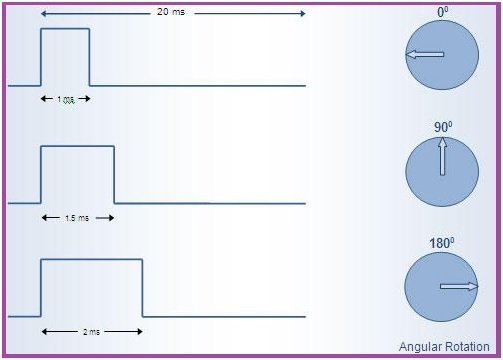
So we can say that pulse durations between 1 ms and 2 ms can rotate a servo motor to any angle that is between 0 and 180 degrees.
Interfacing with 8051 Microcontroller
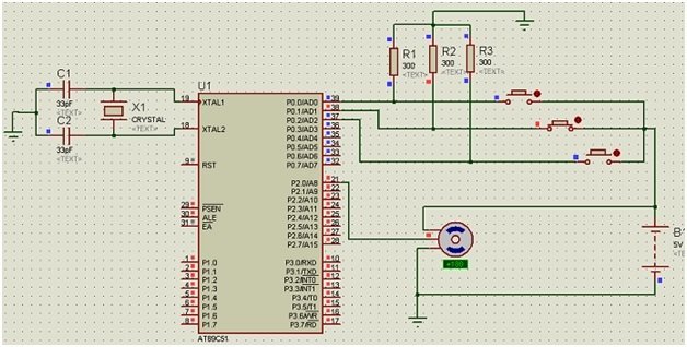
We will control a servo motor with an AT89C51 microcontroller. For this, we connect the servo motor’s red and black wires to the battery and ground, respectively. Its control wire can connect to any port pin of the microcontroller.
Circuit Components
Here we have listed all the components required for this tutorial
- AT89C51 microcontroller
- 12 MHz Oscillator
- 5V DC battery
- Servo motor
- 2 Ceramic capacitors – 33pF
- 300Ω resistors – 3
- Push buttons – 3
Connection of Servo Motor Interfacing with 8051 Microcontroller
| 8051 MCU pins | Connection |
|---|---|
| Pin 1 (Port 2 as output) | Control pin of servo motor. |
| Pin 0, 1 and 2 (Port 0 as output) | 3 Push buttons for manual control of the servo motor. |
| 5 V | input of servo motor. |
Proteus Schematic of Servo Motor Interfacing with 8051 Microcontroller
Here we have provided the Proteus schematic used for simulation.
Working of Servo Motor Interfacing with 8051 Microcontroller
When we start the simulation, the motor will not rotate unless we press a button. If we press the first push button, the servo motor will rotate up to 90 degrees. If we press the second push button, it will rotate up to 180 degrees and stop. And by pressing the third push button, it will rotate up to 270 degrees.
Code of Servo Motor Interfacing with 8051 Microcontroller
In this section, we have provided the code for controlling the servo motor according to the Proteus simulation shown above.
#include <REGX51.H>

void Delay_servo(unsigned int);

sbit control_pin = P2 ^ 0; // Pin0 of port 2
sbit B1 = P0 ^ 0; // Pin 0 of port 0
sbit B2 = P0 ^ 1; // Pin 1 of port 0
sbit B3 = P0 ^ 2; // Pin 2 of port 0

void main()
{
  P0 = 0x07; // input port
  control_pin = 0; // output pin

  do
  {
    if (B1 == 1)
    { //Turn to 90 degree

      control_pin = 1;
      Delay_servo(1218);
      control_pin = 0;

    } else if (B2 == 1)

    { //Turn to 180 degree

      control_pin = 1;
      Delay_servo(1470);
      control_pin = 0;

    } else if (B3 == 1)

    { //Turn to 270 degree

      control_pin = 1;
      Delay_servo(1720);
      control_pin = 0;
    }
  } while (1);
}

void Delay_servo(unsigned int d)
{
  TMOD &= 0xF0; // Clear 4bit field for Timer0
  TMOD |= 0x01; // Set timer0 in mode1, 16bit

  TH0 = 0xFF - (d >> 8) & 0xFF; // Load delay vales Timer 0 + Bitwise right shift[c][d]a >> b
  TL0 = 0xFF - d & 0xFF;

  ET0 = 1; //Enable timer0 interrupts
  EA = 0; // Global Interrupt

  TR0 = 1; // Start timer 0

  while (TF0 == 0); // Wait for overflow
  TR0 = 0; //Stop timer0
  TF0 = 0; // Clear Flag
}
Code Explanation
In this section, we will discuss the working of the code.
#include <REGX51.H>

void Delay_servo(unsigned int);

sbit control_pin = P2 ^ 0; // Pin0 of port 2
sbit B1 = P0 ^ 0; // Pin 0 of port 0
sbit B2 = P0 ^ 1; // Pin 1 of port 0
sbit B3 = P0 ^ 2; // Pin 2 of port 0
Firstly, we add the header tag <REGX51.H>. This will help us deal with the registers of the 8051 microcontroller. Then we declare the pins we need to use. Port 0, lower 3 pins for buttons, and Port 2 pin 0 as a control pin.
void main()
{
  P0 = 0x07; // input port
  control_pin = 0; // output pin

  do
  {
    if (B1 == 1)
    { //Turn to 90 degree

      control_pin = 1;
      Delay_servo(1218);
      control_pin = 0;

    } else if (B2 == 1)

    { //Turn to 180 degree

      control_pin = 1;
      Delay_servo(1470);
      control_pin = 0;

    } else if (B3 == 1)

    { //Turn to 270 degree

      control_pin = 1;
      Delay_servo(1720);
      control_pin = 0;
    }
  } while (1);
}
Secondly, in the void main function, we set port 0 as the input port. Next, we set the control pin as the output pin with low logic. Lastly, we check the button state. The configuration of each button is different, and the conditional statement helps us in a specific case. Button 1 moves the servo motor 90 degrees, while button 2 moves the servo motor 180 degrees. The button 3 moves the servo motor to 270 degrees. The movement of the motor is set via the Delay_servo() function.
void Delay_servo(unsigned int d)
{
  TMOD &= 0xF0; // Clear 4bit field for Timer0
  TMOD |= 0x01; // Set timer0 in mode1, 16bit

  TH0 = 0xFF - (d >> 8) & 0xFF; // Load delay values Timer 0 + Bitwise right shift[c][d]a >> b
  TL0 = 0xFF - d & 0xFF;

  ET0 = 1; //Enable timer0 interrupts
  EA = 0; // Global Interrupt

  TR0 = 1; // Start timer 0

  while (TF0 == 0); // Wait for overflow
  TR0 = 0; //Stop timer0
  TF0 = 0; // Clear Flag
}
Now, moving to the Delay_servo function. This function controls the rotation of the servo motor. Fisrt we initialize few parameters, such as timer0 in mode 1. Then we set the delay values for higher and lower bits of the timer. Then we enable the timer0 interrupt and start the timer. The program checks for the overflow bit and stops the timer. As the timer ends our servo motor will stop moving as well as the control pin gets low.
Applications of Servo Motor Interfacing
- Conveyor Belts: In conveyor belts, the servo motors can control each moment of the belt, i.e., to start, stop, and move the products. e.g., packaging, labeling, and bottling.
- Robotics: Almost every junction of a robot contains a servo motor, which moves the robotic arm at an accurate angle.
- Camera Auto Focus: In cameras, there is a built-in servo motor that is highly accurate and useful in correcting the camera lens to adjust the output of focus pictures.
- Robotic Vehicle: The military organizations use vehicles for bomb detonations; the rotation of the wheels is controlled by the servo motor, which generates sufficient torque to smoothly control the movement as well as the speed of the vehicle.
- Solar Tracking System: In automatic solar panels, servo motors are used to change the angle of the solar plates with the movement of the sun so that the solar panels can continuously face the sun and we can get the maximum power from the system.
- Metal Fabrication Machines: For precise cutting, molding, lathes, grinding, pressing, punching, bending, and centering in metal fabrication, servo motors are considered the backbone.
- Antenna Positioning: For the vertical and horizontal movements of the antennas and telescopes, servo motors provide accurate position and angle.
- Woodworking/CNC: In CNC machines, servo motor applications include cutting and shaping the wood products, as well as drilling holes and auguring, which are necessary for the assembly process.
- Textiles: In the textile industry, servo motors are used to control the weaving machine, spinning machine, knitting machine, and looms; e.g., caps, socks, gloves, carpets, and fabrics are produced by the textile industry.
- Printing Presses/Printers: To start and stop the printer head and at the same time move the paper to accurately draw graphics, pictures, and text, this is also an application of a servo motor. Examples are photographs, newspapers, magazines, and documents.
- Automatic Door Openers: In malls, hospitals, and commercial buildings, servo motors control the automatic movement of the doors by getting an input signal from the pressure plates or by IR.
Conclusion
In this tutorial we have covered the following topics:
- Servo motor and its construction.
- Principle of interfacing servo motor.
- Connection of servo motor.
- Proteus schematic.
- Code and its explanation.
Related Articles
If you liked reading this article, please check out similar content in the links below:
- Servo Motor with Raspberry Pi Pico using MicroPython.
- Interface MG995 Servo Motor with Arduino – Example Code.
- CCPM Servo Consistency Master/Servo Motor Tester.
- SG-90 Servo Motor Interfacing with TM4C123 Launchpad.
- ESP32 Web Server Control Servo motor with Arduino IDE.
- Joystick Based Servo Motor Control using Arduino.
- Servo Motor construction working and control.
This is all for the tutorial, In case you face any difficulties or issues while following this tutorial. Let us know in the comment section below.
WHY YOU USE INTERRUPT WHILE YOU NOT USING TIMER INTERRUPT ISR
I want useTwo servo can you please provide programming please
buddy its 1.5 ms not 5 ms
Thanks for pointing out a mistake. We will update the article.
Good article and helpful post
But I have one query, Can you explain how you have obtain
1218 for 90 Degree
1470 for 180 Degree
1720 for 270 Degree