In this comprehensive guide, we will learn how to interface the BME280 environmental sensor with the Raspberry Pi Pico using MicroPython. The BME280 is a highly accurate and versatile sensor capable of measuring temperature, barometric pressure, and relative humidity simultaneously. This makes it an excellent choice for weather station projects, indoor climate monitoring, altitude estimation, and IoT applications. We will start by exploring the BME280 sensor and its key specifications, then move on to wiring it up with the Raspberry Pi Pico, installing the required MicroPython library, and writing code to read and display sensor data. In the second part of this guide, we will take things further by also connecting an SSD1306 OLED display to show live sensor readings on the screen.

We have a similar guide for ESP32 and ESP8266 using MicroPython:
Prerequisites
Before starting this tutorial, make sure you have the following set up on your system:
- Python 3 installed on your computer
- MicroPython firmware flashed onto your Raspberry Pi Pico
- Thonny IDE installed and configured to communicate with the Pico
If you have not set up MicroPython on your Raspberry Pi Pico yet, follow our getting started guides below:
- Getting Started with Raspberry Pi Pico using Thonny IDE
- Getting Started with Raspberry Pi Pico using uPyCraft IDE
BME280 Sensor Overview
The BME280 is a low-power environmental sensor manufactured by Bosch Sensortec. It can simultaneously measure three environmental parameters: ambient temperature, barometric pressure, and relative humidity. Because it integrates three sensing functions into one compact package, it is widely used in portable electronics, weather monitoring systems, smart home devices, and altitude tracking applications.
One of the standout features of the BME280 is its low power consumption, which makes it ideal for battery-powered IoT devices. It supports two communication protocols: I2C (Inter-Integrated Circuit) and SPI (Serial Peripheral Interface), giving developers flexibility in choosing how to connect it to their microcontroller. In this tutorial, we will use the I2C protocol.
With I2C, the Raspberry Pi Pico acts as the master device, while the BME280 sensor acts as a slave. The master initiates all communication, sending requests to the slave and reading back the measurement data. The BME280 has a default I2C address of 0x76 when the SDO pin is connected to GND, and 0x77 when SDO is connected to VCC. Most commonly available breakout boards use 0x76 by default.
BME280 Key Specifications
Here is a summary of the key technical specifications of the BME280 sensor:
| Parameter | Value |
| Supply Voltage | 1.71V – 3.6V |
| Interface | I2C and SPI |
| I2C Address | 0x76 (default) or 0x77 |
| Temperature Range | -40°C to +85°C |
| Temperature Accuracy | ±1°C |
| Humidity Range | 0% – 100% RH |
| Humidity Accuracy | ±3% RH |
| Pressure Range | 300 – 1100 hPa |
| Pressure Accuracy | ±1 hPa |
| Operating Current | 3.6 µA (typical, normal mode) |
BME280 Pinout Diagram
The figure below shows the BME280 sensor module and its pin labels. Most breakout board modules expose the following four key pins:
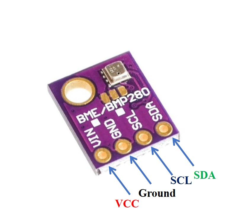
- VCC: Power supply pin. Connect to 3.3V from the Raspberry Pi Pico.
- GND: Ground reference. Connect to the GND pin on the Pico.
- SCL: Serial Clock Line. Used to synchronize data transmission between master and slave.
- SDA: Serial Data Line. Used for bidirectional data exchange between the Pico and the sensor.
Note that some breakout boards also expose a CSB pin (Chip Select for SPI mode) and an SDO pin (which controls the I2C address). In I2C mode, the CSB pin should be connected to VCC and the SDO pin determines the I2C address as mentioned above.
Connecting BME280 to Raspberry Pi Pico
The Raspberry Pi Pico has two hardware I2C controllers — I2C0 and I2C1. Each controller can be mapped to multiple GPIO pins. The table below shows the available I2C GPIO pin options for both controllers:
Raspberry Pi Pico I2C Pins
| I2C Controller | GPIO Pins |
| I2C0 – SDA | GP0/GP4/GP8/GP12/GP16/GP20 |
| I2C0 – SCL | GP1/GP5/GP9/GP13/GP17/GP21 |
| I2C1 – SDA | GP2/GP6/GP10/GP14/GP18/GP26 |
| I2C1 – SCL | GP3/GP7/GP11/GP15/GP19/GP27 |
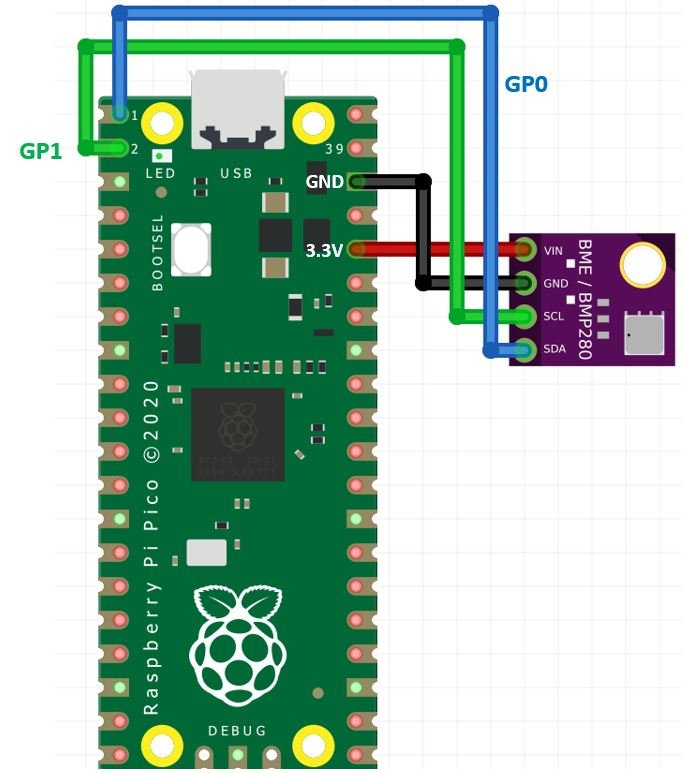
In this tutorial, we will use the I2C0 controller with GP0 as SDA and GP1 as SCL. The wiring connections between the BME280 and the Raspberry Pi Pico are as follows:
| BME280 | Raspberry Pi Pico |
| VCC | 3.3V |
| SDA | GP0 (I2C0 SDA) |
| SCL | GP1 (I2C0 SCL) |
| GND | GND |
You can use any other valid combination of SDA/SCL pins from the table above. Just make sure to update the GPIO pin numbers in your MicroPython code to match your hardware connections. Always double-check that the sensor is powered from the 3.3V pin — connecting the BME280 to 5V can permanently damage it.
Installing the BME280 MicroPython Library
Before writing any code, you need to install the BME280 library for MicroPython on your Raspberry Pi Pico. This library provides ready-to-use functions for initializing the sensor and reading its measurements over I2C. Without it, you would need to manually implement the low-level register communication protocol, which is much more complex.
Follow these steps to install the library using Thonny IDE’s built-in package manager:
- Connect your Raspberry Pi Pico to your computer via a USB cable.
- Open Thonny IDE and make sure it is connected to the Pico (check the bottom-right corner for the interpreter selection).
- Go to Tools > Manage Packages to open the Thonny Package Manager.
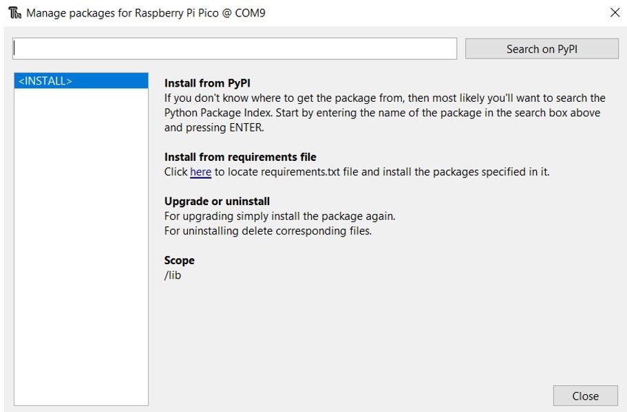
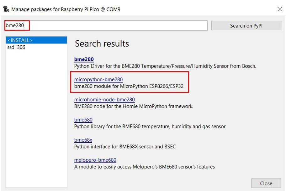
- In the search bar, type bme280 and click the Search on PyPI button.
- From the search results, select micropython-bme280 and click the Install button.
After a few moments, the library will be downloaded and installed onto your Raspberry Pi Pico. You should see a confirmation message in the Thonny output panel. If the installation fails due to a certificate or network error, try restarting Thonny and ensuring your computer is connected to the internet before retrying.
Measuring Temperature, Pressure & Humidity with BME280
With the BME280 library installed, we can now write a MicroPython script to read sensor data from the BME280 and print it to the Thonny shell console. This example is a great starting point for verifying that your hardware wiring is correct and that the sensor is responding properly over I2C.
BME280 MicroPython Code
Copy the following code into a new file in Thonny and save it to the Raspberry Pi Pico as main.py. This script initializes the I2C bus on GP0 and GP1, creates a BME280 object, and then continuously reads and prints temperature, pressure, and humidity values every 10 seconds.
from machine import Pin, I2C        #importing relevant modules & classes
from time import sleep
import bme280       #importing BME280 library

i2c=I2C(0,sda=Pin(0), scl=Pin(1), freq=400000)    #initializing the I2C method
bme = bme280.BME280(i2c=i2c)          #BME280 object created

while True:
  print(bme.values)
  sleep(10)           #delay of 10s
How the Code Works
Let us go through each part of the code step by step to understand how it works.
Importing Libraries
The first step is to import the required modules. The Pin and I2C classes are imported from the machine module, which provides hardware-level access to the Raspberry Pi Pico’s GPIO and communication peripherals. The sleep function is imported from the time module to add a pause between readings. Finally, we import the bme280 library that we installed in the previous step.
from machine import Pin, I2C        #importing relevant modules & classes
from time import sleep
import bme280       #importing BME280 library
Initializing the I2C Bus
Next, we initialize the I2C bus using the I2C()
i2c=I2C(0,sda=Pin(0), scl=Pin(1), freq=400000)Creating the BME280 Object
We then create a BME280 object by calling bme280.BME280(i2c=i2c). This initializes the sensor over the I2C bus and configures it with default settings. The library automatically handles device discovery on the I2C bus and loads the factory calibration data stored inside the sensor’s non-volatile memory. This calibration data is used internally to convert raw ADC readings into accurate physical units.
bme = bme280.BME280(i2c=i2c)Reading and Printing Sensor Values
Inside the infinite while True loop, we call bme.values, which returns a tuple containing three formatted strings: temperature in degrees Celsius, pressure in hectopascals (hPa), and relative humidity as a percentage. The print() function outputs these values to the Thonny shell terminal. After each reading, the script waits 10 seconds before taking the next measurement.
while True:
  print(bme.values)
  sleep(10)           #delay of 10s
Running the Code and Viewing Output
To run the script, click the Save icon in Thonny and choose to save the file to the Raspberry Pi Pico. Name the file main.py so it runs automatically every time the Pico is powered on. Then click the green Run button (or press F5) to execute the script. Make sure the correct interpreter is selected — it should show “MicroPython (Raspberry Pi Pico)” in the bottom-right corner of Thonny.

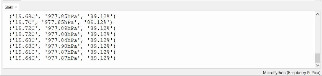
Once running, you will see temperature (°C), pressure (hPa), and humidity (%) values printed in the shell console. Each set of readings will be refreshed every 10 seconds. A typical output looks like this: ('25.32C', '1013.25hPa', '58.40%').
Displaying BME280 Readings on an SSD1306 OLED Display
Now that we have the BME280 sensor working and printing data to the shell console, let us take the project a step further. In this section, we will add a 0.96-inch SSD1306 OLED display and show the temperature, pressure, and humidity readings directly on the screen. This is more practical for standalone deployments where you do not want to rely on a computer or serial terminal to view the data.
You may also like to read:
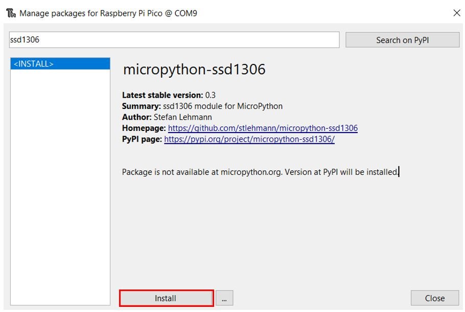
Installing the SSD1306 OLED MicroPython Library
We need to install a second library for the OLED display. The SSD1306 library provides functions to initialize the display, clear the screen, draw text and shapes, and update the display buffer. Follow the same steps as before to install it through Thonny’s Package Manager:
- Open Thonny IDE and go to Tools > Manage Packages.
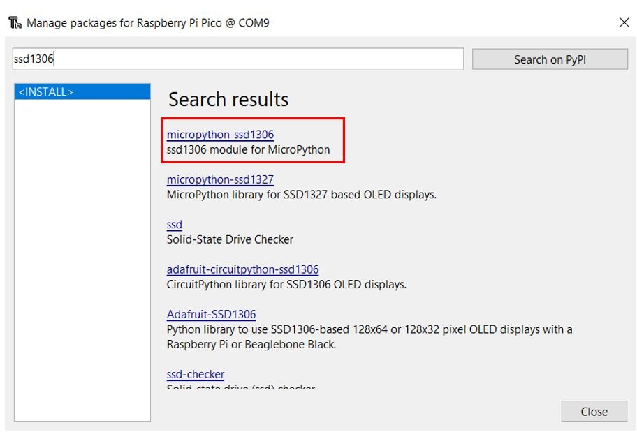
- Type ssd1306 in the search bar and click Search on PyPI.
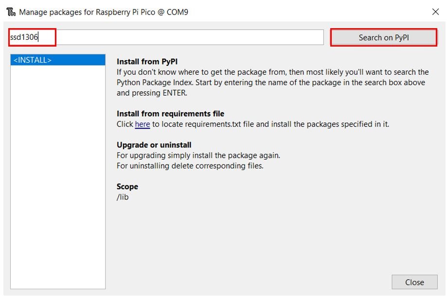
- Select micropython-ssd1306 from the search results.
- Click Install and wait for the installation to complete.
Once installed successfully, you are ready to write the combined code for reading BME280 sensor data and displaying it on the OLED screen.
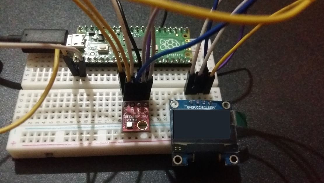
Connecting the OLED Display and BME280 to Raspberry Pi Pico
For this part of the project, you will need the following components:
- Raspberry Pi Pico
- BME280 Sensor module
- 0.96-inch SSD1306 OLED Display (128×64)
- Breadboard
- Jumper wires
Both the BME280 and the SSD1306 OLED display use the I2C protocol, which means they can share the same SDA and SCL lines. This is one of the major advantages of I2C — multiple devices can be connected on the same two-wire bus as long as each device has a unique I2C address. The BME280 uses address 0x76 (or 0x77) and the SSD1306 uses address 0x3C (or 0x3D), so there is no address conflict.
Connect all three devices as follows:
| SSD1306 OLED Display | Raspberry Pi Pico | BME280 |
| VCC | 3.3V | VCC |
| SDA | GP0 (I2C0 SDA) | SDA |
| SCL | GP1 (I2C0 SCL) | SCL |
| GND | GND | GND |
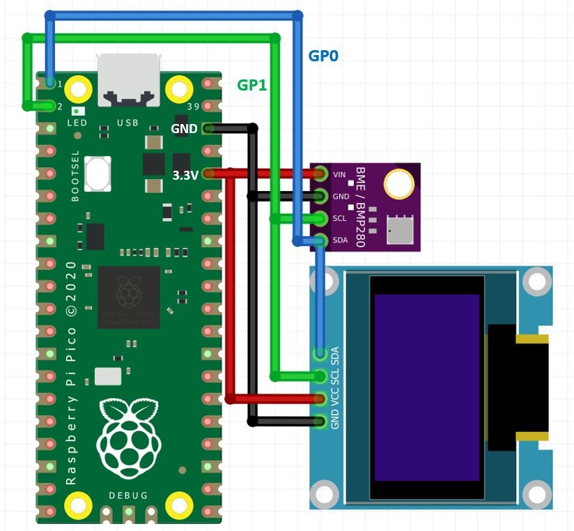
Schematic Diagram: Raspberry Pi Pico with OLED and BME280
Follow the schematic diagram below to connect all three devices correctly. Both the OLED and the BME280 are connected to the same I2C bus (GP0 and GP1).
MicroPython Code: Displaying BME280 Readings on OLED
The following MicroPython script reads temperature, pressure, and humidity values from the BME280 sensor and displays them on the OLED screen. It also prints the readings to the Thonny shell terminal simultaneously.
from machine import Pin, I2C        #importing relevant modules & classes
from time import sleep
import bme280        #importing BME280 library
from ssd1306 import SSD1306_I2C

i2c=I2C(0,sda=Pin(0), scl=Pin(1), freq=400000)    #initializing the I2C method
oled = SSD1306_I2C(128, 64, i2c)
bme = bme280.BME280(i2c=i2c)        #BME280 object created

while True:
  oled.fill(0)
  temperature = bme.values[0]         #reading the value of temperature
  pressure = bme.values[1]            #reading the value of pressure
  humidity = bme.values[2]            #reading the value of humidity

  print('Temperature: ', temperature)    #printing BME280 values
  print('Humidity: ', humidity)
  print('Pressure: ', pressure)

  oled.text("Temp: "+temperature, 0, 0)
  oled.text("PA: "+pressure, 0, 20)
  oled.text("Hum: "+humidity, 0,40)
  oled.show()                          #display
  sleep(10)     #delay of 10s
How the Code Works
Let us walk through the key parts of this code:
Importing Libraries
In addition to the previously used modules, we now also import the SSD1306_I2C class from the ssd1306 library. This class provides all the methods needed to control the OLED display over I2C.
from ssd1306 import SSD1306_I2CInitializing the OLED Display
The I2C bus object i2c is shared between both the BME280 and the OLED display. We create an SSD1306_I2C object by passing the display width (128 pixels), height (64 pixels), and the shared i2c object as arguments. The library uses these to configure the display driver and set up the frame buffer in memory.
oled = SSD1306_I2C(128, 64, i2c)Clearing the Display
At the beginning of each loop iteration, we call oled.fill(0) to clear the display by filling it with black pixels (value 0 = off). This ensures that old readings do not overlap with the new ones. If you skip this step, text from previous iterations will remain on screen.
oled.fill(0)Reading Sensor Values
We access the BME280 readings using the bme.values property, which returns a tuple with three string elements. Index 0 is temperature (e.g., “25.32C”), index 1 is pressure (e.g., “1013.25hPa”), and index 2 is humidity (e.g., “58.40%”). These values are stored in separate variables for use in both printing and OLED display.
temperature = bme.values[0]
pressure = bme.values[1]
humidity = bme.values[2]
Displaying Text on the OLED
The oled.text() method accepts three arguments: the string to display, the x-coordinate (column), and the y-coordinate (row) in pixels. We place the temperature at y=0 (top of screen), pressure at y=20 (middle), and humidity at y=40 (lower section). After setting all text, we call oled.show() to push the frame buffer to the display hardware and actually render the text on screen.
oled.text("Temp: "+temperature, 0, 0)
oled.text("PA: "+pressure, 0, 20)
oled.text("Hum: "+humidity, 0, 40)
oled.show()
sleep(10)
Demonstration
Upload the code to your Raspberry Pi Pico by saving it as main.py on the device and pressing the Run button in Thonny. Once running, you will see the BME280 temperature, pressure, and humidity values displayed on the OLED screen, updating every 10 seconds:
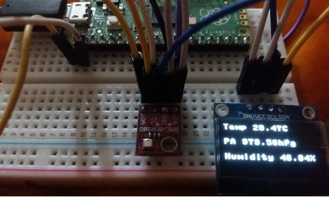
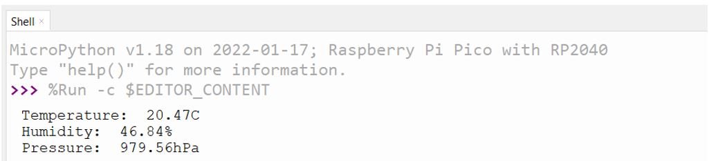
The Thonny shell terminal will simultaneously display the same readings in text format:
Troubleshooting Common Issues
If you encounter problems while running this project, here are some common issues and how to resolve them:
OSError: [Errno 5] EIO or no I2C device found: This usually means the wiring is incorrect or the sensor is not being detected on the I2C bus. Double-check that VCC is connected to 3.3V (not 5V), GND is shared between all components, and SDA/SCL are correctly connected to GP0 and GP1. You can run an I2C scan using print(i2c.scan()) to see which device addresses are detected. You should see [118] (0x76) for BME280 and [60] (0x3C) for the OLED.
Module not found — bme280 or ssd1306: This means the library was not installed correctly on the Pico. Reconnect the Pico, reopen Thonny, and repeat the installation steps from the Package Manager. Confirm that Thonny is set to use the MicroPython interpreter on the Pico, not the local Python on your computer.
OLED not displaying anything: Make sure you call oled.show() after drawing text. Without this call, the changes remain in the frame buffer and are never sent to the display. Also verify the OLED is receiving 3.3V power and that its I2C address matches what the library expects.
Incorrect or erratic readings: If temperature readings seem unexpectedly high, the sensor may be self-heating due to close proximity to power components. The BME280 should ideally be placed away from heat sources for accurate ambient temperature measurements.
We have other guides featuring popular sensors with the Raspberry Pi Pico:
- HC-SR04 Ultrasonic Sensor with Raspberry Pi Pico using MicroPython
- MPU6050 with Raspberry Pi Pico (Accelerometer, Gyroscope, and Temperature)
- DHT11 DHT22 with Raspberry Pi Pico using MicroPython
- DS18B20 Temperature Sensor with Raspberry Pi Pico using MicroPython
You may also like to read other BME280-related articles:
- BME280 Data Logger with Arduino and Micro SD Card
- ESP32 MQTT Client: Subscribe and Publish BME280 sensor readings on HiveMQ
- BME280 Web Server with ESP32 (Arduino IDE)
- Telegram ESP32/ESP8266: Display BME280 sensor readings using Arduino IDE
- BME280 Web Server with ESP8266 NodeMCU (Arduino IDE)
- ESP8266 NodeMCU Send Sensor Readings to ThingSpeak using Arduino IDE (BME280)
- ESP32 Send Sensor Readings to ThingSpeak using Arduino IDE (BME280)
Works also with the adafruit BME280 (p2652)
but you need the I2C address to 0x77 in lib/bme280.py (line 41)
I ran into the same issue – OSError: [Errno 5] EIO – I can confirm this is the fix.
apparently, you need to wire it up on the same bus (using a breadboard). You cannot, as far as I have learned, use two different sets of GPIO pins. Odd.
Hi there,
when I run the above code, I always get the following error:
Traceback (most recent call last):
File “”, line 1, in
File “/lib/bme280.py”, line 75, in __init__
OSError: [Errno 5] EIO
Has somebody else encountered this issue and found a solution? I tried it with MicroPython 1.9.1 and 1.8.1
Never mind, i2c was connected at the wrong pins.
HI,
Looking for help in resolving this error. I see it come up every time I attempt to work with the BME280.
MPY: soft reboot
Traceback (most recent call last):
File “”, line 9, in
File “bme280.py”, line 74, in __init__
OSError: [Errno 5] EIO
9: bme = bme280.BME280(i2c=i2c) #BME280 object created
73 # load calibration data
74 dig_88_a1 = self.i2c.readfrom_mem(self.address, 0x88, 26)
I have the same issue.
Did you find a resolution?
Well on the webpage you create inside the loop the object bme.
The creation of the object should be outside the loop!
you need to create the object only once!
It should be
bme = bme280.BME280(i2c=i2c) #BME280 object created
while True:
print(bme.values)
sleep(10)
Even this is strange because you need to read the values somehow
I’m using this
t, p, h = bme.read_compensated_data()
to read temperature,pressure and humidity
in our case, it does not require to create object outside loop.
Well re-creating the object all the time start to partialise the stack after a while you could have a problem recreating the object. And why making a new object all the time. You made it once and get around problem with the memory stack.
Hi Daniel,
Yes you are right. Thank you for pointint out a mistake, we have just fixed it. Thanks
Thonny 4.1.4. Tools>Manage Package does not give any result when bme280 or BME280 is typed in into the searchbox.
Typing in SSD1306. This one is found.
How can I solve it?
Version of Thonny was the problem.
With Thonny v.4.1.7 BME280 package can be installed.