In this tutorial, we will learn how to use GPIO pins of ESP8266 NodeMCU module as output pins as well as input pins. Accordingly, we will also show how to interface an LED controlled via a push button with the ESP8266 board. We will be reading the value from the Push Button and lighting up the LED consequently. Here the Push button’s terminal will act as a digital input and the LED will act as a digital output.
The Push button will be used to control device like turning ON and OFF a light-emitting diode when the push button is pressed or not. Similarly, we can use push button to increase or decrease speed of dc motor. When you use the push button with ESP8266, we have to use GPIO pins as digital input pins. Because we will read the state of the push button.The push button will give two logical states either high or low.
Prerequisites
We will use Arduino IDE to program our ESP8266 development boards. Thus, you should have the latest version of Arduino IDE. Additionally, you also need to install the ESP8266 plugin. If your IDE does not have the plugin installed you can visit the link below:
Installing ESP8266 library in Arduino IDE and upload code
GPIO Pins of ESP8266 as Digital Input and Output
GPIO pins act as both input and output pins with an exception for a few. We will be using the GPIO Pins as digital input and as digital output pins in our ESP8266 board this time when connecting the push button and the LED respectively. One digital pin will be connected to the push button and another one for the LED. We will be taking in the digital input from the push button and acquire the digital output from the LED.
Below is the diagram showing the GPIO pins for ESP8266 which we will be using to connect the push button and the LED
ESP8266 GPIO Pinout
For in-depth details on pinout and GPIO pins of ESP8266 NodeMCU Kit, check the following tutorial:
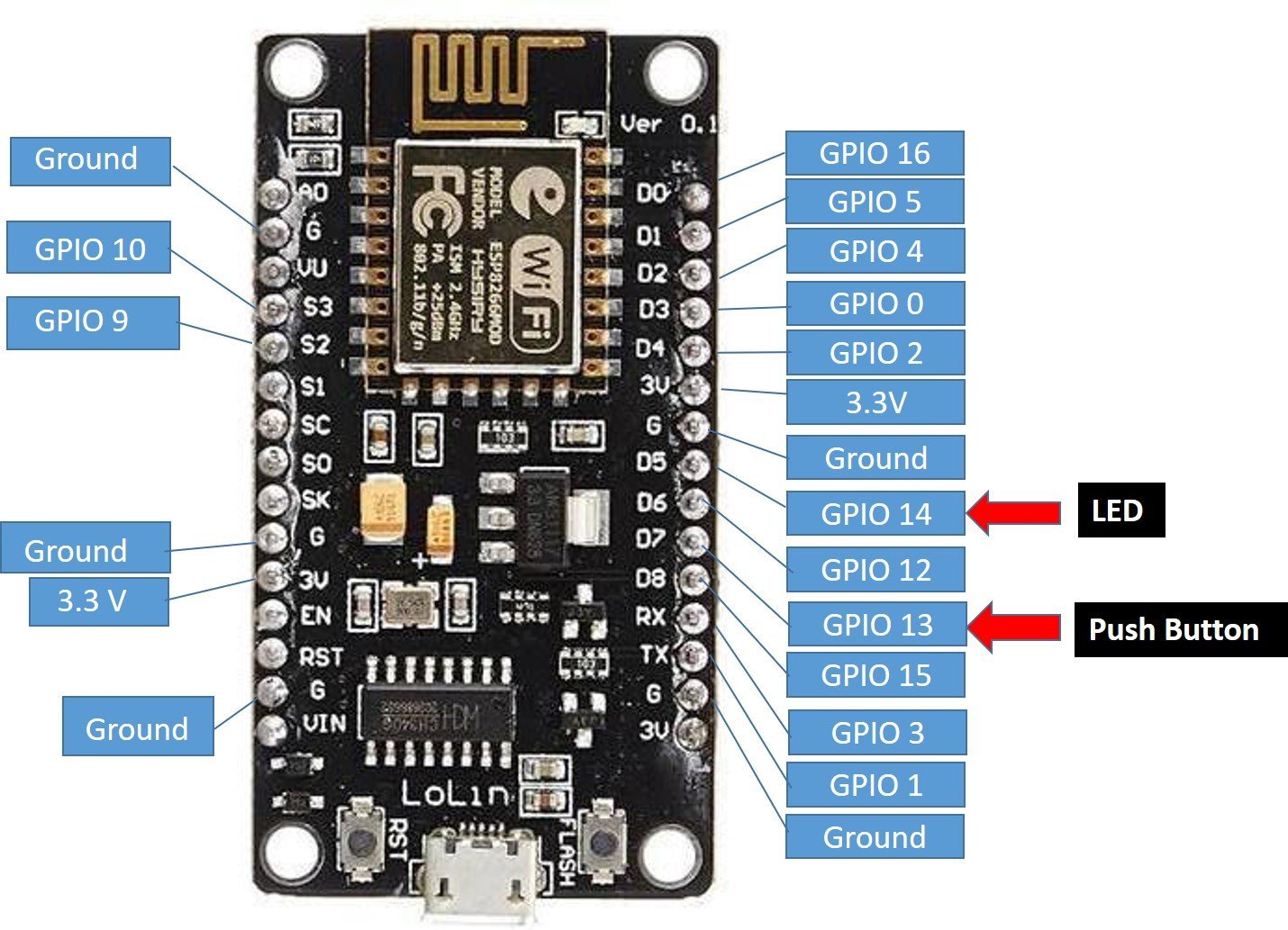
As shown in the above diagram we will be using GPIO 14 (D5) to connect the LED and GPIO 13 (D7) to connect the push button.
Push Button Interfacing ESP8266 using Arduino IDE
We will read the state of the push button. The push button will give two logical states either high or low. We will connect the push button with the ESP8266 board using a resistor.
There are two types of resistors that can be used in this project. Pull-up and pull-down resistors. We will be using Pull- down resistors which work on the principle that whenever the push button is pressed, the input to GPIO pin will be logic high state (1) and otherwise logic low state (0). If it is a logic state high that means 1 the LED would switch on and if the logic state is low that means 0 then the LED is off. It works vice-versa if we use pull-up resistors instead.
Connection Diagram
Assembling the Circuit of Push button with ESP8266. Now we will connect the circuit with the LED and push button. The following components are required.
Required Components:
- ESP8266 module
- One LED
- 220 ohm resistor
- 10k ohm resistor
- Breadboard
- Connecting wires
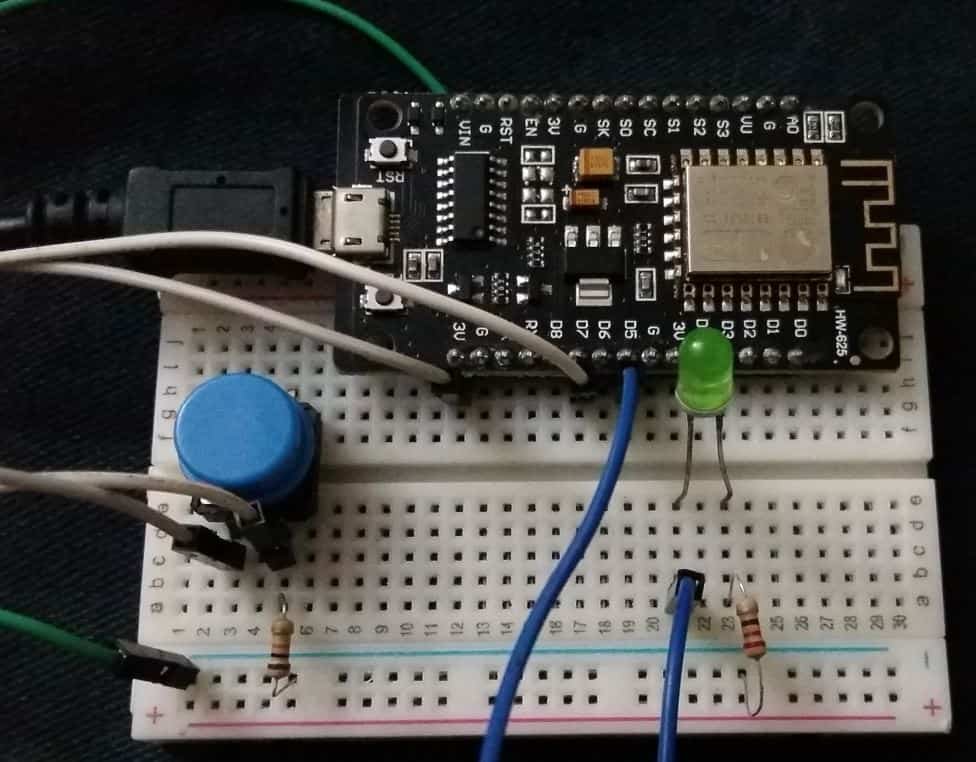
The below picture shows the schematic for ESP8266 module with a push button and LED. Assemble your circuit as follows:

In the above schematic, we can see that GPIO 14 is connected with the anode pin of LED, and the cathode pin is connected with the common ground through the 220-ohm resistor.
The push-button has four terminals. One terminal is powered by 3.3 volts from ESP8266 and the other terminal is connected by GPIO 13 and the 10k ohm resistor which acts as a pull-down resistor. The other end of the resistor is connected with the common ground.
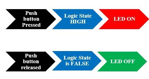
When the push button is pressed, a logic state of high (1) will be passed on GPIO13 and the push button input will be in a high state. When the button is released a logic state of low (0) will be passed on GPIO13 and the push button input will be in a logic state LOW. We will read these two states of the push button and turn on and turn off the LED accordingly.
Arduino Sketch: ESP8266 Control Digital Output (LED) through Reading Digital Input (Push Button state)
Open your Arduino IDE and go to File > New. A new file will open. Copy the code given below in that file and save it.
const int Push_button_pin = 13;
const int led =  14;
int Push_button_state = 0;

void setup() {
  pinMode(Push_button_pin, INPUT);
  pinMode(led, OUTPUT);
}

void loop() {

  Push_button_state = digitalRead(Push_button_pin);
  if (Push_button_state == HIGH) {
    digitalWrite(led, HIGH);
  } else {
    digitalWrite(led, LOW);
  }
}
How the Code Works?
Firstly, we will define the GPIO pins connected with both the LED and push button in two different variables. In our case the push button is conncted with GPIO13 and the LED is connected with GPIO14.
*Note: The GPIO number on ESP8266 does not match the label which is printed on the board. As an example, D5 corresponds to GPIO 14 and D7 corresponds to GPIO 13. So be careful while coding because in the program code we will use the GPIO number not the number which is imprinted on the board for proper functionality.
const int Push_button_pin = 13;
const int led =  14;
Next, we will define another variable that will hold the push button state. Initially it is set to 0.
int Push_button_state = 0;Configuring Digital Input and Output
In setup() function, we use pinMode() function to initialize Push_button_pin as an INPUT and led as an INPUT. The pinMode() function takes in two parameters. The first parameter is the pin number and the second is INPUT/OUTPUT.
void setup() {
  pinMode(Push_button_pin, INPUT);
  pinMode(led, OUTPUT);
}
Reading Digital Input and Controlling Digital Output
In loop() function, digitalRead function will read the state of the push button and store its value in variable Push_button_state. The digitalRead(PIN) function is used to read the state of the input pin. It returns either logical HIGH or logical LOW input. If input state of the pin is HIGH, it will return HIGH and otherwise low. You only need to pass pin number as a augment to this function. For example in this tutorial, we are using pin number 13 as a digital input, so we will use this function like this digitalRead(13).
Push_button_state = digitalRead(Push_button_pin);After that, if condition is used to check the state of variable Push_button_state.
If Push_button_state gives output HIGH, the LED will be turned ON and otherwise, it will remain OFF. We will use the digitalWrite() function to control the digital output that is LED in our case. This function takes in two parameters. The first parameter is the GPIO pin connected with the LED and the second is the state of the pin (LOW/HIGH).
void loop() {

  Push_button_state = digitalRead(Push_button_pin);
  if (Push_button_state == HIGH) {
    digitalWrite(led, HIGH);
  } else {
    digitalWrite(led, LOW);
  }
}
Demonstration
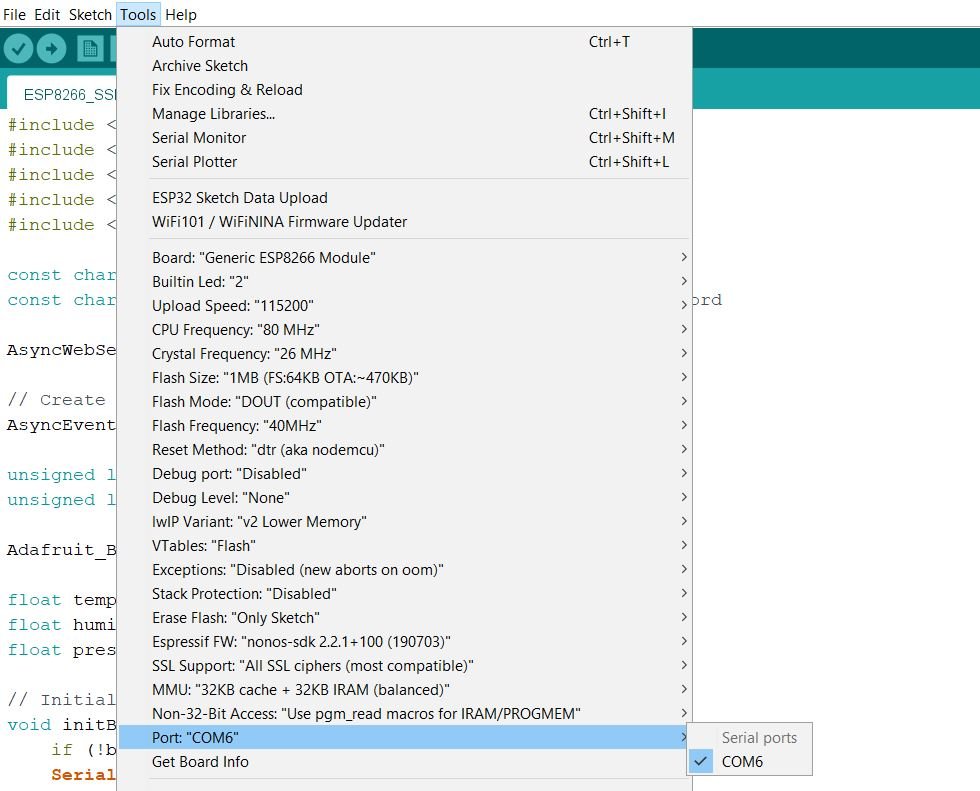
Choose the correct board and COM port before uploading your code to the board. Go to Tools > Board and select NodeMCU 1.0

Next, go to Tools > Port and select the appropriate port through which your board is connected.
Click on the upload button to upload the code into the ESP8266 development board.
After you have uploaded your code to the development board, press its RST button.

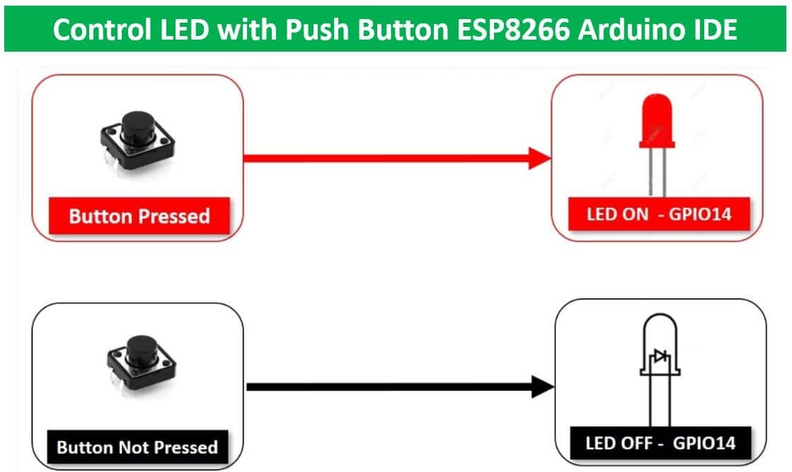
Now press the push button and the LED will turn ON.

Releasing the button will turn it OFF.
Conclusion
In this tutorial, we have learned how to use ESP8266 NodeMCU GPIO pins as both inputs and outputs in the same project by controlling the ON/OFF state of an LED using a push-button using Arduino IDE. For further similar articles go through the links given below:
- Push button with ESP32 – GPIO pins as digital input
- Push Button with ESP32 and ESP8266 using MicroPython – Control an LED
More ESP8266 NodeMCU tutorials:
Can anyone give me a circuit for sine/cos input and TTL output please.
For A and B encoder signals
I would be most grateful
Regards
Paul ABS Measurement CC South Africa