In this tutorial, we are going to look at how to blink an LED using the ATmega32 AVR microcontroller. This article will discuss the basics of programming an AVR ATmega32. We will learn how to develop codes for blinking LEDs using the ATmega32. You will also learn how to determine the direction of I/O pins and how to make the status of output pins high or low.
In case this is your first time working with the ATmega32 AVR microcontroller and Atmel Studio 6, you might want to check out these tutorials first: Atmel Studio 6 tutorial step-by-step guide and ATmega32 microcontroller
Write LED Blinking Code for AVR Microcontroller
Firstly, we will develop the code for “LED blinking” using Atmel Studio 6. Then, we will upload this code to the ATmega32 microcontroller and test the results. Here, we will write code using the C language. For the programming of the AVR ATmega32, two registers are used: DDR and PORT. DDR is a data direction register that indicates whether the pin of the ATmega32 is set as an input or output, while the PORT register is an output register that determines whether the pin of the corresponding port is active low (0V) or active high (5V).

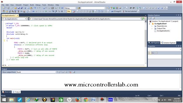
For writing code, open Atmel Studio 6, select “New Project” and choose “GCC C Executable Project”. After selecting “Device”, the main C window will open, and here we can write our code.
AVR Microcontroller LED Blinking Code
The codes for blinking all LEDs and blinking LEDs one by one are given below.
For Blinking All LEDs
The code given below is written using AVR Studio 6. In this program, we will turn all LEDs connected with Port D on and off in sync.
#ifndef F_CPU
# define F_CPU 16000000 UL // clock speed is 16MHz
#endif

#include <avr/io.h>
#include <util/delay.h>

int main(void)
{
  DDRD = 0xFF; // declared port D as output

  while (1) // initialize infinite while loop
  {
    PORTD = 0xFF; // turn on all LEDs of PORTD
    _delay_ms(1000); // delay of one second

    PORTD = 0x00; // turn off all LEDs of PORTD
    _delay_ms(1000); // delay of one second
  } // while loop end
} // main end
Code Explanation
Here, we will explain the workings of the above code.
#ifndef F_CPU
# define F_CPU 16000000 UL // clock speed is 16MHz
#endif

#include <avr/io.h>
#include <util/delay.h>
Firstly, we define the clock speed of the ATmega32 microcontroller. After this, we include header tags <avr/io.h> to deal with inputs and outputs of the AVR ATmega32 microcontroller and <util/delay> to handle the delay of the AVR ATmega32.
int main(void)
{
  DDRD = 0xFF; // declared port D as output
Secondly, in the main function, we declare port D of the ATmega32 as the output port.
  while (1) // initialize infinite while loop
  {
    PORTD = 0xFF; // turn on all LEDs of PORTD
    _delay_ms(1000); // delay of one second

    PORTD = 0x00; // turn off all LEDs of PORTD
    _delay_ms(1000); // delay of one second
  } // while loop end
} // main end
Lastly, we initiate a while loop. In this while loop, we set Port D to high using the 0xFF command. After this, we add a delay of 1000 ms or 1 second. Next, we set the Port D pins to low using the 0x00 command with a delay of 1 second. Then we end the while loop and the main function.
This program turns the Port D pins to high and low after 1 second, and the LEDs connected to Port D will blink in sync.
AVR Microcontroller Alternate LED Blinking Code
The code given below is written using AVR Studio 6. In this program, we will turn all LEDs connected to Port D on and off one by one.
#ifndef F_CPU
#define F_CPU 16000000 UL //clock speed is 16MHz
#endif

#include <avr/io.h>
#include <util/delay.h>

int main(void) //main starts
{
  DDRD = 0b11111111; // declaring port D as output
  while (1) // initialize infinite while loop
  {

    PORTD = 0b10000000; // pin 0 of port D set HIGH
    _delay_ms(1000); // delay of one second

    PORTD = 0b01000000; // pin 1 of port D set HIGH
    _delay_ms(1000); // delay of one second

    PORTD = 0b00100000; // pin 2 of port D set HIGH
    _delay_ms(1000); // delay of one second

    PORTD = 0b00010000; // pin 3 of port D set HIGH
    _delay_ms(1000); // delay of one second

    PORTD = 0b00001000; // pin 4 of port D set HIGH
    _delay_ms(1000); // delay of one second

    PORTD = 0b00000100; // pin 5 of port D set HIGH
    _delay_ms(1000); // delay of one second

    PORTD = 0b00000010; // pin 6 of port D set HIGH
    _delay_ms(1000); // delay of one second

    PORTD = 0b0000001; // pin 7 of port D set HIGH
    _delay_ms(1000); // delay of one second
  } // while loop end
} //main end
Code Explanation
Here, we will explain the workings of the above code.
#ifndef F_CPU
#define F_CPU 16000000 UL //clock speed is 16MHz
#endif

#include <avr/io.h>
#include <util/delay.h>
Firstly, we define the clock speed of the ATmega32 microcontroller. After this, we include header tags <avr/io.h> to deal with inputs and outputs of the AVR ATmega32 microcontroller and <util/delay> to handle the delay of the AVR ATmega32.
int main(void) //main starts
{
  DDRD = 0b11111111; // declaring port D as output
  while (1) // initialize infinite while loop
  {

    PORTD = 0b10000000; // pin 0 of port D set HIGH
    _delay_ms(1000); // delay of one second

    PORTD = 0b01000000; // pin 1 of port D set HIGH
    _delay_ms(1000); // delay of one second

    PORTD = 0b00100000; // pin 2 of port D set HIGH
    _delay_ms(1000); // delay of one second

    PORTD = 0b00010000; // pin 3 of port D set HIGH
    _delay_ms(1000); // delay of one second

    PORTD = 0b00001000; // pin 4 of port D set HIGH
    _delay_ms(1000); // delay of one second

    PORTD = 0b00000100; // pin 5 of port D set HIGH
    _delay_ms(1000); // delay of one second

    PORTD = 0b00000010; // pin 6 of port D set HIGH
    _delay_ms(1000); // delay of one second

    PORTD = 0b0000001; // pin 7 of port D set HIGH
    _delay_ms(1000); // delay of one second
  } // while loop end
} //main end
In the void main function, first we declare port D as the output port. Then, in the ‘while loop’, we turn one pin of Port D high at a time while the other pins are kept low. We do this for each pin from 0 to 7, with a delay of 1 second. Lastly, we end the while loop and the main function.
This program turns the Port D pins to high and low after 1 second, and the LEDs connected to Port D will turn on one at a time while the others will be off.

After writing the code, we will compile it and save this file.
Proteus Circuit Simulation LED Blinking
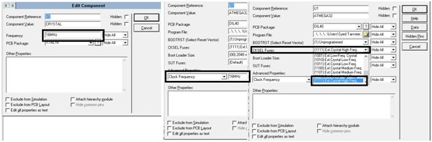
To observe the working of this code, simulate the circuit on Proteus by using the ATmega32, 8 LEDs, registers, capacitors, and crystal from the built-in library of Proteus. Notice that the ground and Vcc (voltage supply) pins of the ATmega32 are connected by default in Proteus. While working in real time, you have to connect the VCC with the 5V and ground pins. Set the frequency of the crystal oscillator and ATmega32 to “16 MHz” and set the fuse bits.
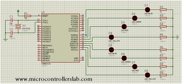
Circuit Schematic
Here we have provided the circuit diagram for blinking one LED at a time, which is given below.
When the Proteus circuit is complete, double-click on the ATmega32 IC to load the HEX file of the code.
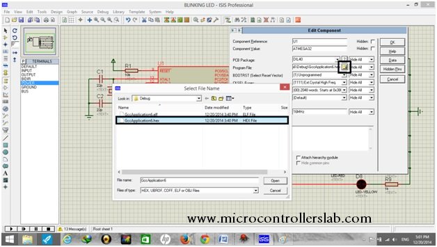
After uploading the HEX file, click the play button present in the bottom left corner. The blinking LEDs will show the result.

Conclusion
In this article, we have discussed the following topics:
- Introduction and developing the code.
- Codes with an explanation.
- Circuit schematic with Proteus simulation
Related Articles
You may also like to read:
When i uploaded that code the delay was closer to 15 seconds even though i stated 1000 inside delay_ms. Why is that?
Check your crystal oscillator settings or if you are using external make sure to use the correct value.
Can we make this code shorter?
Good day, i`m asking for tutorials for using micro Python on any microcontrollers
Please check here:
https://microcontrollerslab.com/category/raspberry-pi-pico/