In this guide, we will introduce you to Arduino watchdog timer. The ATmega328P chip is used to operate the Arduino UNO board. The Watchdog Timer on the ATmega328P is a crucial tool for helping the system recover from instances where the system hangs or freezes due to faults in the code or conditions caused by hardware difficulties. Let us discuss this briefly.
Recommended Components
The following components are used in this project or are helpful for building it with the Arduino.
| Component | How it’s used in this project | Buy on Amazon |
|---|---|---|
| Arduino Uno R3 | The main controller board whose watchdog timer is configured and demonstrated in this tutorial. | Check Price |
| Breadboard | Solderless board to build the simple demo LED circuit. | Check Price |
| Jumper Wires | Used to wire the demo LED and resistor to the Arduino. | Check Price |
| 5mm LED | The indicator LED used to show watchdog resets and normal operation in the example. | Check Price |
| Resistor Kit (220/4.7k) | Provides the current-limiting resistor in series with the demo LED. | Check Price |
As an Amazon Associate we earn from qualifying purchases. Prices and availability are accurate as of the date/time indicated and are subject to change.
Arduino Watchdog
As we mentioned before, the ATmega328P chip features a useful watchdog timer that helps in the prevention of system failures by resetting the system or calling an assigned function to the watchdog. The watchdog can be triggered as a reset or as an interrupt. In case of a watchdog interrupt, it can also work as a system timer.
A separate on-chip oscillator clocks the watchdog. The watchdog reset timer may be configured from 16ms to 8s using a Prescaler. Temperature and operating voltage affect the clock frequency generated by the on-chip oscillator, therefore expectations of consistency must be maintained to a minimum. As a result, the watchdog is less suited to time-sensitive duties.
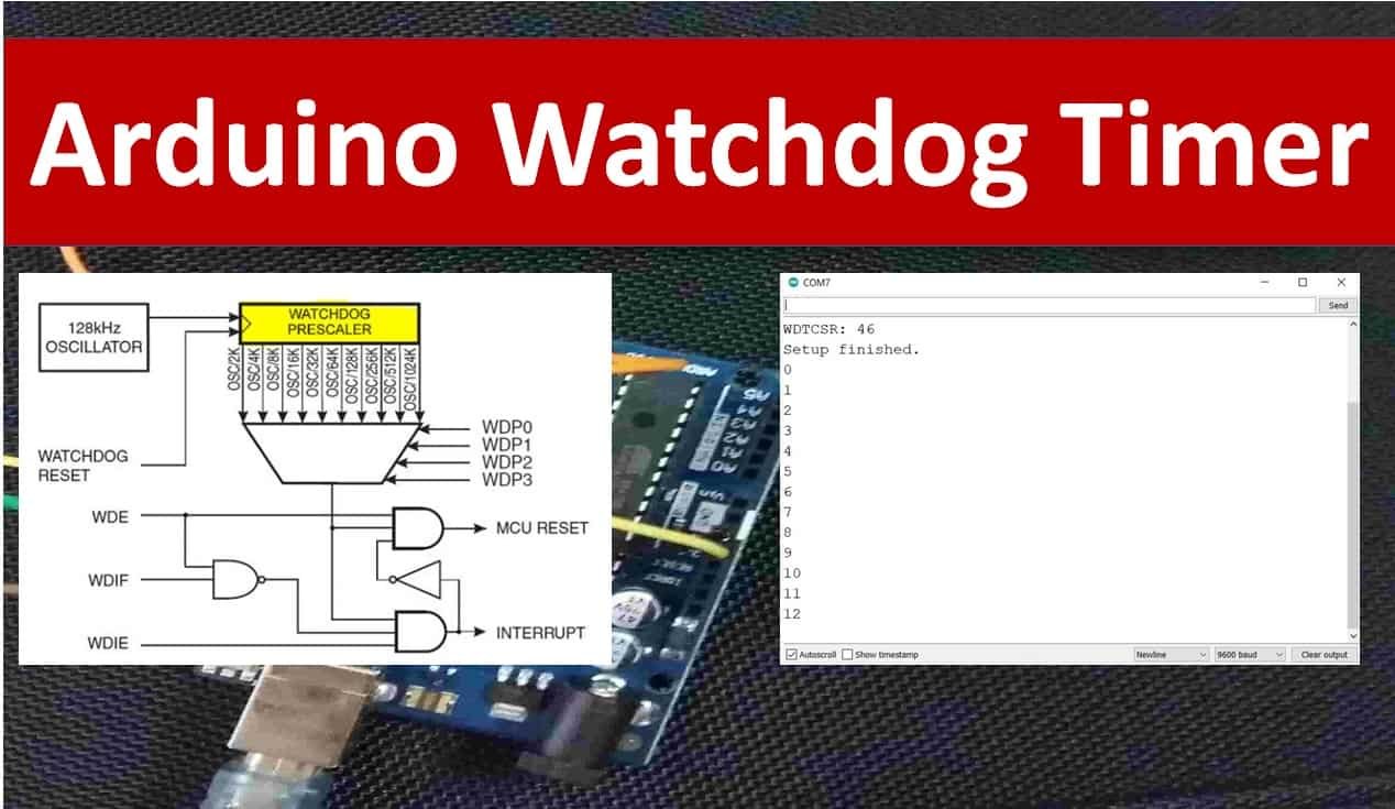
The block diagram below shows the watchdog in ATmega328P:

Watchdog Timer Control Registers
The watchdog timer is managed by the WDTCSR register as shown below. All the bits except bit 7 (read only) are readable and writable. The watchdog timer with all the register and controls bits are shown below.
| Bit | 7 | 6 | 5 | 4 | 3 | 2 | 1 | 0 | |
| (0x60) | WDIF | WDIE | WDP3 | WDCE | WDE | WDP2 | WDP11 | WDP0 | WDTCSR |
| Read/Write | R | R/W | R/W | R/W | R/W | R/W | R/W | R/W | |
| Initial Value | 0 | 0 | 0 | 0 | 0 | 0 | 0 | 0 |
To find the time-out period, refer to the table below to set the WDP3, WDP2, WDP1 and WPD0 bits.
| WDP3 | WDP2 | WDP1 | WDP0 | Oscillator Cycle | Time-out |
| 0 | 0 | 0 | 0 | 2K | 16ms |
| 0 | 0 | 0 | 1 | 4K | 32ms |
| 0 | 0 | 1 | 0 | 8K | 64ms |
| 0 | 0 | 1 | 1 | 16K | 0.125s |
| 0 | 1 | 0 | 0 | 32K | 0.25s |
| 0 | 1 | 0 | 1 | 64K | 0.5s |
| 0 | 1 | 1 | 0 | 128K | 1s |
| 0 | 1 | 1 | 1 | 256K | 2s |
| 1 | 0 | 0 | 0 | 512K | 4s |
| 1 | 0 | 0 | 1 | 1024K | 8s |
To configure the watchdog, follow the table below:
| WDTON Fuse | WDE | WDIE | Mode | Action |
| 1 | 0 | 0 | Stop | No |
| 1 | 0 | 1 | Interrupt | Interrupt |
| 1 | 1 | 0 | System Reset | System Reset |
| 1 | 1 | 1 | Interrupt + System Reset | Interrupt -> System Reset |
| 0 | x | x | System Reset | System Reset |
Arduino Watchdog Interrupt Sketch
Open your Arduino IDE and go to File > New to open a new file. Copy the code given below in that file.
This sketch demonstrates the watchdog interrupt which toggles the onboard LED of Arduino that is connected with pin13.
// Title : Watchdog
// Author : Claus Kuehnel <ckuehnel@gmx.ch>
// Date : 2017-05-10
// Id : watchdog.ino
// Tested w/ : Arduino 1.8.0
//
// DISCLAIMER:
// The author is in no way responsible for any problems or damage caused by
// using this code. Use at your own risk.
//
// LICENSE:
// This code is distributed under the GNU Public License
// which can be found at http://www.gnu.org/licenses/gpl.txt
//
// Definition of interrupt names
#include <avr/io.h>
// ISR interrupt service routine
#include <avr/interrupt.h>
#define wdt_reset() __asm__ __volatile__ ("wdr")
const int pLED = 13; // LED at Pin13
int idx;

// Install the interrupt routine for Watchdog Interrupt
ISR(WDT_vect)
{
flash();
}
void setup()
{
Serial.begin(9600);
pinMode(pLED, OUTPUT);
digitalWrite(pLED, LOW);
cli();
wdt_reset();
WDTCSR |= (1<<WDCE) | (1<<WDE); // Start timed sequence
WDTCSR = (1<<WDIE) | (1<<WDP2) | (1<<WDP1); // Set new prescaler = 128K cycles(~1 s)
sei();
Serial.print("WDTCSR: ");
Serial.println(WDTCSR, HEX);
Serial.println("Setup finished.");
}
void loop()
{
Serial.println(idx++); // do anything
delay(1500); // change argument to 1500 -> watchdog will be active
wdt_reset();
}
void flash()
{
static boolean output = HIGH;
digitalWrite(pLED, output);
output = !output;
}
How the Code Works?
Firstly, include the definition of the interrupt names and the ISR interrupt service routine.
#include <avr/io.h>
#include <avr/interrupt.h>
The watchdog reset is specified as an inline assembler statement by the macro wdt_reset(). This must be executed by the application before the configured watchdog period has ended.
#define wdt_reset() __asm__ __volatile__ ("wdr")Create two variables. ‘pLED’ to hold the Arduino pin connected with the onboard LED and ‘idx’ will be incremented inside the main program.
const int pLED = 13; // LED at Pin13
int idx;
This is the interrupt service routine for the watchdog interrupt:
ISR(WDT_vect)
{
flash();
}
The flash() function is used to toggle the LED when an interrupt is triggered.
void flash()
{
static boolean output = HIGH;
digitalWrite(pLED, output);
output = !output;
}
Inside the setup() function, open the serial communication at the set baud rate. Configure the led pin as an output pin and set its value to LOW. Call the wdt_reset() function, to reset the watchdog timer. Next, an approximate time-out period of 1s is set by initializing the watchdog register WDTCSR according to the table given previously.
void setup()
{
Serial.begin(9600);
pinMode(pLED, OUTPUT);
digitalWrite(pLED, LOW);
cli();
wdt_reset();
WDTCSR |= (1<<WDCE) | (1<<WDE); // Start timed sequence
WDTCSR = (1<<WDIE) | (1<<WDP2) | (1<<WDP1); // Set new prescaler = 128K cycles(~1 s)
sei();
Serial.print("WDTCSR: ");
Serial.println(WDTCSR, HEX);
Serial.println("Setup finished.");
}
Inside the loop() function, we increment the variable ‘idx.’ Next, add a delay of 1500ms. As the watchdog reset can not occur during the watchdog period that we set, hence the watchdog triggers the interrupt that causes the onboard LED to toggle. After that, reset the timer watchdog timer again.
Note: If a delay less than the watchdog time-out (1 second in our case) was set, then the LED would not have toggled.
void loop()
{
Serial.println(idx++); // do anything
delay(1500); // change argument to 1500 -> watchdog will be active
wdt_reset();
}
Demonstration
To see the demonstration of the above code, upload the code to Arduino. But, before uploading code, make sure to select the Arduino board from Tools > Board and also select the correct COM port to which the Arduino board is connected from Tools > Port.

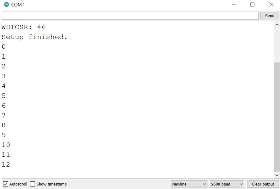
Once the code is uploaded to Arduino, open your serial monitor and set its baud rate.
You may also like to read:
- Arduino Comparator Tutorial with Example
- Send Sensor Readings to Android Phone using Arduino and NRF24L01 via BLE
- I2C LCD interfacing with Arduino Display Scrolling Text and Custom Characters
- Control 28BYJ-48 Stepper Motor with ULN2003 Motor Driver and Arduino
- RS485 Serial Communication between two Arduino boards
- Interface nRF24L01+ Wireless Module with Arduino
- DRV8825 Driver Module for Stepper Motor with Arduino