In this tutorial, we will learn how to send sensor readings to an Android phone using Arduino nRF24L01+ module, and BLE. The transfer of data will be through Bluetooth Low Energy (BLE). We will use DHT22 sensor to access current temperature readings and send them to our android phone using nRF24L01+ RF module that we will use as a BLE module with Arduino.
For this guide, we will require the followings components.
Hardware
- Arduino UNO
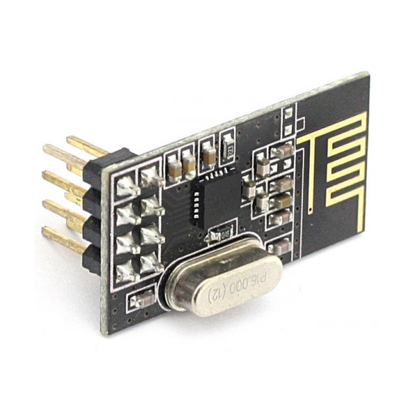
- nRF24L01/nRF24L01+ module
- DHT22 sensor
- Connecting Wires
Software
- Arduino IDE
- nRF Connect for Mobile by Nordic SemiConductor
What is Bluetooth Low Energy?
Bluetooth Low Energy is a wireless personal area network technology designed by the Bluetooth Special Interest Group; consisting of 150 companies. Following Bluetooth 4.x, the corresponding Mesh Model specification for Bluetooth 5 was released in 2017. It effectively quadrupled the range by using increased transmit power and coded physical layer; doubled the speed by using optical half of the symbol time compared to Bluetooth 4.x; and provided an eight-fold increase in data broadcasting capacity by increasing the advertising data length of Bluetooth Low Energy transmissions. Compared to Classic Bluetooth, Bluetooth Low Energy was intended to provide considerably reduced power consumption and cost; while maintaining a similar communication range.
![Figure 1 Bluetooth Low Energy Gateway solution [8]](http://microcontrollerslab.com/wp-content/uploads/2019/09/Figure-1-Bluetooth-Low-Energy-Gateway-solution-8.png)
Recommended Reading: Introduction to Bluetooth Low Energy
nRF24L01 as BLE Module
nRF24L01 is one of the legal RF communicators for modern applications. It is the cheapest one and it comes with great features. A single module communicates at 2.4 GHz frequency which makes it legal. It can transmit and receive data by a single module. Trans receiving is not its only ability, it can communicate with a total of 6 other same NRF24L01 modules at a single time. The device interfaces with the Arduino application and covers all kinds of remote-control applications. This wireless module uses SPI communication protocol and offers a 10MBs data rate with a 125 address range which makes it reliable the most reliable RF module. The RF module uses the GFSK module to transceiver the data.
In this guide, we will use this RF module to act as a BLE module with Arduino UNO to send data over to other Bluetooth devices in our case an android phone. The nRFL01 module’s channel frequencies variate from 2400MHz to 2525MHz that consist of 40 channels. Inclusive of these 40 channels, we have three channels for Advertising. These are information packets that are used by other Bluetooth devices to connect to.
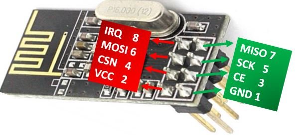
nRF24L01+ Module Pinout
In nRF24L01+ there aren’t any special pins, all pins it offers to communicate are present in all microcontrollers and boards. The device will interface with an external microcontroller/Arduino through these pins to operate. It consists of 8 pins. All available pins are:
| Pin Number | Name | Description |
|---|---|---|
| 1 | GND | nRF24L01+ operates with another microcontroller and it will need a common ground to operate with it. GND pin will solve the requirement of the common ground. |
| 2 | VCC | The power pin of the module is VCC (1.9-3.9V), which connects itself with the power supply. |
| 3 | CE | CE is the Chip Enable pin. It activates the transmission/receiving of the module. It will only activate the device when there is a HIGH state on itself. |
| 4 | CSN | This pin (Chip Select Not) is for activating the data listening and processing from the microcontroller. To keep the data communication between the microcontroller and the module it should be HIGH. |
| 5 | SCK | It is the clock pulse pin of SPI communication in nRF24L01+. The data will move between the module and the microcontroller according to the clock pulse on the SCK pin. |
| 6 | MOSI | Master Out Slave In pin, SPI input pin. |
| 7 | MISO | Master In Slave Out pin, SPI output pin. |
| 8 | IRQ | IRQ is an interrupt pin, which generates the event whenever new data is available for SPI pins. It helps to send feedback to the transmitter. |
For more information regarding this RF module refer to the following articles:
Interfacing Arduino with nRF240L01+ and DHT22 sensor
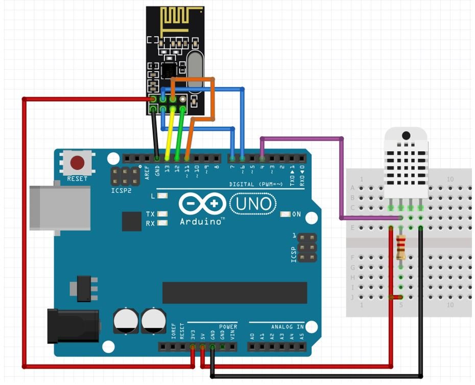
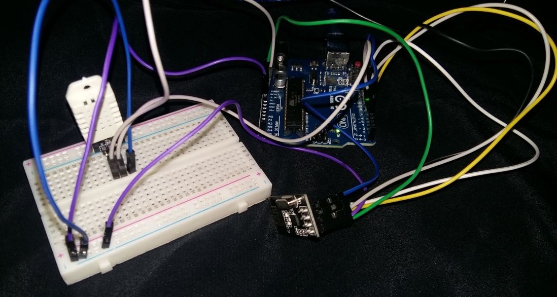
Follow the schematic diagram below to connect the three devices properly.
Arduino UNO with nRF24L01+
We have used the default SPI pins of Arduino UNO to connect with the SPI pins of the transceiver module. The diagram below shows the default SPI pins of Arduino UNO.
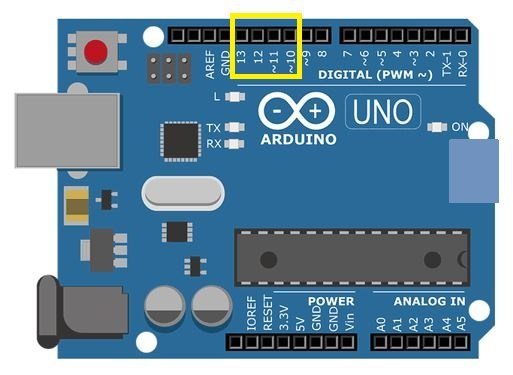
- Pin11 = MOSI
- Pin12 = MISO
- Pin13 = SCK
- Pin10 = SS
We have connected the SPI pins MOSI, MISO, and SCK of nRF24L01+ module with the respective SPI pins of Arduino UNO i.e. digital pin 11, pin 12, and pin 13 respectively. VCC pin and GND pin are connected with 3.3V and GND from Arduino respectively. Moreover, connect CE and CSN with any appropriate digital pin of the Arduino board. We have used digital pin 7 to connect with CE and digital pin 6 to connect with CSN.
Arduino UNO with DHT22 Sensor
Connect the DHT22 to Arduino along with a 10K ohm pull-up resistor.
- The first pin is a power supply (VCC) pin. Connect it with the 5 V pin of Arduino.
Data out is the pin through which we get temperature and humidity samples from the DHT sensor. Connect this pin with digital pin 4 of Arduino and also connect the data pin with a 10k pull-up resistor. But you can also use any digital pin of Arduino as well.
A Pull-up resistor is used to keep the data pin high for proper communication between the microcontroller and sensor. - Third pin is not used.
- Connect the fourth pin (GND) to the ground pin of the Arduino board
If using a DHT22 sensor module instead then no need to add the pull-up resistor.
Installing Libraries
We will require the following libraries for this project:
RF24 Library
We will require the RF24 library to program our Arduino board with nRF24L01+ in Arduino IDE easily. This library provides us with adequate functions that unable a smooth and easy communication between devices.
This library is not available in the Arduino library manager so we will have to download and load it in the IDE ourselves. We will use GitHub to download the library and then place it in the library folder of our Arduino IDE.
Click RF24 library to open the respective GitHub page for the library.

Click the Code button and go to the Download Zip option as highlighted in the figure. Your zip file will get downloaded to your computer right away. After the download is complete, extract the .zip file to the Arduino library folder.
You can also go to Sketch > Include Library > Add .zip Library inside the IDE to add the library as well. Through this procedure now we will be able to use the functionalities of the library inside our Arduino IDE.
BTLE library
To use BLE functionality, we will require the BTLE library available at GitHub. This Arduino library is for basic BLE with nRFL201+ module.
Click BTLE library to open the respective GitHub page for the library.

DHT Libraries
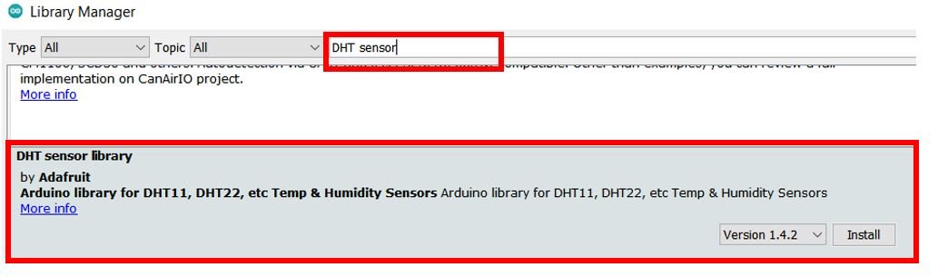
We have an Arduino library for DHT sensors which can be easily used to get values of temperature only by calling a single line of function. This library is provided by Adafruit and is available in Arduino Library Manager.
Open your Arduino IDE. Go to Sketch > Include Library > Manage Libraries. Type ‘DHT sensor’ and press enter. Install the library shown below:
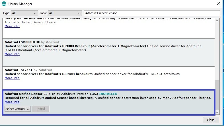
We also need to install the Adafruit Unified Sensor library. To install this, type ‘Adafruit Unified Sensor’ in the search bar and press enter. Install the library shown below:
After installing all the libraries, restart your IDE.
Arduino Sketch BLE Communication between Arduino and Android Phone using nRFL201 module
Open your Arduino IDE and go to File > New. A new file will open. Copy the code given below in that file and save it.
#include <SPI.h>
#include <RF24.h>
#include <BTLE.h>
#include <DHT.h>

#define DHTPIN 4
#define DHTTYPE DHT22
DHT dht(DHTPIN, DHTTYPE);

RF24 radio(7,6); // CE, CSN
BTLE btle(&radio);

void setup() {
  Serial.begin(115200);
  delay(1000);
  Serial.print("BLE and DHT Starting... ");
  Serial.println("Send Temperature Data over BTLE");
  dht.begin();
  btle.begin("My DHT");    // 8 chars max
  Serial.println("Successfully Started");
}

void loop() {
  float temp = dht.readTemperature();
  if (isnan(temp)) {
    Serial.println(F("Failed to read from DHT sensor!"));
    return;
  }
  Serial.print(" Temperature: ");
  Serial.print(temp);
  Serial.println("°C ");

  nrf_service_data buf;
  buf.service_uuid = NRF_TEMPERATURE_SERVICE_UUID;
  buf.value = BTLE::to_nRF_Float(temp);

  if (!btle.advertise(0x16, &buf, sizeof(buf))) {
    Serial.println("BTLE advertisement failed..!");
  }
  btle.hopChannel();
  delay(2000);
}
How the Code Works?
The code starts off by including all the libraries which are necessary for the BLE communication project. We have included all the libraries that we previously installed. These include libraries for RF, DHT, SPI communication and BLE functionalities.
#include <SPI.h>
#include <RF24.h>
#include <BTLE.h>
#include <DHT.h>
The following lines of code will specify the type of DHT sensor and the GPIO pin of the Arduino UNO board which we will connect with the data pin of the sensor. We are using digital pin 4 that will be connected with the data pin of the DHT sensor. You can use any appropriate digital pin as well.
#define DHTPIN 4
#define DHTTYPE DHT22
DHT dht(DHTPIN, DHTTYPE);
Next, we will create an object of RF24 called radio() and pass the Arduino digital pins we have connected with CE and CSN pins of nRF24L01 module as parameters inside it. The number 7 represents the CE pin and 6 represents the CSN pin. Both are changeable according to any digital pins. Here they are according to the circuit we used above.
RF24 radio(7,6); // CE, CSNThen we will create an object of BTLE called btl() and pass &radio as an argument inside it.
BTLE btle(&radio);Inside the setup() function, we will open the serial communication at a baud rate of 115200. Then, we will initiate the connection with the DHT sensor as well by using the begin() method on the dht object. Moreover, we will also initiate BTLE by using the begin() method on the btle object and pass the name of the Bluetooth as a parameter inside it. Here we have named ours ‘My DHT’. You can use any name but make sure it does not go over eight characters.
void setup() {
  Serial.begin(115200);
  delay(1000);
  Serial.print("BLE and DHT Starting... ");
  Serial.println("Send Temperature Data over BTLE");
  dht.begin();
  btle.begin("My DHT");    // maximum 8 characters
  Serial.println("Successfully Started");
}
loop()
Inside the loop() function, we will first acquire the current temperature from the DHT sensor and store it in the floating variable ‘temp.’
float temp = dht.readTemperature(); Moreover, we will check if the connection between the Arduino and the DHT sensor is correct or not or the value is being accessed properly or not. This is done through an if() statement. If the reading is not proper then an error message will be printed. This will help us in debugging our circuit or a possible issue in the initialization of the sensor.
 if (isnan(temp)) {
    Serial.println(F("Failed to read from DHT sensor!"));
    return;
  }
The temperature readings will be printed in the serial monitor along with its unit.
 Serial.print(" Temperature: ");
  Serial.print(temp);
  Serial.println("°C ");
Next we will save the temperature reading and send it over to the BLE module. The BLE module will advertise the temperature reading which will then be received by the android phone in its app. We are adding a delay of 2 seconds between every reading.
  nrf_service_data buf;
  buf.service_uuid = NRF_TEMPERATURE_SERVICE_UUID;
  buf.value = BTLE::to_nRF_Float(temp);

  if (!btle.advertise(0x16, &buf, sizeof(buf))) {
    Serial.println("BTLE advertisement failed..!");
  }
  btle.hopChannel();
  delay(2000);
Demonstrating Arduino BLE Communication with an Android App
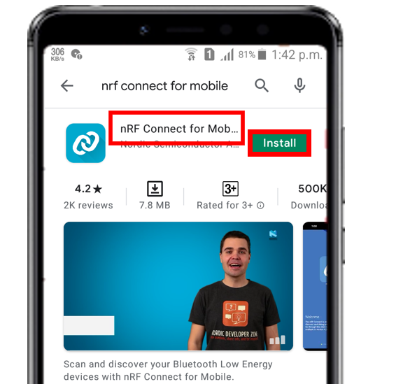
To perform the demonstration of this project, we will need a phone which supports BLE connection. After you have got your hands on one, open the Play Store and search for ‘nRF Connect for Mobile.’ This is a free app that will help us to check for the connection. Install the app on your cell phone.
Before proceeding further, make sure to change your Bluetooth settings by enabling the Bluetooth adapter in your cell phone as shown in the figure.

Upload the code to Arduino. But, before uploading code, make sure to select the Arduino board from Tools > Board and also select the correct COM port to which the Arduino board is connected from Tools > Port.

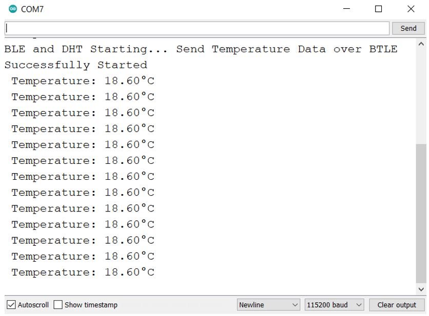
Once the code is uploaded to Arduino, open the serial monitor and set the baud rate to 115200. Both the DHT sensor and BTLE will initialize. The temperature readings will start appearing in the Serial Monitor.
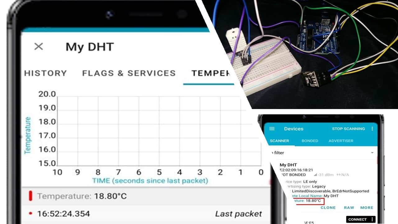
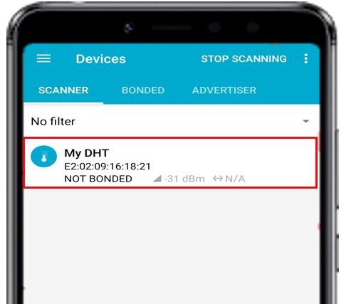
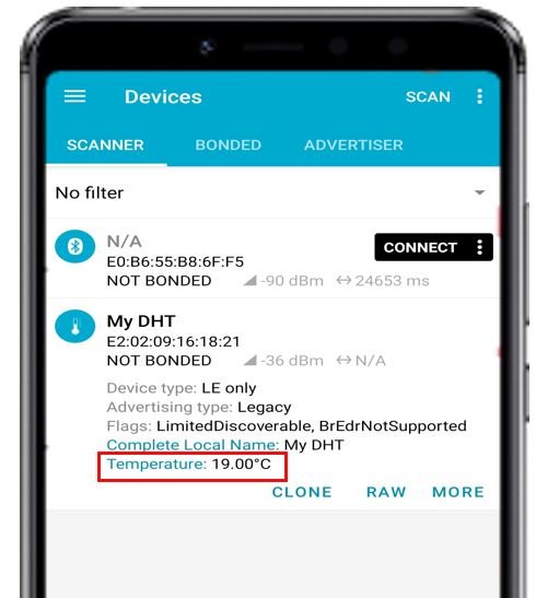
Now, open the nRF Connect for Mobile application and tap the Scan button. This will scan for all the devices which are close to the cell phone. Thus, our nRF24L01 connected with Arduino will also get scanned and you will be able to see ‘My DHT’ written among the scanned devices as shown below:
Click on it and you will be able to view the current temperature reading in degree Celsius.
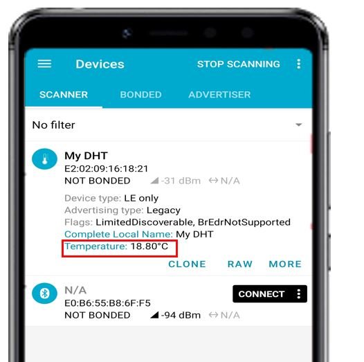
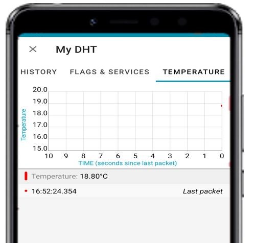
Now click ‘MORE’ and head over to ‘TEMPERATURE.’ Here you will be able to view the temperature reading and the time of the last packet sent.
Now refresh the page to view the current temperature reading again. Now it is 19.00 degree Celsius.
We were successfully able to show you how to send sensor data to an android phone with Arduino and nRFL01 using BLE.
You may also like to read:
Good explanation, but why didn’t you include Humidity in the transmitted data?
How would this sending of two different data sets be achieved?