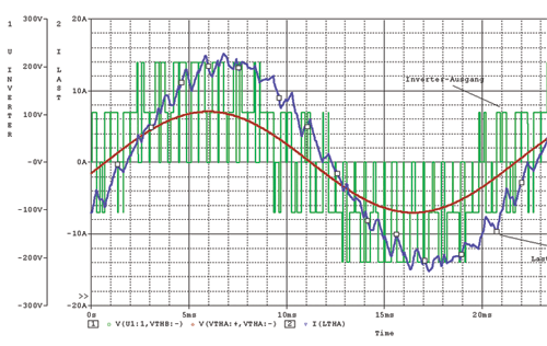
PSpice getting started tutorials for beginners. Starting from beginner’s level to advanced level tutorials. You will learn about this software starting from how to download and install it. How to design and simulate digital and electronic circuits in PSpice. These tutorials will help you get started with this software. It will be a step-by-step guide on Orcad simulation and schematic design software. PSpice tutorials are used in many engineering applications for simulation purposes. For example, it is used to simulate and design electronic circuits, digital circuits, and you will see examples of all of these in this complete list of tutorials.
If you are taking a digital electronics course in university and you want to check output or want to verify behavior of your electronics circuits, you can use this to simulate digital circuits like digital gates, decoders, multiplexers, full adder circuits and many others. Similarly, one can simulate analog circuit like amplifiers, oscillators with the software. So if you want to learn about this software, you should check complete guide at the end of article.
Introduction to PSpice software
In First tutorial, you will learn how to download and install this simulation and circuit design software with step by step guide. Here PSICE stands for simulation program for simulation circuits emphasis. It is a electronics circuit simulator. It is used to design and predict behavior of analog and digital electronics circuits. There are two types of versions exit for it.
- SPICE: It is used for personal computers.
- HSPICE: It is used for workstations or high-power computers.
Types of Analysis with PSpice
It has built in libraries for many electronics components like transistors, Gates, Flip Flops and many others. So you can easily simulate many electronics circuit by easily connecting these built in components with each other. You will learn about all these components in all tutorials given below. As you know, in electrical and electronics engineering, you always need a analysis of AC and DC circuits. So you can perform following types of analysis with the help of this software.
- Linear and Non linear AC circuit analysis
- Linear and Non linear DC circuit analysis
- Noise analysis of circuits
- sensitivity analysis of circuits
- Various types of electrical wave forms analysis
As I have mentioned earlier, this software has many built in components. Some of the main components are given below:
- AC voltage sources
- DC voltage sources
- Passive electronics components ( Resistors, capacitors, inductors , switches )
- Transistors
- MOSFETS
- Digital gates
File structure of simulation circuit
As you know for all type of software’s there exist a type of input format and a type of output format to a file used for this software. Input file for this circuit designing software is “.CIR”. When we press the simulation button .OUT file is generated and .BIN file is executed on the computer. It is not a case sensitive. you should give a unique name to each components. Components with duplicate will not let the simulation work. You should also assign a reference node to each circuit with respect to which you want to simulate the circuit. you need to create netlist again if you made any changes to circuit.
Complete list of PSpice tutorials
- Tutorial number one: Download and installation you will learn how to download and install it with step by step guide.
- Tutorial number two : Getting started with simulation software
- Tutorial number three: RL, RC and RLC circuits simulations in pspice
- Tutorial number four: Half wave and full wave rectifier simulation in Pspice
- Tutorial number five: DC circuits analysis in pspice
- Tutorial number six: AC circuits analysis in pspice
- Tutorial number seven: Inverting and non-inverting amplifier design and simulation using Pspice
- Tutorial number Eight : Buck converter design and simulation usign PSpice
- Tutorial number Nine: Low pass and high pass filter design using PSpice
- Tutorial number ten: Digital system simulation using PSpice
- Tutorial number eleven: How design and simulate Multiplexer in PSpice
- Tutorial number 12 : Digital D flip flop design using PSpice
- Tutorial number thirteen: Half adder and full adder with PSpice simulation software
- Tutorial number fourteen: High pass filter design using PSpice
- Tutorial number fifteen: Digital Encoder design and simulation PSpice
- Sub circuits : Sub circuits contains contains collections of electronics components which is used as a single components. For example operational amplifier consists of many transistors and other components. But you can use it as a single electronic component.
- EDIF : EDIF stands for Electronics Design Interchange Format. It is used to create netlists
Conclusion
In conclusion, PSpice is a powerful software tool that allows users to design, simulate, and analyze digital and electronic circuits. With a wide range of built-in components and analysis capabilities, it serves as an invaluable resource for engineers and students alike. From downloading and installing the software to diving into various tutorials, users can learn step-by-step how to harness the full potential of PSpice. Whether you’re interested in simulating digital gates, amplifiers, or even entire digital systems, PSpice offers a comprehensive platform for circuit design and analysis. With its user-friendly interface and extensive functionalities, PSpice continues to be a go-to software for engineers working in diverse engineering applications. Explore the complete list of tutorials and unlock the possibilities of PSpice to bring your circuit designs to life.


