In this tutorial, we will learn about HC-05 Bluetooth to serial port module and how to interface it with ESP8266 NodeMCU. This Bluetooth device operates on UART communication. In other words, it uses serial communication to transmit and receive data serially over standard Bluetooth radio frequency. Therefore, we will use TX, RX pins of ESP8266 to connect with the module.
In this tutorial, we will use an android application to communicate with the NodeMCU through the HC-05 Bluetooth module. We will see an example to control an LED from the Android application using Bluetooth wireless communication. The LED will be connected with a GPIO pin of the ESP8266 and in effect, we will be controlling that pin.
Prerequisites
We will use Arduino IDE to program our ESP8266 development boards. Thus, you should have the latest version of Arduino IDE. Additionally, you also need to install the ESP8266 plugin. If your IDE does not have the plugin installed you can visit the link below:
Installing ESP8266 library in Arduino IDE and upload code
Bluetooth Terminal Application
Throughout this guide, we will use an android smartphone that will connect to our ESP8266 development board. So, make sure you have an android phone at hand. We will also use a Bluetooth terminal application to pair the two devices together.
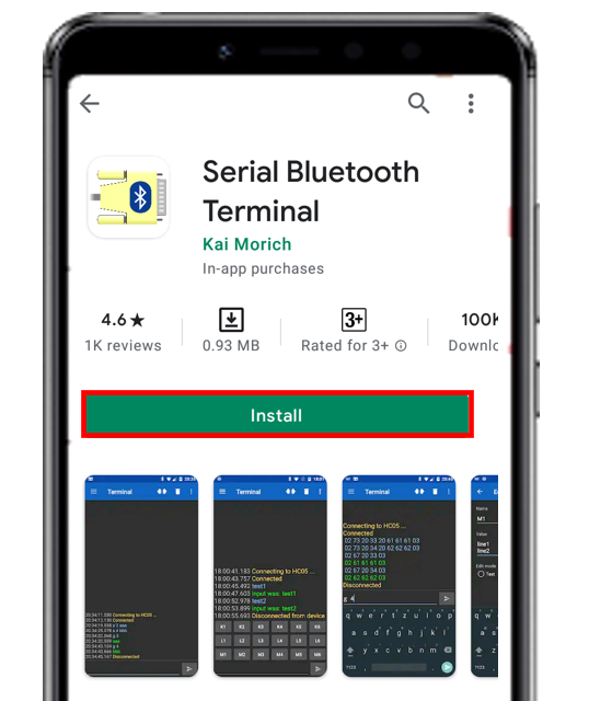
Go to the Play Store and download the application by the name: Serial Bluetooth terminal. This can be seen in the figure below.
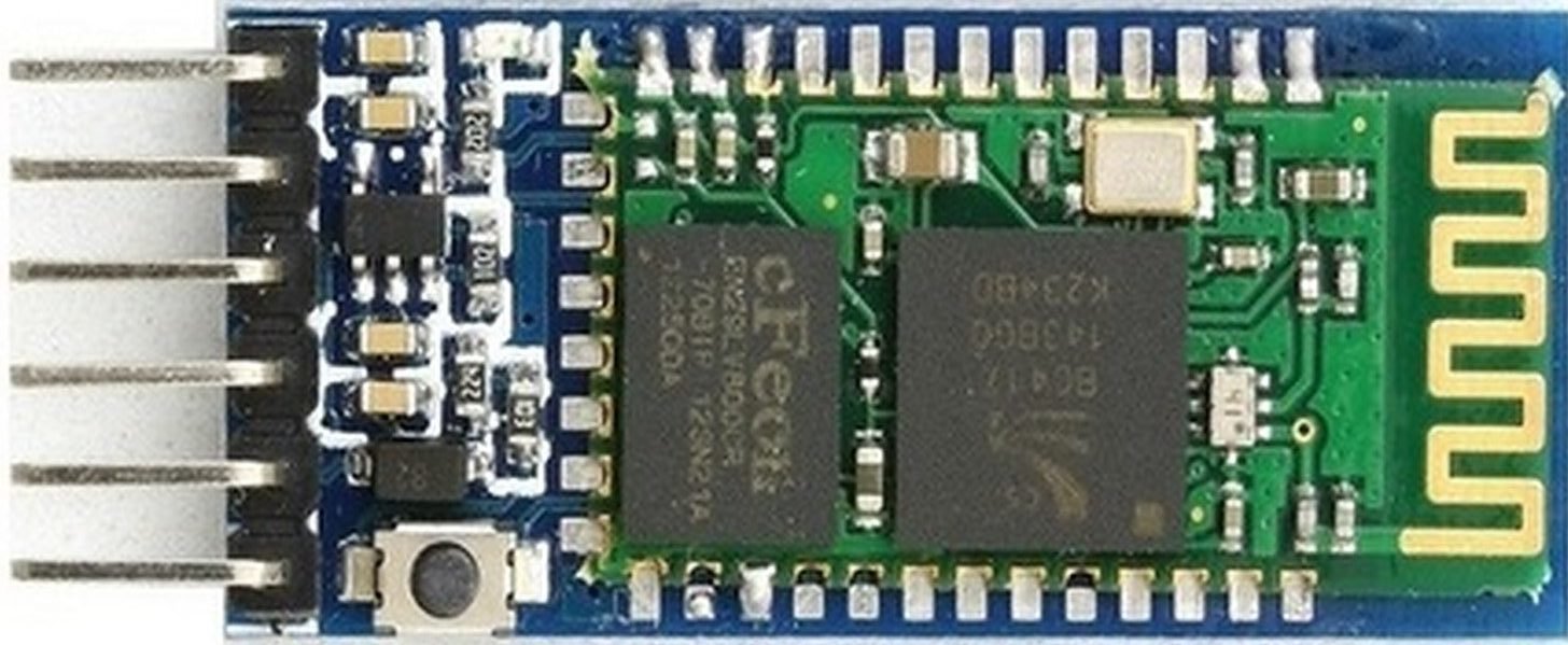
HC-05 Introduction
HC-05 is one of the commonly used Bluetooth device that uses a UART communication protocol. The HC-05 Bluetooth is much different in features from all other Bluetooth devices because of its multiple pins and their functions. It has multiple pins for the different method which makes it unique as compared to others. The module normally operates at UART serial communication with TX and RX pins at 9600 baud rates. However, it can be programmed with AT commands and it supports 9600,19200,38400,57600,115200,230400,460800 baud rates.
Its CSR Bluecore 04-External single chip is already configured to communicate with other Bluetooth devices through serial communication. It offers a two-way communication method and the HC-05 can act as either slave and master. The Bluetooth module offers only short distance communications due to its limitation but still, most of the devices come with it due to its speed and security. The limitation of this device is that it doesn’t allow to transfer any kind of media.
In short, this module can be used to perform low-cost wireless communication between microcontrollers such as Arduino, TM4C123, Pic Microcontroller, Raspberry Pi, BeagleBone, STM32, and Arduino Mega, etc. Also, we can use it for communication between a microcontroller and PC or Android application. There are many Android applications available in the Google Play store which we can use to send and receive data to/from HC05. For this tutorial, we will use ‘Serial Bluetooth Terminal’ application that we installed previously.
Recommended Reading: HC-05 Bluetooth Module
Pinout
The HC-05 comes with multiple pins and indicators, which helps to control different operations and view their states through indicators. This pinout diagram provides indications of all pins.
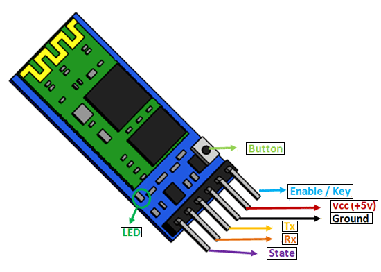
The table below also briefly describes the functionality of each pin.
| Pin | Description |
| VCC | The operating voltage range is 3.3 volts. But I/O pins can withstand voltage of up to 5 volts. Therefore, we can connect 5 volts power source to this pin, and also other pins can also operate on 5 volts signals such as Tx and Rx signals. |
| GND | Ground reference of both ESP8266 and HC-05 should be at the same level. Therefore, we should connect a power supply, HC05, and ESP8266 ground pins to each other. |
| Tx | As discussed earlier, the HC-05 Bluetooth module uses UART communication to transmit data. This is a transmitter pin. The TX pin will be the data transfer pin of the module in UART. |
| Rx | This pin is a data receiving the pin in UART communication. It is used to receive data from the microcontroller and transmits it through Bluetooth. |
| State | The state shows the current state of the Bluetooth. It gives feedback to the controller about the connectivity of Bluetooth with another device. This pin has an internal connection with the onboard LED which shows the working of HC05. |
| Enable/Key | Using an external signal, Enable/Key pin is used to change the HC-05 mode between data mode and command mode. The HIGH logic input will transfer the device in command mode and the LOW logic input will change the mode to data mode. By default, it works in data mode. |
| Button | The command and data mode states are changeable through a button present on the module. |
| LED | This pin shows the working status of module along with the State pin |
Interfacing HC-05 with ESP8266 NodeMCU
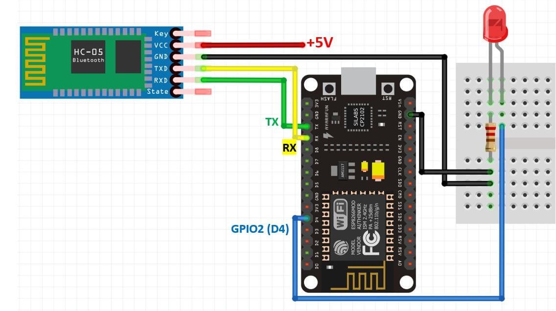
In this section, we will show you how to connect the HC-05 module with ESP8266. The connection of the HC-05 Bluetooth module with ESP8266 is very easy as we will be using the serial communication interface that consists of two pins TX and RX. As you know, in order to communicate with the HC-05 Bluetooth module, we need to use a UART communication port of the ESP8266 board. The figure below shows the RX and TX pins found on the ESP8266 board that consists of the UART interface.
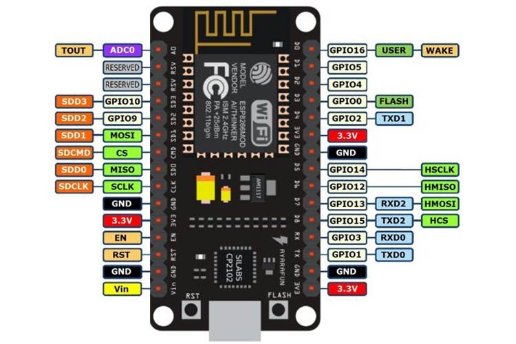
The HC-05 module has two serial input pins, both of which will be used for data communication. TX of HC-05 will be connected with RX of the ESP8266 and RX of HC-05 will be connected with TX of the ESP8266. The VCC pin of the HC-05 module will be connected with 5V power supply and the grounds will be common.
LED Control Example with HC-05 , ESP8266 and Android App
For demonstration purposes, we will control the ESP8266 GPIO pin with an LED connected to it. This will be done through the android application via the Bluetooth module. We will send ‘O’ or ‘X’ commands from our Serial Bluetooth Terminal application. Based on these commands, the LED will either turn ON or OFF.
We will require the following components for this project.
Required Components:
- ESP8266 NodeMCU
- HC-05 Bluetooth Module
- 5mm LED
- 220-ohm resistor
- Connecting Wires
- Breadboard
Schematic ESP8266 and HC-05
Follow the schematic diagram below to connect all the devices together. We will power the HC-05 module with a 5V power supply. The RX and TX pins of the HC-05 module will be connected with the TX and RX pins of the ESP8266 NodeMCU board respectively. We will use GPIO2 (D4) to connect with the anode pin of LED, and the cathode pin with the common ground through the 220-ohm resistor. Moreover, all the grounds will be in common.
The data will be transferred at the default baud rate of 9600 but it can also be changed.
Arduino Sketch: ESP8266 LED Control with HC-05 and Android App
Open your Arduino IDE and go to File > New. A new file will open. Copy the code given below in that file and save it.
int led_pin = 2;

void setup() {
 pinMode(led_pin, OUTPUT);
 Serial.begin(9600);
}

void loop() {

 if (Serial.available())
    {
      char data_received;
      data_received = Serial.read();
      if (data_received == 'O')
      {
       digitalWrite(led_pin, HIGH);
       Serial.write("LED is now ON!\n");
      }
      else if (data_received == 'X')
      {
       digitalWrite(led_pin, LOW);
       Serial.write("LED is now OFF!\n");
      }
      else
      {
       Serial.write("Specify correct option\n");
      }
    }
}
How the Code Works?
Firstly, we will define the ESP8266 GPIO pin that we will connect with the LED. It is GPIO2 (D4) in our case. You can use any appropriate output pin.
int led_pin = 2;Next, in the setup() function we will configure the led pin as an output through pinMode() function and pass the GPIO pin as the first parameter and OUTPUT as the second parameter inside it. Additionally, we will start the serial communication with the default baud rate of 9600.
void setup() {
 pinMode(led_pin, OUTPUT);
 Serial.begin(9600);
}
Inside the void loop() function we will first check if there is any data being received through the serial port. If there is any data it will get saved in the char variable ‘data_received.’ This will be achieved by using Serial.read().
char data_received;
data_received = Serial.read();
Then we will use if-else-if statement to check whether the character received is an ‘O’ or a ‘X’.
If we send the character ‘O’ from the Android app to HC-05 the red LED will turn ON and the onboard LED which is also connected with GPIO2 will turn OFF.
For ESP8266, the on-board LED works on an opposite logic as compared to other microcontrollers. To turn the onboard LED ON, a low signal is sent and to turn it OFF, a high signal is sent.
Similarly, if we transmit ‘X’ from the Android app to HC-05, the red LED will turn OFF and the onboard LED will turn ON.
If the character transmitted is not either one of these, then a message will be printed in the android application stating to specify the correct option.
 if (Serial.available())
    {
      char data_received;
      data_received = Serial.read();
      if (data_received == 'O')
      {
       digitalWrite(led_pin, HIGH);
       Serial.write("LED is now ON!\n");
      }
      else if (data_received == 'X')
      {
       digitalWrite(led_pin, LOW);
       Serial.write("LED is now OFF!\n");
      }
      else
      {
       Serial.write("Specify correct option\n");
      }
    }
Demonstration
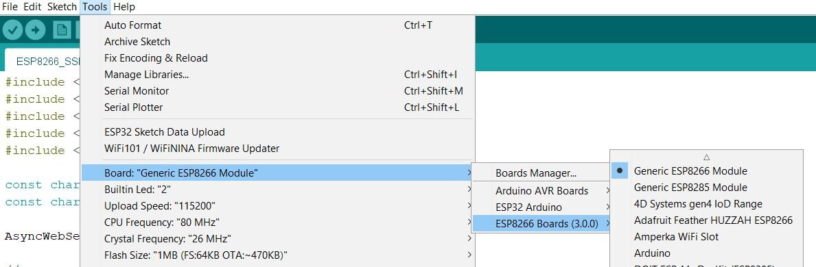
Choose the correct board and COM port before uploading your code to the board. Go to Tools > Board and select NodeMCU 1.0
Next, go to Tools > Port and select the appropriate port through which your board is connected.
Click on the upload button to upload the code into the ESP8266 development board.
After you have uploaded your code to the development board, press its RST button.

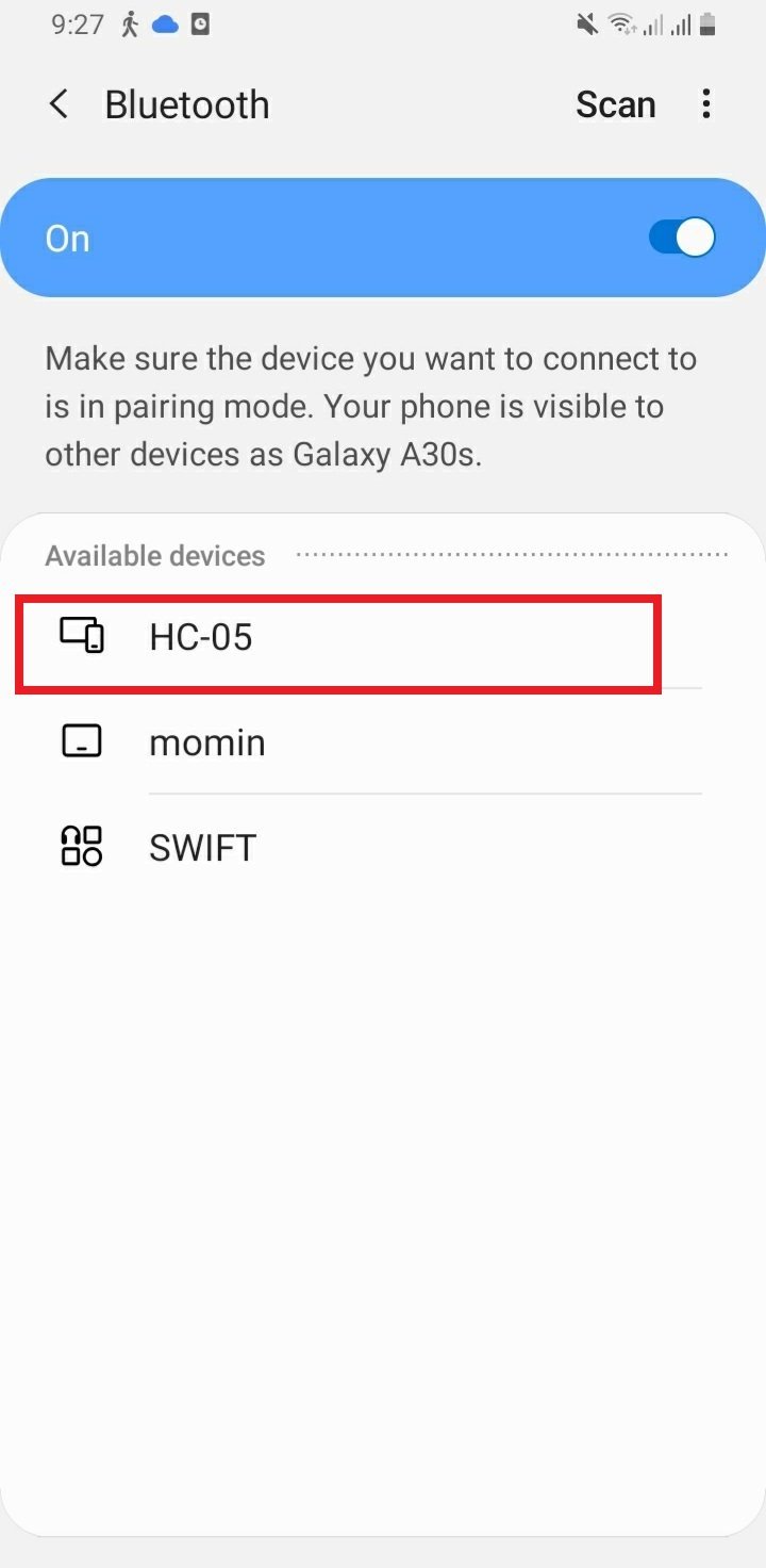
In your smartphone settings, enable Bluetooth and scan for available Bluetooth devices. You will see the HC-05 device in your scanned list. The default name for this Bluetooth device is “HC-05” and the default pin code is either “0000” or “1234”.
Setting up Android App
We will use an android smartphone to connect with our ESP8266 module. To do that you will have to perform a series of steps.
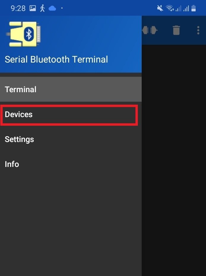
After you have installed the ‘Serial Bluetooth Terminal app, open it. On the top left corner of the screen, you will find three horizontal bars. Tap it.
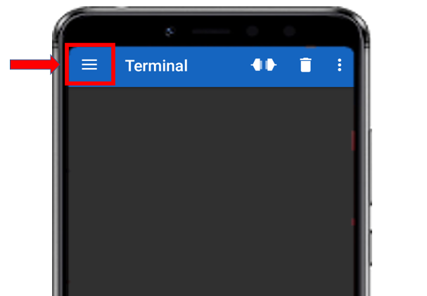
Now, tap on the Devices tab.
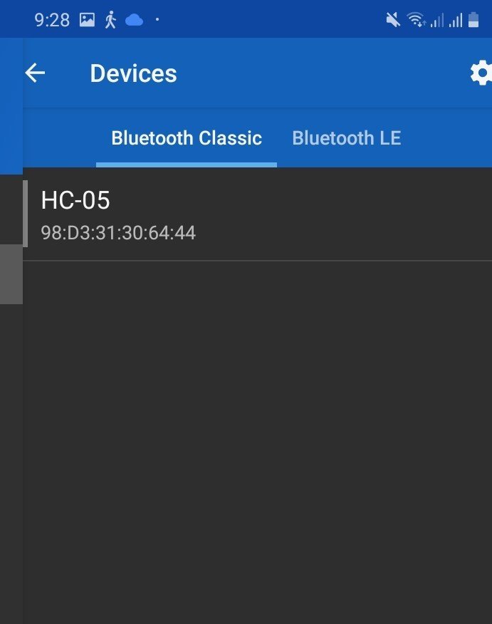
In the ‘available devices’ section, select ‘HC-05’
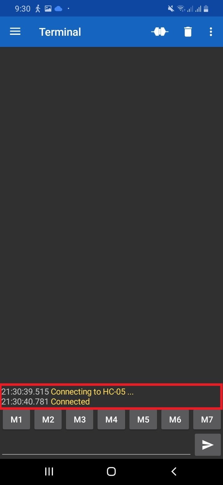
After you have selected the HC-05 module then tap the ‘link’ icon at the top of the screen. At first, you will get the message: ‘Connecting to HC-05.’ After a successful connection, you will get the message: ‘Connected.’
Now Type ‘O’ and click on the send button, you will see the red LED will turn ON and the onboard LED will turn OFF. In response, the ESP8266 sends an acknowledgment message and you will get a “LED is now ON!” message on the Bluetooth terminal app.
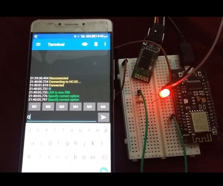
Similarly, if you send ‘X’ the red LED will turn OFF and the onboard LED will turn ON. You will get a “LED is now OFF!” response message from the ESP8266 board.
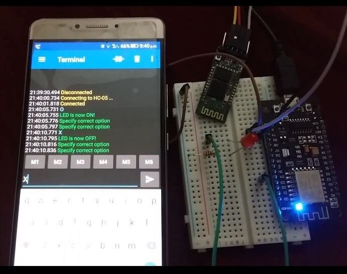
If you type anything other than that and press send then you will receive the response to specify the correct option.
Watch the video of the demo below:
Related Bluetooth tutorials and projects:
- HC06 Bluetooth Module Guide with Arduino Interfacing
- HC-05 Bluetooth Interfacing with TM4C123G Tiva C Launchpad – Keil uvision
- HM-10 Bluetooth Module – Interfacing Example with Arduino
- Introduction to Bluetooth Low Energy
- Control 2 DC Motors via Bluetooth and Arduino
- Bluetooth Based Home Automation
- Bluetooth based dc motor speed and direction control using Arduino
- HC-05 Bluetooth module interfacing with Arduino
- Bluetooth module HC 05 interfacing with pic microcontroller
- Bluetooth Controlled Robot using pic microcontroller