In this tutorial, we will learn how to interface I2C LCD with Raspberry Pi Pico and how to display simple text/numbers and custom characters on I2C LCD. This I2C LCD is a 16×2 device which means it can display 16 columns by two rows of characters. The characters are alphanumeric, but you can create custom characters for basic graphics, bar graphs, and similar visual elements. The LCD uses the standard HD44780 controller, and it also has an I2C circuit connected to it, which makes it easy to connect to the Pi Pico board. A standard 16×2 LCD without an I2C circuit has sixteen pins, making wiring complex and consuming many GPIO pins.
You can find more information about the pins by going to this article: 16×2 Liquid Crystal Display
If we connect a standard 16×2 LCD directly to the Raspberry Pi Pico, we need at least eight GPIO pins, which is inefficient for most projects. The better solution is to use an I2C LCD. In this tutorial, we use a 16×2 I2C LCD, but any LCD size will work the same way. The key advantage of using an I2C LCD is that we only need four pins (including the two power pins) to connect it to the Raspberry Pi Pico.
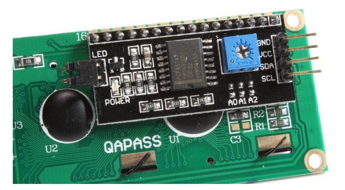
At the back of this liquid crystal display, you will also find a variable resistor (potentiometer). This potentiometer is used to adjust the contrast of the LCD display. It is very useful when operating the display in different ambient light conditions.
I2C LCD Key Specifications
Before connecting the I2C LCD to the Raspberry Pi Pico, it is helpful to understand the key specifications of this module. The I2C LCD module combines a standard HD44780-based LCD with a PCF8574 I/O expander chip that handles the I2C communication.
- Display type: 16 columns × 2 rows (16×2), can support other sizes like 20×4
- Controller IC: HD44780 LCD driver with PCF8574 I2C expander
- Operating voltage: 5V (VCC), logic compatible with 3.3V systems via the I2C interface
- I2C address: Default 0x27 or 0x3F, configurable via solder pads A0, A1, A2
- I2C speed: Supports standard mode (100 kHz) and fast mode (400 kHz)
- Backlight: LED backlight, controllable via software
- Character size: Each character is 5×8 pixels, with up to 8 user-defined custom characters stored in CGRAM
- Interface: 4-wire I2C (VCC, GND, SDA, SCL)
The PCF8574 chip on the back of the LCD communicates over the I2C bus and converts the serial I2C data into parallel signals required by the HD44780 controller. This is what reduces the required GPIO pins from 8–10 down to just 2 (SDA and SCL).
Prerequisites
Before starting this tutorial, make sure you are familiar with MicroPython and have it installed on your Raspberry Pi Pico. You should also have a working Integrated Development Environment (IDE). We will use Thonny IDE throughout this tutorial.
If you are using uPyCraft IDE, refer to this guide:
I2C LCD Pinout
The I2C LCD module exposes four pins for external connection:
- GND – Connect to the ground of the microcontroller
- VCC – Connect to 5V power supply (VBUS on Raspberry Pi Pico)
- SDA – I2C data line, connect to an SDA-capable GPIO pin
- SCL – I2C clock line, connect to an SCL-capable GPIO pin
The onboard PCF8574 expander handles all internal communication between the I2C bus and the LCD’s parallel interface, so you do not need to worry about wiring any additional data pins.
Interfacing I2C LCD with Raspberry Pi Pico
The I2C LCD connects to the Raspberry Pi Pico using four pins: GND, VCC, SDA, and SCL.
Raspberry Pi Pico I2C Pins
Raspberry Pi Pico has two I2C controllers, both accessible through its GPIO pins. The table below shows which GPIO pins are associated with each I2C controller. You must configure in your MicroPython code which GPIO pins correspond to your chosen I2C controller.
| I2C Controller | GPIO Pins |
| I2C0 – SDA | GP0/GP4/GP8/GP12/GP16/GP20 |
| I2C0 – SCL | GP1/GP5/GP9/GP13/GP17/GP21 |
| I2C1 – SDA | GP2/GP6/GP10/GP14/GP18/GP26 |
| I2C1 – SCL | GP3/GP7/GP11/GP15/GP19/GP27 |
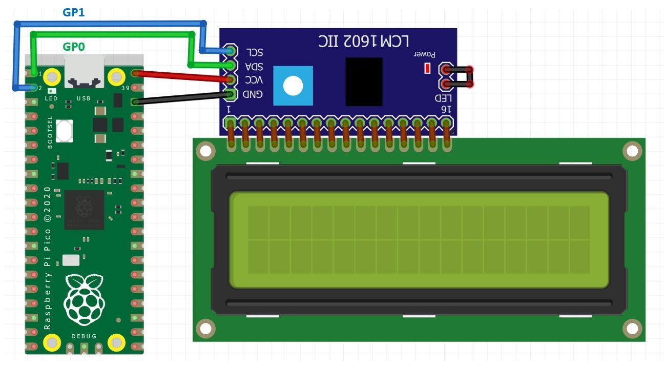
The connections used in this tutorial are shown below:
| I2C LCD | Raspberry Pi Pico |
| VCC | VBUS (5V from microUSB bus) |
| SDA | GP0 (I2C0 SDA) |
| SCL | GP1 (I2C0 SCL) |
| GND | GND |
The VCC pin is connected to the VBUS pin of the Raspberry Pi Pico, which provides 5V from the USB bus. Both grounds are connected together. The SCL pin of the I2C LCD connects to the I2C0 SCL pin of the Pi Pico, and the SDA pin connects to the I2C0 SDA pin. You can use other valid SDA/SCL pin combinations depending on your project layout.
Getting I2C LCD Address
Every I2C device has a unique address. For most I2C LCD modules, the default address is 0x27. However, it can also be 0x3F depending on the PCF8574 variant used and the state of the address selection pads (A0, A1, A2) on the back of the module. If all three pads are open (unsoldered), the address is typically 0x27. Bridging any of these pads changes the address.
Use the following I2C scanner code to confirm the address of your LCD before proceeding:
import machine

sdaPIN=machine.Pin(0)
sclPIN=machine.Pin(1)
i2c=machine.I2C(0,sda=sdaPIN, scl=sclPIN, freq=400000)

devices = i2c.scan()
if len(devices) == 0:
    print("No i2c device !")
else:
    print('i2c devices found:',len(devices))
for device in devices:
    print("At address: ",hex(device))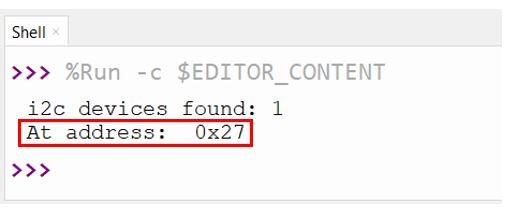
In the Thonny shell, the output will display the detected I2C address. In most cases, this will be 0x27. Make sure to use the address your scanner reports in all subsequent code examples.
I2C LCD MicroPython Libraries
This project requires two MicroPython library files: lcd_api.py and i2c_lcd.py. These libraries abstract the low-level I2C communication and provide easy-to-use methods for controlling the LCD.
To install these libraries, open a new file in Thonny, paste the contents of each library file, and save it to the Raspberry Pi Pico filesystem. Save the first file as lcd_api.py and the second as i2c_lcd.py. It is recommended to place them inside a lib folder on the Pico for better project organization. Make sure both files are saved to the Raspberry Pi Pico device (not your local PC) by selecting MicroPython device when Thonny asks where to save.
The lcd_api.py file defines the core LcdApi class that handles common LCD operations like putting strings, clearing the display, and managing custom characters. The i2c_lcd.py file extends LcdApi specifically for I2C-connected displays and manages the bit-banging needed to communicate via the PCF8574 expander. Together, these two files provide all the functionality needed for this tutorial.
Displaying Text/Numbers on I2C LCD using Raspberry Pi Pico
In this section, we will display a text message and count numbers on the LCD screen.
import machine
from machine import I2C
from lcd_api import LcdApi
from i2c_lcd import I2cLcd
from time import sleep

I2C_ADDR = 0x27
totalRows = 2
totalColumns = 16

i2c = I2C(0, sda=machine.Pin(0), scl=machine.Pin(1), freq=400000)
lcd = I2cLcd(i2c, I2C_ADDR, totalRows, totalColumns)

while True:
    lcd.putstr("Lets Count 0-10!")
    sleep(2)
    lcd.clear()
    for i in range(10):
        lcd.putstr(str(i))
        sleep(1)
        lcd.clear()
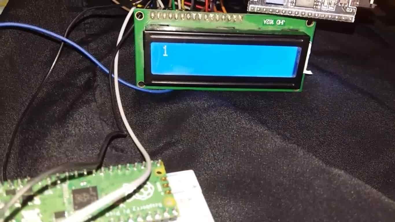
This program first displays the message “Lets Count 0-10!” for two seconds, clears the screen, then counts from 0 to 9 with a one-second pause between each number.
How the Code Works?
Let us walk through the code step by step.
First, we import all the required modules. The I2C class from the machine module handles the I2C hardware. The sleep function from time provides delays. LcdApi and I2cLcd come from the libraries we uploaded to the Pico.
import machine
from machine import I2C
from lcd_api import LcdApi
from i2c_lcd import I2cLcd
from time import sleep
Next, we define the I2C address and screen dimensions. The I2C_ADDR is the address reported by the scanner code above. The totalRows and totalColumns define the screen size — change these if you are using a 20×4 display instead of a 16×2.
I2C_ADDR = 0x27
totalRows = 2
totalColumns = 16
i2c object
We initialize the I2C peripheral by creating an I2C object. The first parameter (0) selects the I2C0 controller. The sda and scl parameters specify the GPIO pins used for the data and clock lines. The freq parameter sets the I2C bus speed to 400 kHz (fast mode), which improves display responsiveness.
i2c = I2C(0, sda=machine.Pin(0), scl=machine.Pin(1), freq=400000)lcd object
The I2cLcd object ties together the I2C bus, the device address, and the display dimensions. This object provides all the methods we use to interact with the LCD, such as putstr(), clear(), and custom_char().
lcd = I2cLcd(i2c, I2C_ADDR, totalRows, totalColumns)Display Text/Numbers
Inside the infinite loop, we call lcd.putstr() to write a string to the screen starting from the current cursor position (top-left by default). After displaying the text for 2 seconds, lcd.clear() erases everything and returns the cursor to the home position. The for loop then counts from 0 to 9, converting each integer to a string before passing it to putstr().
while True:
    lcd.putstr("Lets Count 0-10!")
    sleep(2)
    lcd.clear()
    for i in range(10):
        lcd.putstr(str(i))
        sleep(1)
        lcd.clear()
Demonstration
Upload the main.py file to your Raspberry Pi Pico. Once uploaded, adjust the contrast potentiometer on the back of the LCD until the characters become clearly visible on the screen.
Display Custom Characters on I2C LCD using Raspberry Pi Pico
In this section, we will display custom characters on the LCD screen.
Each character block on the 16×2 LCD consists of a 5×8 pixel grid. You can define up to 8 custom characters at a time by storing their pixel patterns in the LCD’s CGRAM (Character Generator RAM). These custom characters are defined using a bytearray of 8 bytes, where each byte represents one row of the 5×8 grid.
The easiest way to create the bytearray for a custom character is to use an online LCD character generator. Visit the LCD Custom Character Generator and design your character by clicking the pixel grid.
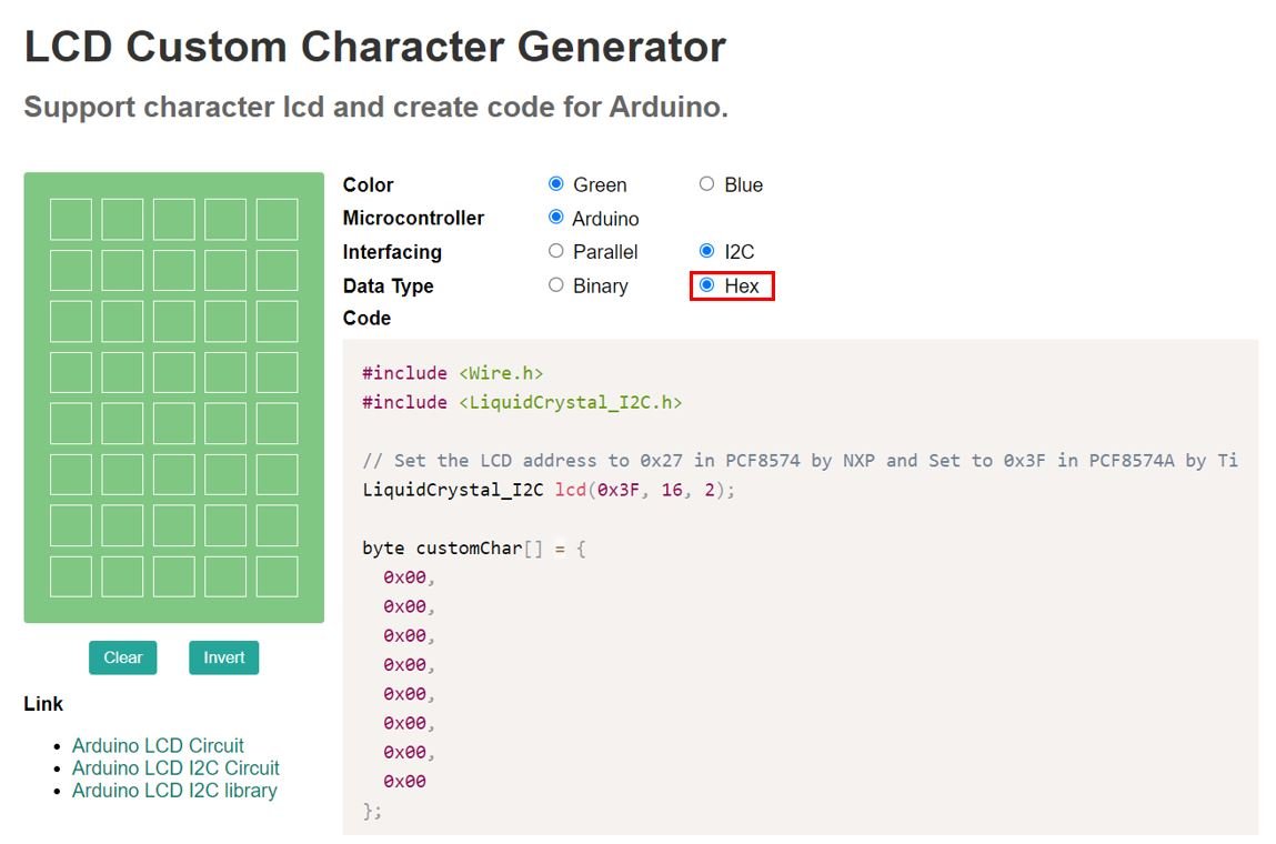
Select the data type as ‘Hex’ in the generator. Click the pixels in the 5×8 block to toggle them on or off, and the corresponding hex byte values will be generated automatically. Copy these hex values and place them inside your bytearray in the MicroPython code.
In our example, we will create a heart character and a smiley face. The hex data for each character is shown highlighted in the generator tool.
Once you have the hex values, paste them into your bytearray. You can define up to 8 different custom characters, stored at positions 0 through 7 in the LCD’s CGRAM.
MicroPython Display Custom Character on I2C LCD
import machine
from machine import I2C
from lcd_api import LcdApi
from i2c_lcd import I2cLcd
I2C_ADDR = 0x27
totalRows = 2
totalColumns = 16
i2c = I2C(0, sda=machine.Pin(0), scl=machine.Pin(1), freq=400000)
lcd = I2cLcd(i2c, I2C_ADDR, totalRows, totalColumns)
heart = bytearray([0x00,0x00,0x1B,0x1F,0x1F,0x0E,0x04,0x00])
face = bytearray([0x00,0x00,0x0A,0x00,0x11,0x0E,0x00,0x00])
lcd.custom_char(0, heart)
lcd.custom_char(1, face)
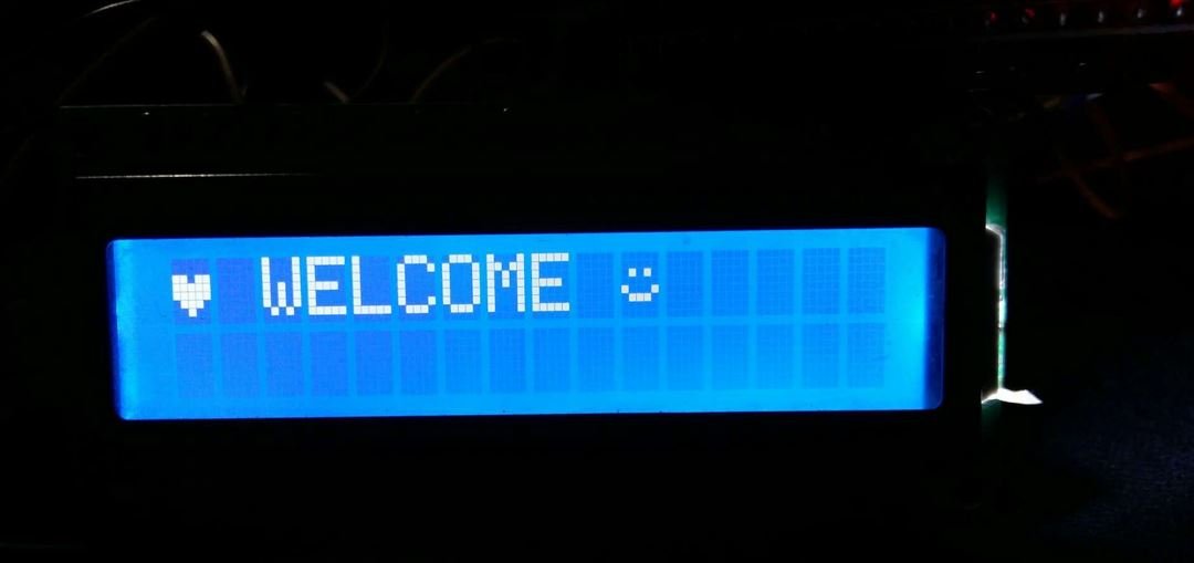
lcd.putstr(chr(0)+" WELCOME "+chr(1))This code displays the word ‘WELCOME’ flanked by a heart symbol on the left and a smiley face on the right.
How the Code Works?
The setup code (importing modules, creating the I2C and LCD objects) is the same as the previous example. The additional steps relate to defining and displaying custom characters.
First, we define bytearrays for the heart and smiley face using hex values obtained from the LCD Custom Character Generator:
heart = bytearray([0x00,0x00,0x1B,0x1F,0x1F,0x0E,0x04,0x00])
face = bytearray([0x00,0x00,0x0A,0x00,0x11,0x0E,0x00,0x00])
Next, we register these custom characters in the LCD’s CGRAM. The first argument to lcd.custom_char() is the memory slot (0–7), and the second argument is the bytearray defining the pixel pattern:
lcd.custom_char(0, heart)
lcd.custom_char(1, face)
Finally, we display the custom characters using chr() with the slot number to reference them inline within the string. Slot 0 outputs the heart, and slot 1 outputs the smiley face:
lcd.putstr(chr(0)+" WELCOME "+chr(1))Useful I2C LCD Library Methods
The lcd_api.py and i2c_lcd.py libraries provide several useful methods for controlling the display. Here is a summary of the most commonly used ones:
- lcd.putstr(“text”) – Writes a string to the LCD starting at the current cursor position.
- lcd.clear() – Clears the display and moves the cursor back to position (0, 0).
- lcd.move_to(col, row) – Moves the cursor to a specific column and row (both zero-indexed).
- lcd.putchar(‘c’) – Writes a single character at the current cursor position.
- lcd.custom_char(location, bytearray) – Stores a custom character at the given CGRAM slot (0–7).
- lcd.backlight_on() / lcd.backlight_off() – Turns the LCD backlight on or off programmatically.
- lcd.display_on() / lcd.display_off() – Turns the entire display on or off without clearing it.
- lcd.blink_cursor_on() / lcd.blink_cursor_off() – Enables or disables a blinking block cursor.
Using lcd.move_to(col, row) is especially important when you want to display text on a specific line or column. For example, lcd.move_to(0, 1) moves the cursor to the beginning of the second row, allowing you to display different information on each line simultaneously.
Displaying Sensor Data on the LCD
One of the most practical uses for an I2C LCD with Raspberry Pi Pico is displaying real-time sensor readings. The following example demonstrates how to display data on two separate lines:
import machine
from machine import I2C
from lcd_api import LcdApi
from i2c_lcd import I2cLcd
from time import sleep

I2C_ADDR = 0x27
totalRows = 2
totalColumns = 16

i2c = I2C(0, sda=machine.Pin(0), scl=machine.Pin(1), freq=400000)
lcd = I2cLcd(i2c, I2C_ADDR, totalRows, totalColumns)

# Simulated sensor value (replace with actual sensor reading)
sensor_value = 23.5

while True:
    lcd.clear()
    lcd.move_to(0, 0)  # First row
    lcd.putstr("Temp Sensor")
    lcd.move_to(0, 1)  # Second row
    lcd.putstr("Temp: " + str(sensor_value) + " C")
    sleep(2)
In a real application, replace the sensor_value variable with actual ADC readings or sensor library output. This pattern works well for displaying temperature, humidity, distance, or any other numeric data alongside a label.
Troubleshooting
If you experience issues with the I2C LCD, here are the most common problems and their solutions:
- Nothing displays on the LCD: Adjust the contrast potentiometer on the back of the module. If it is turned too far in either direction, the characters may be invisible. Slowly rotate it until the characters appear.
- ImportError for lcd_api or i2c_lcd: This means the library files were not saved correctly to the Pico. Ensure both files exist in the root directory or lib folder of the Pico’s filesystem. Use Thonny’s file browser to verify their location.
- I2C scanner finds no devices: Double-check your wiring. Ensure VCC is connected to VBUS (5V) and not 3.3V. Verify that SDA and SCL are connected to the correct GPIO pins and that the GND connections are secure.
- Wrong I2C address error: Run the I2C scanner code provided earlier to get the actual address of your LCD module. Some modules use 0x3F instead of 0x27. Update
I2C_ADDRin your code accordingly. - Garbled or partial text: Make sure the I2C frequency is set to 400000 Hz or lower. Very high frequencies can cause communication errors on long or unshielded wires. Also verify that the library files are complete and not corrupted.
Demonstration
Upload the custom character script to your Raspberry Pi Pico. Adjust the contrast potentiometer until the display is clear, and you should see the heart symbol, ‘WELCOME’, and the smiley face appear on the LCD.
You may like to read:
- Raspberry Pi Pico GPIO Programming with MicroPython – LED Blinking Examples
- Interface Push Button with Raspberry Pi Pico and Control LED
- Raspberry Pi Pico ADC with Voltage Measurement Examples
- PIR Motion Sensor with Raspberry Pi Pico using External Interrupts
- Raspberry Pi Pico PWM MicroPython LED Fading Examples
- Generate Delay with Raspberry Pi Pico Timers using MicroPython
- OLED Display with Raspberry Pi Pico using MicroPython
- BME280 with Raspberry Pi Pico using MicroPython
- MPU6050 with Raspberry Pi Pico (Accelerometer, Gyroscope, and Temperature)
Great tutorial, tried several others, had errors with code, this one worked.
Thanks for a great tutorial
cómo puedo pasar lo que se presenta en pantalla a un documento txt o csv.
is it possible to achive with tiny oled screen?