In this tutorial, we will discuss how to use GPIO interrupts which are also known as external interrupts of 8051 microcontroller. We will learn to configure GPIO interrupts as edge-triggered such as positive or negative edge or level triggered such as active high or active low level triggered.
Before reading this article, you should know how to use KEIL for programming the 8051 microcontroller and how to use the input-output ports of the 8051 microcontroller.
Recommended Components
The following parts and reference books are useful for building and learning 8051 microcontroller projects.
| Component | How it’s used in your 8051 projects | Buy on Amazon |
|---|---|---|
| AT89S52 (8051) microcontroller | A modern, in-system-programmable 8051-core MCU that runs the code in these tutorials. | Check Price |
| USBasp programmer (ISP) | Burns the compiled HEX file into the AT89S51/AT89S52 over the ISP header. | Check Price |
| Breadboard | Solderless base for wiring the 8051 and the project’s components. | Check Price |
| Jumper Wires | Make the connections between the MCU, components and power rails. | Check Price |
| Book: The 8051 Microcontroller & Embedded Systems (Mazidi) | The classic 8051 textbook — architecture, assembly & C programming with interfacing examples. | Check Price |
| Book: The 8051 Microcontroller, 3rd Ed. (Ayala) | A popular reference covering 8051 architecture, programming and applications. | Check Price |
As an Amazon Associate we earn from qualifying purchases. Prices and availability are accurate as of the date/time indicated and are subject to change.
GPIO Interrupts Introduction
General-purpose input-output pins are vital components of embedded systems. GPIO pins allow easy integration of external components with microcontrollers. Input pins allow microcontrollers to receive information from the external world and output pins are used to display information or control devices such as motors, etc.
Interrupts Introduction
Interrupts are used to handle events that do not happen during the sequential execution of a program. For example, we want to perform certain tasks and these tasks execute sequentially in your program. But there are few tasks that only execute when a special event occurs such as an external trigger signal to the digital input pin of a microcontroller.
An external interrupt or a ‘hardware interrupt’ is caused by the external hardware module. For example, there is a Touch Interrupt which happens when touch is detected, and a GPIO interrupt when a key is pressed down. In this tutorial, we will focus on this type of interrupt.
How does ISR Routine Work?
With interrupt, we do not need to continuously check the state of the digital input pin. When an interrupt occurs (a change is detected), the processor stops the execution of the main program, and a function is called upon known as ISR or the Interrupt Service Routine. The processor then temporarily works on a different task (ISR) and then gets back to the main program after the handling routine has ended.
This is shown in the figure below.
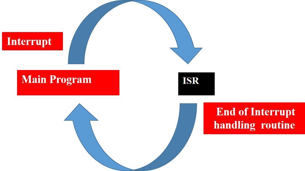
An example can be that of pressing a push button or motion detection with a PIR Sensor. In both cases, a push button or a PIR motion sensor can be used to trigger an interrupt. Therefore, when an external event occurs, the processor stops what it is doing and executes the interrupt service routine which we define for the respective event. After that, it returns to the current program. External Interrupts are extremely useful because with their help we do not have to constantly monitor the digital input pin state.
In summary, the use of external GPIO interrupts makes the embedded system event-driven and responsive. They make use of the microcontroller’s processing time and computing resources efficiently.
8051 Interrupt Types
The 8051 microcontroller can recognize six different types of events. These events can request the microcontroller to temporarily stop the execution of the current program and instead run a special block of code first. The interrupt sources present in 8051 microcontrollers are:
- Reset interrupt
- Timer0 overflow interrupt, TF0
- Timer1 overflow interrupt, TF1
- External hardware interrupt, INT0
- External hardware interrupt, INT1
- Serial communication interrupt, (RI/TI)
The 8051 microcontroller generates the timers and the serial interrupts internally. While the external interrupts are generated via externally interfacing devices or switches that are connected to the microcontroller, these external interrupts can be edge-triggered or level-triggered.
8051 microcontroller Interrupt Service
A fixed memory area is assigned for each interrupt inside the microcontroller. The Interrupt Vector Table contains the starting address of the memory location of every interrupt. When an interrupt occurs, the controller transfers the contents of the program counter onto the stack. Then it jumps to the memory location, which is specified by the Interrupt Vector Table (IVT). The code written in this memory area by the programmer starts its execution. We refer to this code as an Interrupt Service Routine (ISR) or an interrupt handler on the 8051 microcontroller.
Interrupts 8051 microcontroller Vector Table
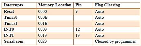
- RESET INTERRUPT: When the reset pin activates, the program execution flow jumps to execute code from the 0000H memory location. Generally, we don’t use this pin. It is also known as power-on reset.
- TIMER INTERRUPTS: Two timers (T0 and T1) are present in the 8051 microcontroller and are responsible for a Timer interrupt. A timer interrupt informs the microcontroller that the corresponding timer has finished counting. Memory locations 000BH and 001BH in the interrupt vector table belong to Timer0 and Timer1, respectively.
- EXTERNAL INTERRUPTS: There are two external interrupts (INT0 and INT1) to serve external devices. Pin numbers 12 and 13 in port 3 are for the external hardware interrupts. Both of these interrupts are active low. An external interrupt informs the microcontroller that an external device needs routine service. Memory locations 0003H and 0013H in the interrupt vector table belong to INT0 and INT1, respectively.
- SERIAL INTERRUPT: This interrupt is useful for serial communication. It has a single interrupt that belongs to both receive and transmit. When enabled, it notifies the controller whether a byte has been received or transmitted. This interrupt vector table assigns location 0023H to this interrupt.
Interrupt Enable (IE) Register 8051 Microcontroller
REGISTER CONFIGURATION (for interrupt selection): Now we have to specify the microcontroller, which interrupts to serve. We can use all of the above interrupts by configuring some bits in a special function register known as the Interrupt Enabled (IE) register. These registers enable or disable the various available interrupts.

| Interrupt Enabled Register | Configuration |
|---|---|
| EA – Enable Interrupt | The EA bit must be set to 1 to enable any of the interrupts. By default, all interrupts are disabled. If EA = 1, it means enable interrupt, and if EA = 0, it means disable Interrupt. |
| ET2 – Timer2 interrupt enable bit | Enable or disable Timer2 overflow or capture interrupts only in 8052. In AT89C51, there are only two timers, so ET2 is not used. |
| ES – Serial port interrupt enable bit | Enable or disable serial port interrupts. |
| ET1 -Timer1 interrupt enable bit | If ET0 = 1, enable the Timer1 overflow interrupt, and if ET0 = 0, disable the Timer1 overflow interrupt. |
| EX1- External interrupt INT1 enable bit | If EX1 = 1, Enable INT1, and if EX1 = 0, Disable INT1. |
| ET0: Timer0 interrupt enable bit | ET0 = 1, Enable Timer0 overflow interrupt ET0 = 0, Disable Timer0 overflow interrupt. |
| EX1: External interrupt INT0 enable bit | EX1 = 1, Enable INT0; EX1 = 0, Disable INT0. |
Interrupt Service Routine
When we specify an interrupt, the next step is to tell the microcontroller what to do when an interrupt occurs. For this, we write a subroutine or a function for the interrupt, which is interrupt service routine, or ISR. The 8051 microcontroller automatically calls this function when an interrupt occurs. The definition of subroutine must have the keyword interrupt with the interrupt number. Each interrupt has a specific subroutine number.
External Interrupts of 8051 Microcontroller
Since we already discussed how to use timers in 8051, in this article we will just talk about how to use external interrupts in 8051. The microcontroller receives the external interrupts from the externally interfaced devices at the INTx pins. These interrupts can be level-triggering or edge-triggering, we can decide this by the TCON register.
- For level-triggering, an interrupt activates for a low signal at the INTx pin.
- For edge-triggering, an interrupt is activates for a high-to-low transition at the INTx pin.

TCON Register
Setting the IT0 and IT1 bits makes the external interrupt 0 and 1 edge-triggered, respectively. By default, these bits are set to 0, so the external interrupt is level-triggered.
IT1: External interrupt 1, signal type control bit.
IT1 = 1; // Enable external interrupt 1 to trigger by a falling edge signal.
IT1 = 0; // Enable a low level signal on external interrupt 1 to generate an interrupt.
IT0: External interrupt 0, signal type control bit, same as IT1.
IT0 = 1; // Enable external interrupt 0 to trigger by a falling edge signal.
IT0 = 0; // Enable a low level signal on external interrupt 1 to generate an interrupt.
How to Configure External Interrupt on 8051 Microcontroller
- Enable external interrupt 0 or external interrupt 1 by configuring the IE register. For this, we have to give the command as follows:
IE=0x81; // For INT0
IE=0x84; // For INT1 - Now we have to write a routine for an external interrupt. For EX0 (INT0), the interrupt number is 0, and for EX1 (INT1), the interrupt number is 1. For using external interrupt INT0, we have to write the routine as follows:
void ISR_ex0(void) interrupt 0For using external interrupt INT1, we have to write the routine as:
void ISR_ex1(void) interrupt 2- For edge-triggering external interrupts, IT0 or IT1 is set to 1.
IT0=1; // For INT0
IT1=1; // For INT1Proteus Schematic
In this section, we have provided the Proteus schematic used for simulation. You need to connect the circuit according to this schematic for the code to work.
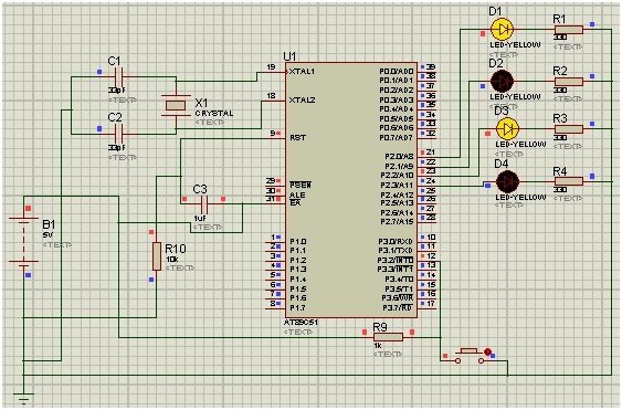
We used the external interrupt INT0 of the 8051 microcontroller. Port 2 is used to monitor the output. In the beginning, we pass the alternate values to the P2 LEDs. When the external interrupt is provided through a push button, the Interrupt service routine starts to execute, and the LED output will toggle for 1 sec. This 1-second delay is given through timer 0 using mode 1.
8051 Microcontroller External Interrupts Code
#include<reg51.h>

sbit led1 = P2 ^ 0; // Port 2, Pin 0
sbit led2 = P2 ^ 1; // Port 2, Pin 1
sbit led3 = P2 ^ 2; // Port 2, Pin 2
sbit led4 = P2 ^ 3; // Port 2, Pin 3

void ISR_ex0(void);

void Delay();

void main()
{
  P0 = 0x00; // Make all pins zero
  P1 = 0x00; // Make all pins zero
  P2 = 0x00; // Make all pins zero
  P3 = 0x04; // making Port3 pin 2 high
  IE = 0x81; // Enable INT0
  IT0 = 1; // Set Falling Edge Trigger for INT0
  while (1)
{
    led1 = 1;
    led2 = 0;
    led3 = 1;
    led4 = 0;
  }
}

//  Interrupt service routine function
void ISR_ex0(void) interrupt 0 // ISR for external interrupt INT0
{
  led1 = ~led1;
  led2 = ~led2;
  led3 = ~led3;
  led4 = ~led4;

  Delay();
}

//  Initialize delay with timer0
void Delay()
{

  int i;
  TMOD = 0x01; // Timer0 mode1

  for (i = 0; i < 200; i++) {
    TH0 = 0xF8; //initial values for 1sec delay
    TL0 = 0xCC;
    TR0 = 1; // timer0 start

    while (TF0 == 0); // check overflow condition
    TR0 = 0; // Stop Timer
    TF0 = 0; // Clear flag
  }
}
Code Explanation
In this section, we will explain how each part of the code works in detail.
#include<reg51.h>

sbit led1 = P2 ^ 0; // Port 2, Pin 0
sbit led2 = P2 ^ 1; // Port 2, Pin 1
sbit led3 = P2 ^ 2; // Port 2, Pin 2
sbit led4 = P2 ^ 3; // Port 2, Pin 3

void ISR_ex0(void);

void Delay();
In the first line, we add a header < reg51.h>, which helps us deal with the registers of the 8051 microcontroller. Next, we declare 4 pins of Port 2 for LEDs. In the end, we declare two functions: an Interrupt Service Routine and a Delay.
void main()
{
  P0 = 0x00; // Make all pins zero
  P1 = 0x00; // Make all pins zero
  P2 = 0x00; // Make all pins zero
  P3 = 0x04; // making Port3 pin 2 high
  IE = 0x81; // Enable INT0
  IT0 = 1; // Set Falling Edge Trigger for INT0
  while (1)
{
    led1 = 1;
    led2 = 0;
    led3 = 1;
    led4 = 0;
  }
}
In the void main function, we set all the pins of the first 3 Ports to zero, while we set the pins of Port 3, pin 2, to high. Next, we set the Interrupt enable register for INT0 and the interrupt type to edge trigger. In the while loop, we set led1 and led3 as high, whereas led2 and led4 are set as low.
//  Interrupt service routine function
void ISR_ex0(void) interrupt 0 // ISR for external interrupt INT0
{
  led1 = ~led1;
  led2 = ~led2;
  led3 = ~led3;
  led4 = ~led4;

  Delay();
}
Now, we set the ISR function; in this, we have assigned a toggle to the LEDs with a delay. This ISR function will work when an external interrupt is provided to interrupt 0.
//  Initialize delay with timer0
void Delay()
{

  int i;
  TMOD = 0x01; // Timer0 mode1

  for (i = 0; i < 200; i++) {
    TH0 = 0xF8; //initial values for 1sec delay
    TL0 = 0xCC;
    TR0 = 1; // timer0 start

    while (TF0 == 0); // check overflow condition
    TR0 = 0; // Stop Timer
    TF0 = 0; // Clear flag
  }
}
Lastly, we have the delay function. In this function, we have set the timer mode to 1. Next, we have set the high bit and low bit for a 1-second delay in the for loop. Then we start the timer 0 using TR0 = 1. In the while loop, we check for the overflow condition, which is TF0 == 1, and the delay function ends.
Conclusion
Here is a summary of the topics we have covered in this article:
- 8051 microcontroller interrupt and its types
- Interrupt service and vector table of the 8051 microcontroller
- Interrupt Enable register and ISR
- step-by-step guide for writing code
- Proteus Schematic
- code and explanation
Related Articles:
If you liked reading this article, we have provided links to similar articles below:
- How to download and install KEIL uVision for ARM and 8051.
- Serial communication 8051 microcontroller using KEIL.
- Servo motor interfacing with 8051 using KEIL compiler.
- KEYPAD INTERFACING 8051 MICROCONTROLLER with code.
- INTERFACING ADC 0804 with 8051 MICROCONTROLLER.
This is all about how to use interrupts on the 8051 microcontroller. If you encounter any issues with programming or simulation, please let us know with your comments. In the next tutorials, we will cover more interesting applications of the 8051 microcontroller.
Hi, can u rearrange the code to turn on led at starting point for 1 second and after switch on the led need to off for 2 second. Then back to on stage.
good evng sir,
for 1 sec delay i take
for(i=0;i<15;i++)
tl0=0xff;
th0=0x0f;
why it don't works?
in general i applied it for many programs ,it works also.
Hi
By using this function, the delay depends on the microcontroller frequency or crystal oscillator.
Sir can you please help me to write the code of this question
1.When the key INT0(P32) is pressed down,realize counter automatically add one and 8 digits counter. (000,001,010,011,100,101,110,111,000,……).(you can use D2,D3 AND D4)
Please please l berg you
Sir can you please help me to write the code of this question
Using microcontroller 8051
Question 2:Display“7”, “8”, “9”in 3 Digital Tubes.
Please please l berg you
sir,it works
thanks for providing this code.
8051 microcontroller program to find power factor of series RC circuit, upon
occurrence of an interrupt find power factor of a series RL circuit
please send the code ….
In the table of Interrupt Enabled Register, the last line is EX1 or EX0 ? I wonder if the EX1 is right. Or It should be EX0?