Solar panels are becoming increasingly popular as a renewable energy source, and accurately measuring their parameters is crucial for monitoring and optimizing their performance. In this article, we will delve into the world of solar panel parameter measurement systems. We will explore the different components and sensors used to measure voltage, current, power, temperature, and light intensity. Additionally, we will discuss the role of a PIC microcontroller and its built-in analog-to-digital converter in obtaining these measurements. Whether you are a solar panel enthusiast or simply curious about the technology behind it, this article will provide you with valuable insights into the measurement process. So, let’s dive in and explore the fascinating world of solar panel parameter measurement systems!
Block Diagram
The block diagram above displays a solar panel measurement system. The system utilizes a voltage divider to measure voltage, incorporating a polar and non-polar capacitor to mitigate rapid voltage fluctuations during measurement. It employs a difference amplifier to measure current, utilizing a shunt resistor for signal conditioning and conversion of current into voltage. To measure the voltage of the solar panel, an LM35 temperature sensor is utilized. The system also employs a light-dependent resistor to measure light intensity. Power can be calculated by multiplying the measured current and voltage.
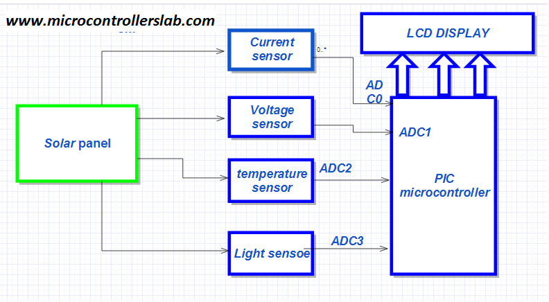
The PIC microcontroller connects sensors to four ADC channels, as illustrated in the block diagram above. The following section will explain how these sensors work, and the circuit diagrams for all of these sensors are depicted below.
Voltage Sensor Circuit Diagram
There are many ways to sense voltage. But in this project, we can easily measure the voltage of a solar panel using a voltage divider. Two capacitors are connected in parallel to the voltage measurement resistor to avoid voltage fluctuations and prevent harmonics from entering the ADC of the PIC microcontroller. I have already posted an article on how to measure AC voltage using a PIC microcontroller. You can also check out this article by clicking on the link below:
Circuit diagram of a voltage sensor is shown below:

According to the voltage sensor formula, for a solar panel of 24 volts, the values of the voltage divider resistors are R2 = 10K and R4 = 2K. The reason I have used a voltage divider is because the maximum input voltage to the Analog to Digital Converter can never be greater than 5 volts. However, I calculated these resistor values according to 4 volts to increase the accuracy of the measurement and to ensure the protection of the ADC in case of greater voltage fluctuation.
Note: DC voltage source is used instead of solar panel in Proteus just for simulation purpose. Because solar panel simulation is not available in Proteus.
Current Sensor Circuit Diagram
Below is a circuit diagram of a current measurement circuit. I have used a differential amplifier to amplify the voltage appearing across the shunt resistor. Since the current value may vary at different times, generating different voltages across the shunt resistor, it is not possible to use a voltage divider as we do not know the current values.
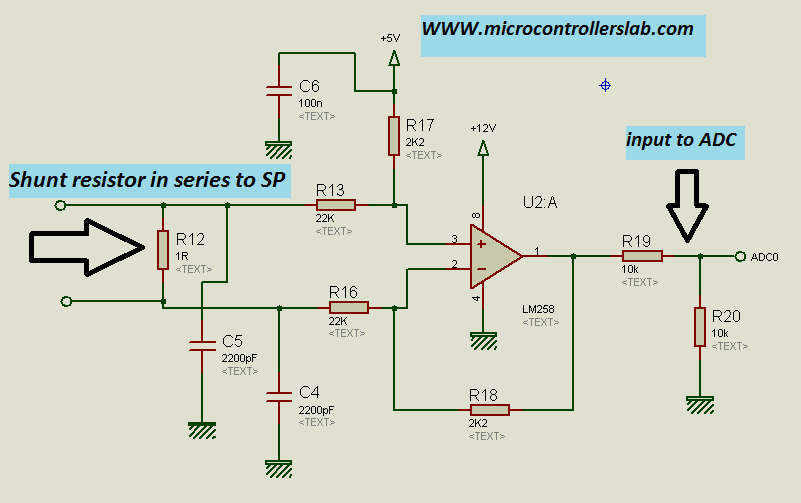
I have already posted an article on how to measure AC current using a differential amplifier. You can check the following article to understand how the above circuit is working.
Temperature Sensor Circuit Diagram
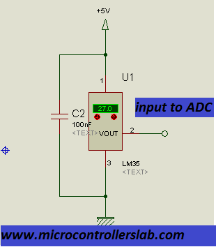
The Circuit Diagram of a temperature sensor is shown below. To learn more about the temperature sensor and its details, please read the following articles:
- Digital temperature sensor using PIC microcontroller
- Wireless temperature sensor using PIC microcontroller and gsm
Light Sensor Circuit Diagram
Light dependent resistor is used to measure the intensity of light. LDR is a light-controlled variable resistor. The resistance of LDR changes with the change in the intensity of light. The greater the intensity of light, the lower the resistance will be, and the lower the intensity of light, the greater the resistance will be. The change in resistance can be easily measured by converting it into voltage form as shown in the circuit diagram below.
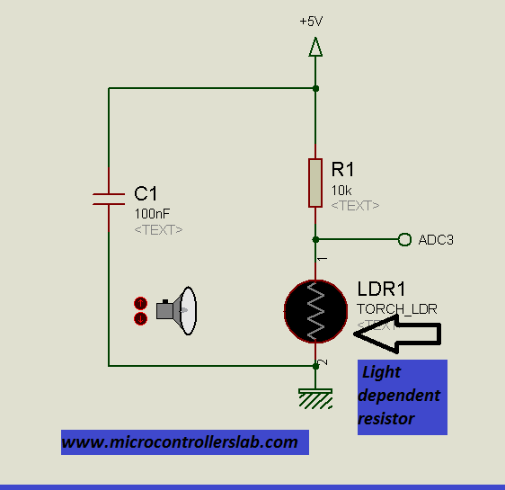
In the above circuit, a non-polar 100nF capacitor is used to prevent voltage fluctuations.
Power Measurement
You can easily calculate the output power of a solar panel by multiplying the voltage and current outputs of the solar panel. This calculation is possible because a solar panel functions as a DC voltage source, where the voltage and current remain in phase. This simplifies the power relationship to a straightforward multiplication of the voltage and current. You can perform these calculations with the assistance of an algorithm or program.
Solar Panel Parameters Measurement Circuit Diagram
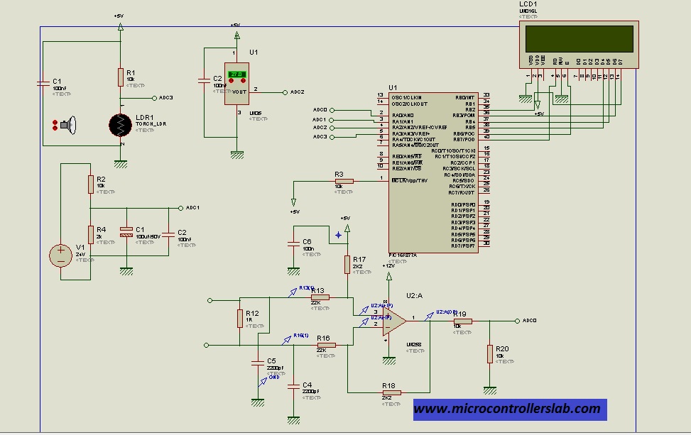
A complete circuit diagram of solar panel voltage measurement is shown below. You can easily write code for this circuit using the ADC of a PIC microcontroller and an LCD display for digital display of these values.
The circuit diagram consists of several components and sensors connected to a PIC microcontroller, which is responsible for measuring and processing the analog values obtained from the sensors. Overall, this circuit diagram illustrates the connections and components involved in measuring the parameters of a solar panel using a PIC microcontroller and corresponding sensors. It provides a visual representation of the system for better understanding and implementation.
If you want to purchase the complete circuit diagram and code for this project, please comment on this post with your email address: microcontrollerslabhub@gmail.com
Conclusion
In conclusion, solar panel parameter measurement systems play a vital role in monitoring and optimizing the performance of solar panels. By accurately measuring parameters such as voltage, current, power, temperature, and light intensity, these systems provide valuable insights into the efficiency and effectiveness of renewable energy generation. The use of a PIC microcontroller and its built-in analog-to-digital converter simplifies the measurement process and ensures precise readings. Whether you are a solar panel enthusiast or simply curious about the technology behind it, understanding the world of solar panel parameter measurement systems opens up a fascinating realm of renewable energy exploration. Take a dive into this captivating field and unlock the full potential of solar power!
You may also like to read:
- Digital DC Voltmeter using 7-Segment Display and Pic Microcontroller
- Alternating Current Measurement using Pic Microcontroller
- DC motor Speed control using pic microcontroller
- Rain Drop Sensor Module Interfacing with Pic Microcontroller– Rain Detector Circuit
- GPS based speedometer using pic microcontroller
- Automatic Temperature controller using pic microcontroller
- Display GPS Co-ordinates on LCD using pic microcontroller
- Home security system using PIR sensor and GSM module
Hi;
Thank you for all of these subjects, actual they are very useful and give me very clear idea about the topic which I try to design. Would you please send to me the code for the topics which has been mentioned above.
Best regards;
I have already posted articles on temperature, voltage and current sensors along with code. you can get from those articles. I will post complete code of solar panel measurement system in few days.
thank u for ur great role here. please send it by my
email address abaynehanjulo12@gmail.com
please can you send me the detailed file of this subject i am currently working for my graduation project. thank you
hi.
dear this is what i want …………….can you send me its simulation,circuit diagram and the most important thing code…….please send me as soon as possible.
id: aalfeen_shahbaz@yahoo.com
thanks,
To download circuit diagram of solar panel parameters measurement system click on link below :
http://www.4shared.com/rar/-PValhUNce/ciruit.html?
I have posted articles on temperature , light , current and voltage measurement separately. you can go through them to write code for this project. Or just combine code of all these sensors to make solar panel parameters measurement system.
Sir,
can you please send the code of above project with using PIC18f4520 or PIC16f877a at email nikhiladsul7@gmail.com
please sir. Thank you.
hey bilal….
will you please send me its simulation file and code…………?
id: tahirnaeem90@hotmail.com
Read above comment for circuit diagram of solar panel parameters measurement system.
can you send me its simulation,circuit diagram and the most important thing code ,please send me as soon as possible.we are doing solar monitoring project for that we want simulation,code and circuit.
email id:anuragmodi12@gmail.com
To download circuit diagram of solar panel parameters measurement system click on link below :
http://www.4shared.com/rar/-PValhUNce/ciruit.html?
I have posted articles on temperature , light , current and voltage measurement separately. you can go through them to write code for this project. Or just combine code of all these sensors to make solar panel parameters measurement system.
hello, i thank you if you send to me he details including the codes .
can you send me its simulation,circuit diagram and the most important thing code ,please send me as soon as possible.we are doing solar monitoring project for that we want simulation,code and circuit.
email id:intizarqasar@yahoo.com
Can u send me code. email: glorious_green@live.com
hi Sir :).. i’m interested to built this … can you please email me the details? and codes? ..
thanks in advance :)..
B_H_O_N_G_2002@yahoo.com
Bhong2002
sir kindly send me the details of the project
ikniazian@gmail.com
pelez send code and complete circuit diagram on this email
kumarravish101@gmail.com
Bilal malik want showing solar panel parameters measurement system, but he don’t want to share code. If he not want to share code. Why share circuit diagram download link, I don’t understand. he he he ha ha ha
pls send the complete code of the project
pls send complete code on the mail id capsunlights@yahoo.com
I like this project. I am working on solar energy system. Every time I need to use voltmeters and current meters for measurement. This project is very good because this gives additional parameters like temperature and light intensity along with this voltage and current. I will implement this hardware, so please send me circuit diagram and code of this project.
Thank you
regards,
Abhijit V. Padgavhankar
plz send me ckt diag and code on abhijit595@rediffmail.com
till i am not getting source code for this project. plz send it on abhijit595@rediffmail.com
faizmustafa67@yahoo.com
sir plz can you tell me , can i do all this stuff using aurdino or avr atmega 16…if yes then kindly help me in this regards…
Yes you can use any microcontroller or arduino you just have to change microcontroller and write code using respective compiler
Thank you very much astonishing work
please SEND me the complete circuit diagram and the CODE
munthersharaiha@gmail.com
Thank you again
Hi.
Can you send me its simulation,circuit diagram and the most important thing code.please send me as early as possible.
my e-mail id is: sumit18691@yahoo.com
Hi Bilal,
Thanks for sharing this knowledge with us. I just have a question and I am confused about it. As you said, the 24V from a solar panel (dc power in this case) goes through a voltage divider circuit which will reduce to 4V since the microcontroller cannot take voltages greater than 5V. Does this mean that the output from the solar panel reduces to 4V in total and the remaining 20V is lost?
plz send me ckt diagram and code for this project
Sir please send me the full code for this project sir. code is not available for dc measurement of current so please send me as soon as possible
solar panel parameters measurement system, i doing coding complete myself…
https://www.dropbox.com/s/pmhpyaxhis51653/Untitled.png?dl=0
pls send complete code
email: akintaspinar@hotmail.com
Hi.
Can you send me circuit diagram for this projects? Thank you so much for share this.
Its a nice topic to work. Thanks for the posting. Kindly send me the circuit diagram and code for the above to this mail. Email: gourabagrawal@gmail.com
Hi.
Can you send me circuit diagram for this projects? Thank you so much for share this.
jawadchorfi93@gmail.com
send me the code for this project. thanks
Email: sardarhafeezurrehman@yahoo.com
Hi Sardar
Its not free you can purchase it from me by contact me at microcontrollerslabhub@gmail.com
contact me at microcontrollerslabhub@gmail.com
Sir can you please send me the code for this project on 8051 or pic .. And the hardware details ..thankyou
Hi sir!
Can you guide me to make this project.
I need your help in coding section( how to wright code to microcontroller and can you plz send me the code also
contact me at microcontrollerslabhub@gmail.com if you need my project assistance
Hi Bilal,
Thank you for your helpful information. I have one questions, How is it possible to remove the possible noise from the environmen which has effect on the measurement system. For example, we implement one measurement system to measure the paramteres fo the solar panels. However, we see some noise around 0.7V during night and date on the output of out measurement system.
Thanks,
RZ
please give me the code
I am working on a similar project….. Would you kindly send me the circuit diagams, simulations and codes on my email please.. I would really appreciate it…… Mainly on solar tracking and monitoring.
Hi
I sent you an email on microcontrollerslabhub@gmail.com
thanks
replied
Hi
I would like to say thank you for your initiatives and your work, it is such an magnificant project.
I would be grateful if you sent me the code to my e-mail: m.alkour@yahoo.com, and
I just wanted to know if I used UNO Arduino mircrocontroller, would this be useful for me ?
thank you
can you send to me code pleaz
center.point.2016@gmail.com
suleiman.shamasneh@gmail.com
i want complete circuit diagram and code of this project please
i want the code of this circuit plzz.
zbs.zizou@gmail.com
hi, can you upload the codes for this project..thank you
hie can you kindly sent circuit diagram and code
you can sent at fcmuzhanye95@gmail.com
Hi,pls send me the complete PDF write up for this project.martinsudek4@gmail.com
you can reach me at my email microcontrollerslabhub@gmail.com
Hi! Great project! May I ask how do you determine the best value for the parallel capacitors attached to the solar panel’s voltage divider? Thank you 🙂
sir is it possible for the sensor to measure voltage up to 300 volts with few modifications?
Sir,
Please send me detail of overall system and circuit diagram.
Thank u.
from where i can get full code of this project please