In this tutorial, we will learn how to use timers on the 8051 microcontroller to generate a delay. The 8051 microcontroller has two 16-bit built-in timers. We can program each timer individually and configure them as either timers (to generate time delays) or counters (to count events occurring outside the microcontroller). The 8051 timer has three general functions, which are as follows:
- Calculating the amount of time between events.
- Counting events.
- Generating the baud rate for the serial port.
Before learning about 8051 timer programming, you should know how to use KEIL for 8051 programming and how to use input and output ports of 8051 microcontroller
Recommended Components
The following parts and reference books are useful for building and learning 8051 microcontroller projects.
| Component | How it’s used in your 8051 projects | Buy on Amazon |
|---|---|---|
| AT89S52 (8051) microcontroller | A modern, in-system-programmable 8051-core MCU that runs the code in these tutorials. | Check Price |
| USBasp programmer (ISP) | Burns the compiled HEX file into the AT89S51/AT89S52 over the ISP header. | Check Price |
| Breadboard | Solderless base for wiring the 8051 and the project’s components. | Check Price |
| Jumper Wires | Make the connections between the MCU, components and power rails. | Check Price |
| Book: The 8051 Microcontroller & Embedded Systems (Mazidi) | The classic 8051 textbook — architecture, assembly & C programming with interfacing examples. | Check Price |
| Book: The 8051 Microcontroller, 3rd Ed. (Ayala) | A popular reference covering 8051 architecture, programming and applications. | Check Price |
As an Amazon Associate we earn from qualifying purchases. Prices and availability are accurate as of the date/time indicated and are subject to change.
Types of 8051 timers

The 8051 microcontroller has two timers: Timer0 and Timer1. Both of these timers are 16-bit each, and we can also use them as counters. In the case of the 8051 microcontroller, its architecture is 8-bit, so the 16-bit timer is accessible as two separate 8-bit registers, low byte, and high byte.
8051 Timer0 Registers
It is a 16-bit register that is accessed as a low byte and a high byte. The low byte is referred to as TL0, and the high byte is referred to as TH0. These registers are accessible like any other register.
8051 Timer1 Registers
Timer1 is also a 16-bit register, which is split into two bytes: a low byte referred to as TL1 and a high byte referred to as TH1.
Note: Both the timers (Timer0 and Timer1) share two common SFRs (special function registers): TMOD and TCON. We will discuss these two SFRs below and see how they control Timer 0 and Timer 1.
8051 Timer Mode (TMOD) Register
This timer can set various timer modes for timer 0 and timer 1. In this 8-bit TMOD register, the 8051 microcontroller assigns the lower 4 bits to Timer1 and the upper 4 bits to Timer0. For each timer, the lower 2 bits set the timer mode, while the upper 2 bits specify the operation.
| Symbol and pins | Functions |
|---|---|
| GATE | This bit controls whether to use an internal or external source for the timer or counter. |
| GATE = 1 | We can start and stop the timer or counter from an external source. |
| GATE = 0 | In this case, we don’t need any external hardware to start and stop the timer or counter. |
| C/T | This bit decides whether the timer is used as a time delay generator or as an event counter. |
| C/T = 0 | The timer (Timer0 or Timer1) is used as a timer. |
| C/T = 1 | The timer (Timer0 or Timer1) is used as a counter. |
MODE Bits M1, M0:

The last two bits for each timer, i.e., M1 and M0, select the timer mode. 8051 has four timer modes, which are as follows:
Mode 0:
- This mode allows a 13-bit timer or counter.
- The Mode0 register can hold values up to 1FFFH in TH-TL.
- When the timer reaches its maximum of 1FFFH, it rolls over to 0000, and the TF (flag bit) is raised.
- Not used generally.
- Aside from these few differences, the rest is similar to Mode 1.
Mode 1:
- This mode enables a 16-bit timer or counter.
- The Mode 1 registers (TL and TH) can store values from 0000 to FFFFH.
- The timer must be started after loading TH and TL with a 16-bit initial value.
- We can give initial values by using “SETB TR0” for timer0 and “SETB TR1” for timer1.
- When the timer starts, it keeps counting until it reaches its limit of FFFFH.
- Once the timer reaches its limit at 0000H, it sets a TF (timer flag) bit: TF0 for timer0 and TF1 for timer1.
- Now we can stop the timer using “CLR TR0” for timer0 and “CLR TR1” for timer1.
- To repeat the process, the original values must be reloaded in the TH and TL registers, and the timer flag must be reset to 0.
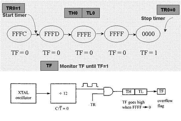
For time delay, the timer uses the clock source frequency of the crystal attached to 8051. The frequency of the timer will be 1/12th of the frequency of the external crystal oscillator.
Mode 2:
- This mode enables an 8-bit timer or counter.
- This timer first loads the values up to FFH in the TH register.
- When TH is loaded, 8051 copies the same 8-bit values to TL.
- The timer starts by setting “SETB TR0” and “SETB TR1” instructions for timer0 and timer1, respectively.
- When the timer starts, it continues to increment the TL register until it reaches FFH; after that, it rolls over to 00 and raises the TF flag. Then the TL is automatically loaded with its original value, which is reserved by the register TH.
- The main feature of this mode is that it repeats the process. We just have to clear the TF register, and it will load the original value into the register. While in mode 1, the programmer reloads the values to TH and TL.
Mode 3:
- This mode is also known as a split timer mode.
- It splits timer0 into two 8-bit timers.
- These 8-bit timers can count from 00H to FFH.
- This mode is used in applications where we require an additional 8-bit timer or counter.
- TL0 sets TF0, and TH0 sets TF1.
- We can program timer0 and timer1 independently in modes 0, 1, and 2. Each timer can have its own settings. But mode 3 can’t work independently.
- If we choose mode 3 for timer0 and place timer1 in mode 3, it will cause the timer to stop counting. Then timer 0 will use TR1 (timer1 register) and TF1 (timer1 flag), i.e., timer 0 has to depend on timer 1.
8051 Timer TCON Register

The second special function register is the timer control register. It is an 8-bit register, and each bit has a special function. The bits, symbols, and functions of every bit of the TCON register are as follows:
| Symbol and Bits | Functions |
|---|---|
| TF1 | Overflow flag for Timer1. |
| TF1 = 1 | Set when timer rolls from all 1s to 0. |
| TF1 = 0 | Cleared to execute the interrupt service routine. |
| TR1 | Run the control bit for Timer1. |
| TR1 = 1 | Turns on Timer1. |
| TR1 = 0 | Turns off Timer1. |
| TF0 | Overflow flag for timer0, same as TF1. |
| TR0 | Run the control bit for Timer0, same as TR1. |
| IE1 | External interrupt 1 Edge flag It is not related to timer operations. |
| IT1 | External interrupt 1 signal type control bit. |
| IT1 = 1 | Enables external interrupt 1 to be triggered by a falling edge signal. |
| IT1 = 0 | Enables a low-level signal on external interrupt 1 to generate an interrupt. |
| IE0 | External interrupts 0 Edge flag. It is also not related to timer operations. |
| IT0 | External interrupt 0 signal type control bit, same as IT1. |
Delay Calculation of 8051 Timer
Timer Clock Source
The timer needs a clock source. If C/T = 0, the crystal frequency attached to the 8051 is the source of the clock for the timer. The value of the crystal frequency attached to the microcontroller determines the speed at which the timer ticks. Now suppose that the crystal frequency is 11.059 MHz.
Timer Clock Frequency
The frequency for the timer is always 1/12th of the frequency of the crystal attached to the 8051.
- TF = 1/12 x 11.059 MHz = 921583 Hz.
Timer Clock Period
The time delay of one machine cycle is given below. We use this to generate the delay.
- TP = 1/921583 = 1.085 µ sec.
Add 10 ms Delay
Here we have explained in 3 steps how we can add a 10 ms Delay using timers:
- Firstly, we divide the desired time delay value (10 ms) by the timer clock period.
- N = 1/1.085us
- N = 10ms/1.0859usec
- N = 9216
- Now we will subtract the value of N from the maximum number of counts possible for the 16-bit timer, i.e., 216 = 65536.
- M = 65536 – N
- M = 65536 – 9216
- M = 56320
- Lastly, we convert this value to hexadecimal and write it in the TH and TL registers.
- MH = DC00H
- TH = D
- TL = 00H
Proteus Schematic – 8051 Timer
In this Proteus schematic, we have simulated this circuit by adding a delay of 10 ms between the on and off states of the LED. The code is provided in the section below.
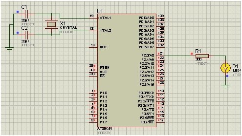
We have set the crystal oscillator’s frequency at 11.059 MHz.
8051 Microcontroller Timer Delay Code
This sketch adds a delay between toggling LED states between on and off. This sketch initializes Port 2’s pin 0 as an LED pin. This sketch also uses mode 1 of timer 0 to add a 10 ms delay between the toggling of LED states.
#include<reg51.h>

sbit led = P2 ^ 0; // led at PORT 2 pin 0

void Delay(void); // Delay function declaration

void main() // main function
{
  led = 0; //output PORT

  while (1) // infinite loop
  {
    led = 1; // LED ON
    Delay();

    led = 0; // LED OFF
    Delay();
  }
}

void Delay()
{
  TMOD = 0x01; // Timer0 mode1
  TH0 = 0xDC; //initial value for 10ms
  TL0 = 0x00;
  TR0 = 1; // timer0 start

  while (TF0 == 0); // check overflow condition
  TR0 = 0; // Stop Timer
  TF0 = 0; // Clear flag
}
Code Explanation
In this section, we will explain each part of the sketch provided above.
#include<reg51.h>
sbit led = P2 ^ 0; // led at PORT 2 pin 0
void Delay(void); // Delay function declaration
In the first part, we include the header file <reg51.h>. This will help us manage the registers of the 8051 microcontroller. In the next line, we have set the LED pin on PORT 2 of the 8051 microcontroller. On the last line, we have declared a function for the delay.
void main() // main function
{
  led = 0; //output PORT

  while (1) // infinite loop
  {
    led = 1; // LED ON
    Delay();

    led = 0; // LED OFF
    Delay();
  }
}
In the void main function, we have first set the LED state to off. Then, in the while loop, we will toggle between the on and off states of the LED. Between changing LED states, we are also calling the Delay function. Now let’s look at the Delay function.
void Delay()
{
  TMOD = 0x01; // Timer0 mode1
  TH0 = 0xDC; // High byte initial value for 10ms
  TL0 = 0x00; // Low byte initial value for 10ms
  TR0 = 1; // timer0 start

  while (TF0 == 0); // check overflow condition
  TR0 = 0; // Stop Timer
  TF0 = 0; // Clear flag
}
The void delay function is quite simple. First, we set the timer mode, which we have set to 1 for timer 0 in our case. Then we set the initial values for the low byte and the high byte to achieve a 10 ms delay. After this, we start this timer using TR0 = 1. Now in the while loop, we check for the overflow condition; once the timer reaches overflow, it goes back to the void main function.
Video Demonstration
Conclusion
In this tutorial, we have covered the following topics:
- 8051 microcontroller timers and their types.
- TMOD and TCON registers.
- Modes of timers and delay calculation.
- Proteus Simulation.
- Sketch and its explanation.
Related Articles:
If you liked reading this article, please check these similar links:
- 8051 Microcontroller tutorials in c programming examples
- How to download and install Keil uVision for ARM and 8051
- serial communication 8051 microcontroller using KEIL
- servo motor interfacing with 8051 using KEIL compiler
- DC MOTOR INTERFACING WITH 8051 MICROCONTROLLER
- Timers of PIC microcontroller How to generate delay
This concludes our tutorial, if you face any issues while following this tutorial, let us know in the comment section below.
Thank you Sir.
How can be external frequency can be counted using 8051 mc?
how can we make delay in seconds?