wireless electronics notice board using gsm with scrolling display is widely at public places for displaying the public information. No doubt, electronic display is a common way to display notice but this is not a flexible option for displaying messages or information instantly. Here we have been introducing a modern and advanced wireless control notice board for this specific purposes. wireless electronics notice board is used to provide opportunity for user to change message on notice board by simply sending message from mobile. We will start with basic introduction of with gsm based project. you can check a list of embedded system projects for more details.
Wireless Electronics Notice Board abstract
The main purposes of design this electronic notice board system is to interface with user mobile phones for displaying the latest information. In other words, the user can easily send the message or information for displaying from remote areas. In this system, the user sends the information or data from remote areas and this information or data is received by the sim loaded into GSM modem which is basically receiving end. This system is designed with PIC family pic18f452 microcontroller, which is interfaced with GSM modem and level shifter through serial cable. LCD is also used in this system for displaying the information or data.
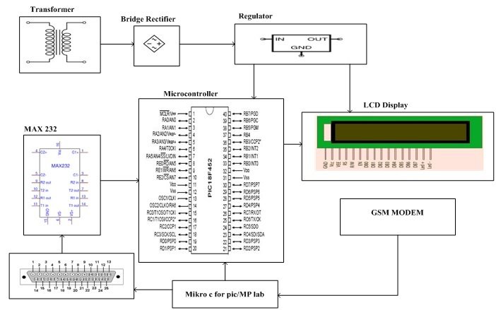
Block Diagram Wireless Electronics Notice Board
The block diagram of wireless electronics notice board is shown in figure
The further information and detail about this specific design is given below for each and every component used in this electronics project.
Components List of Wireless Electronics Notice board
This specific design has following components
- Transformer
- Bridge Rectifier
- Voltage Regulator
- Pic Microcontroller 18F452
- Max 232
- GSM Modem
- LCD Display
Transformer:In this wireless electronic notice the transformer,which consists of two winding’s primary and secondary is used for converting the 220V to 12V ac because this system is directly connected to the wapda power supply.
Bridge Rectifier:The bridge rectifier, which consist of four didoes is used for converting the ac voltages into dc for providing the power to the other components.
Voltage Regulator:The voltage regulator is used for providing the fix 5 volts, to the microcontroller and LCD display. In the absence of voltage regulator, the higher voltage may be damage the LCD display or microcontroller and in this system these two components are too much important.
Pic Microcontroller 18F452:18F452 is very popular and 8-bit microcontroller belongs to pic a family. It is 10-bit microcontroller which has self-programming, 250 bytes of EEPROM and 40MHz maximum speed. It also has 8 channel of analog to digital converter(A/D), two PWM functions and synchronous serial port for serial communication. The synchronous serial port can also be configured either for 3 wire serials peripheral interface (SPI) or 2 wire inter integrated circuit bus and addressable universal asynchronous transmitter receiver. All these features in this microcontroller make this ideal for monitoring and instrumentation, power conditioning, data equation, manufacturing equipment, environmental monitoring, telecoms and consumer audio video applications.
Max232: Max 232 is a 16-pin dip package, which consists of three major blocks and is powered by 5 volts’ supply. It is mostly used in embedded system for serial communication. The problem is occurred when we communicate between TTL logic and CMOS logic because, here in wireless electronic notice board we are communicating between GSM modem and microcontroller therefore the problem would be occurred. For solving this problem, the max 232 is used in this specific wireless electronic notice board.
GSM Modem: The GSM modem is a wireless modem, which can’t work without wireless network. This modem works like a dialup modem and sim is required for communication. In dialup modem the data is send or received through the fix telephonic line but in GSM modem data is send or received though the radio waves.
LCD Display: LCD means the liquid crystal display, which is thin flat display device and is made up of any number of colure or monochrome pixels’ array in front of light source or reflector. In 4-bit data bus the LCD have required 7 data lines,3 lines for control and 4 lines for data bus. In 8-bit data bus, the LCD have required 11 data lines ,3 for control and 8 for data bus.
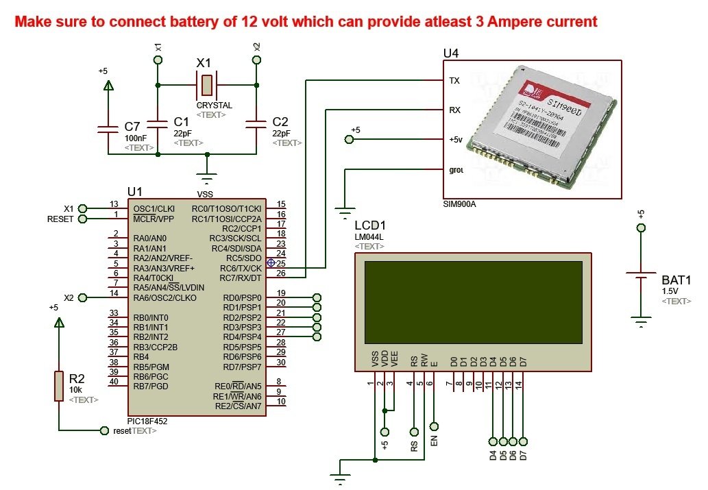
Circuit diagram of wireless electronic notice board
Below is a circuit diagram of wireless electronics notice board with gsm and pic microcontroller. You simply need to connect Gsm module Rx pin with tx pin of microcontroller and vice versa. But you should make should the operating voltages of both devices should be same. If both devices operate on different operating voltages, you need to connect a voltage divider circuit between them or any other circuit to make operating voltage adjustment.
Working video of wireless electronic notice board using gsm module
If you want to check real time demonstration of this pic microcontroller based project. Check out this video.
Working of Wireless Electronic Notice Board using gsm module
The wireless electronic notice board consists of several components which have discussed deeply in above section and here we would be talk about the working of this wireless electronics notice board. When the message or data is send from any smart mobile phone then this message or data is received by the GSM modem, which is sim based. In GSM modem the baud rate is set 4800 bps by using the command AT+IRP= 4800 but now the ECHO should be tuned off by using the command ATE/ATE0 at hyper terminal. The message or data is read by the microcontroller pic18F452 through the max 232, which is only used for serial communication, means for transmission or reception the data.In microcontroller for setting the baud rate 4800bps we set the timer 1 at FF0.The TCON and SCON registers are set accordingly.The LCD is interfaced with the pic18F542 for displaying the message or data, which is sends by user from mobile phone from remote areas. The programming language C have been used in this specific design. The whole design is powered up through 220Volts ac but these voltages are stepdown through the transformer and then converted into dc. These dc voltages are provided to the LCD and microcontroller through the voltage regulator. The LM 7805 voltage regulator used in this wireless electronic notice board.
Wireless electronic notice board code
Applications of Wireless Electronics Notice Board with gsm
The wireless electronic notice board have different applications some of which are considering here.
Airports: The wireless electronics notice board is mainly used at airports for conveying the information about the flights timing or any other public notice and all this can be easily done through the mobile phone.
Railways Stations: The wireless electronics notice board is also used at railway station for displaying the information about railway timing or displaying any notice about government policy and railway headquarter.
Shopping Malls: The wireless electronics notice board is also used in shopping malls for display information about the shopping things rates and location of things wirelessly.
Schools and Colleges: The wireless electronics board is used in schools and colleges for displaying the information for students wirelessly.


Where is code?
Can I get the code
where is source code sir
Very nice!
Good day can’t seem to find the source code
coding where?
where is the code please uplode sorce code
http://store.microcontrollerslab.com/product/wireless-electronics-notice-board-using-gsm-with-code/
how can i have the source code.am very much intrested in been part
Sir pls provide the source code. Without code this project will not help us in any way , so please please provide code