In this tutorial, we will learn how to interface PIR Motion Sensor with Raspberry Pi Pico and use GPIO pins of Raspberry Pi Pico as output pins as well as input pins. Accordingly, we will also show how to control an LED via a PIR motion sensor with a Pi Pico board. We will be reading the value from the motion sensor and lighting up the LED accordingly. Hence, the motion sensor’s terminal will act as a digital input and the LED will act as a digital output.

Recommended Components
The following components are used in this project or are helpful for getting started with Raspberry Pi Pico development.
| Component | How it’s used in this project | Buy on Amazon |
|---|---|---|
| Raspberry Pi Pico | The RP2040 board reading the sensor and driving the LED. | Check Price |
| PIR Motion Sensor | Passive infrared sensor that detects motion. | Check Price |
| 5mm LEDs | LED switched on when motion is detected. | Check Price |
| 220 Ω Resistors | Current-limiting resistor in series with the LED. | Check Price |
| Breadboard | Solderless breadboard for assembling the circuit. | Check Price |
As an Amazon Associate we earn from qualifying purchases. Prices and availability are accurate as of the date/time indicated and are subject to change.
Prerequisites
Before we start this lesson make sure you are familiar with and have the latest version Python 3 in your system, have set up MicoPython in Raspberry Pi Pico, and have a running Integrated Development Environment(IDE) in which we will be doing the programming. We will be using the same Thonny IDE as we have done previously when we learned how to blink and chase LEDs in micro-python. If you have not followed our previous tutorial, you check here:
If you are using uPyCraft IDE, you can check this getting started guide:
Raspberry Pi Pico GPIO Pins
Raspberry Pi Pico exposes 26 multi-function GPIO pins from a total of 36 GPIO pins available in RP2040 microcontroller. Out of these 26 pins, 23 pins are digital pins, and only 3 pins have analog read capability. These digital pins are marked as GP0, GP1, and up to GP22. GP23, GP24, and GP25 are not exposed on the pinout. Therefore cannot be used. GP26, GP27, and GP28 are the next digital pins available. These 26 GPIO pins can be used both in digital input and digital output mode.

PIR Motion Sensor with Raspberry Pi Pico
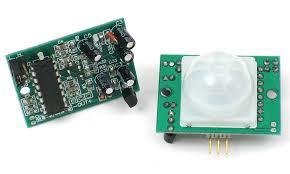
There are many PIR sensors available in the market but we are using passive PIR motion sensors in this project. It can detect a human motion within a range of 10m very easily. It has three pins and the function of each pin is described below:
- GND: It is a ground pin and you should connect it with the ground of your Raspberry Pi Pico.
- VDD: It is a power supplier pin and you should connect it with 3.3V pin of Raspberry Pi Pico.
- Output: It is an output pin of the PIR sensor. Basically, we get output from this pin. We will connect it with one of the GPIO pins of our Raspberry Pi Pico.
PIR Motion Sensor Working
PIR sensor is a low-cost motion detector sensor. It is a passive motion sensor which means it can only detect something around it and it cannot transmit anything. Whenever there is a motion around the sensor, it will detect the heat of the human body and produces a high output logic 1 at the output of the sensor. Every object emits infrared rays when they are heated and on the same principle, the human body emits IR rays due to body heat. Hence, whenever the motion sensor detects the human body around it, its output becomes high. We can also adjust the sensitivity of this sensor by changing the variable resistors available on the sensor. One variable resistor is for sensitivity adjustment of distance and another variable resistor is for sensitivity adjustment of time which is the amount of time for which the output should be high.
Interfacing PIR Motion Sensor and LED with Raspberry Pi Pico
The following components are required:
- Raspberry Pi Pico board
- One PIR Sensor
- One 5mm LED
- One 220 ohm resistor
- Breadboard
- Connecting Wires
Assemble your circuit as shown in the diagram below:
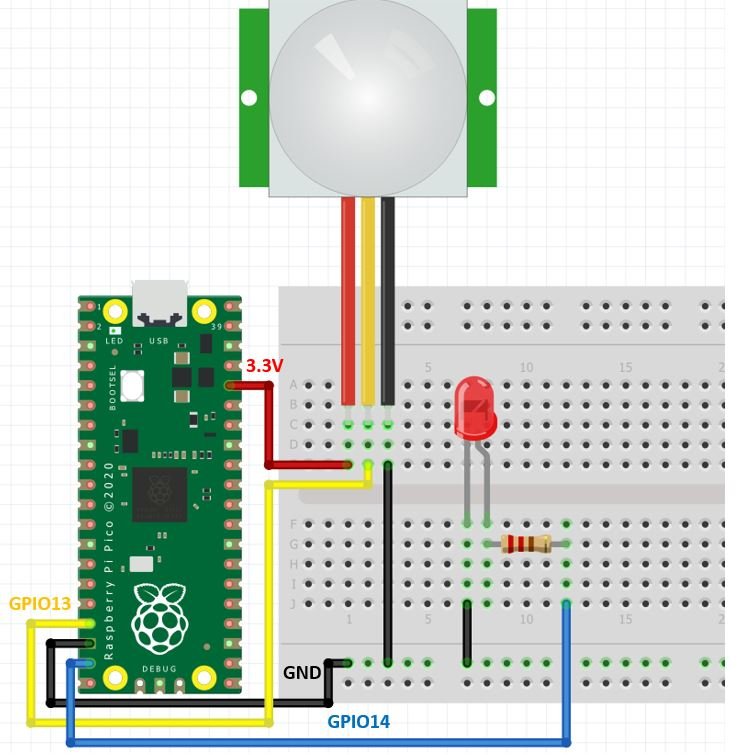
In the above schematic, we can see that GPIO14 is connected with the anode pin of LED through the 220 ohm resistor, and the cathode pin is connected with the common ground.
The PIR Sensor which we are using in this tutorial consists of three pins. Two of them are power supply pins such as VCC and ground pins. We can power the PIR motion sensor directly from the Raspberry Pi Pico 3.3V power pin as shown in the above schematic diagram. The centre pin is an output pin which provides an active high pulse whenever motion is detected. Otherwise, this pin remains active low.

When motion is detected, a logic state of high (1) will be passed on GPIO13 and the sensor input will be in a high state. When the button is released a logic state of low (0) will be passed on GPIO13 and the motion sensor input will be in a logic state LOW. We will read these two states of the motion sensor and turn on and turn off the LED accordingly.

MicroPython Sketch: Raspberry Pi Pico Control Digital Output (LED) through Reading Digital Input (PIR Motion Sensor state)
Create a new file in uPyCraft or Thonny IDE and copy this code to your newly created file. After that download and run this MicroPython script on Raspberry Pi Pico.
from machine import Pin
from time import sleep

LED = Pin(14, Pin.OUT)
PIR_sensor = Pin(13, Pin.IN, Pin.PULL_UP)
LED.low()
sleep(3)

while True:
   print(PIR_sensor.value())
   if PIR_sensor.value() == 0:
       print("Motion Detected! -> LED is now ON")
       LED.high()
       sleep(5)
   else:
       print("No motion detected -> LED is OFF")
       LED.low()
       sleep(1)
How the Code Works?
Importing MicroPython Libraries
Now, let’s see the working of a MicroPython script. We will import the library for the Pin class from the machine module. To interact with the input/output GPIOs we will import the machine module that contains classes to interact with the GPIOs. We should also import the sleep module to insert delay in our MicroPython script.
from machine import Pin
from time import sleep
Configuring Digital Input/Output
The Pin() class takes four parameters as shown below:
Pin(Pin_number, pin_mode, pull, value)- First argument is a pin number to which we want to configure in different modes such as input, output, etc.
- Second argument defines the pin mode such as digital input (Pin.IN), digital output (Pin.OUT), open-drain (OPEN_DRAIN).
- Third argument specifies if we want to enable pull-up and pull-down internal resistor of a GPIO pin. These pull-up and pull-down resistors become handy when we want to use GPIO pins as a digital input pin (PULL_UP, or PULL_DOWN).
- Last argument defines the initial state of GPIO pin as either active high (1) or active low (0). But, by default, the GPIO initial state on reset is 0 (active low).
Define Digital Output
To set a GPIO on or off, we will set it as an output. The first argument in the Pin() class is the pin number on which we are configuring the output. The output is on GPIO14 which is connected to the LED. The second argument shows the pin mode e.g. digital input or digital output mode. As we are configuring GPIO14 as the digital output we gave it as ‘Pin.Out’. This is stored in the object ‘LED’.
LED = Pin(14, Pin.OUT)Define Digital Input
To get the value of a GPIO, we will create a Pin object ‘PIR_sensor’ and set it as an input using ‘Pin.IN’ as the second argument in our Pin() class. The input is on GPIO13 which we specified in the first argument and is connected to the PIR motion sensor. The third argument enables the pull-up resistor on this pin which enables a high state on the motion sensor pin.
PIR_sensor = Pin(13, Pin.IN, Pin.PULL_UP)Here, we have set GPIO14 (connected to the LED) to a low state and provided a delay of 3 seconds for the sensor to stabilize.
LED.low()
sleep(3)
Inside the loop, we access the PIR motion sensor’s state by using the value() function from the Pin class through the “PIR_sensor” object. This will get printed in the shell terminal of our IDE.
print(PIR_sensor.value())If the sensor’s state is 0, that means motion is detected by the sensor and we turn on the LED for 5 seconds. The shell terminal will print the message: Motion Detected! -> LED is now ON.
If the sensor’s state is 1, that means motion is not detected by the sensor, so the LED remains OFF. The shell terminal will print the message: No motion detected -> LED is OFF. We will have a delay of 1 second and then the loop continues to check for motion detection.
while True:
   print(PIR_sensor.value())
   if PIR_sensor.value() == 0:
       print("Motion Detected! -> LED is now ON")
       LED.high()
       sleep(5)
   else:
       print("No motion detected -> LED is OFF")
       LED.low()
       sleep(1)
Demonstration
Now create a new file in uPyCraft IDE or Thonny IDE and upload this MicroPython Script to Raspberry Pi Pico. You will see that the LED remains OFF when no motion is detected and when the PIR sensor detects motion, LED stays ON for 5 seconds.
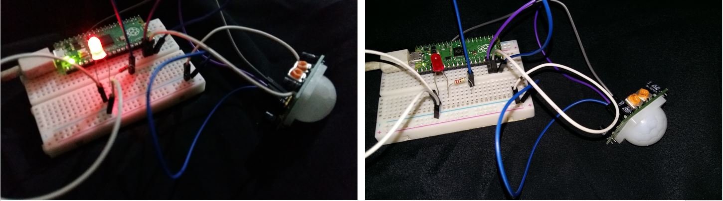
We can view the motion detected messages in the shell console.

You may also like to read:
- Raspberry Pi Pico GPIO Programming with MicroPython – LED Blinking Examples
- Interface Push Button with Raspberry Pi Pico and Control LED
- Raspberry Pi Pico ADC with Voltage Measurement Examples
- TM1637 4-Digit 7 Segment Display Module with Raspberry Pi Pico
- Raspberry Pi Pico PWM MicroPython LED Fading Examples
- Interface Analog Joystick Module with Raspberry Pi Pico
Other PIR motion sensor related articles: