In this tutorial, we will explain the workings of clusters in LabVIEW. Structures in the C language are named clusters in LabVIEW. At the start, we have provided a brief explanation of clusters. After that, we tried to explain the working principles of clusters using a simple example. At the end of the tutorial, we have provided an exercise for you to do by yourself, and in the next tutorials, we will assume that you have done those exercises and not explain the concept regarding them.
Introduction to Cluster Functions of LabVIEW
Data elements of different types stored in one place result in a cluster, or simply, we can say a group of data is known as a cluster. In LabVIEW, an error cluster, which combines a Boolean value, a numeric value, and a string, is an example of a cluster. Those who are familiar with any other programming environment must be well aware of the term structures.
In LabVIEW, a cluster is the same thing as a structure in any other programming language. We can say that clusters are block diagram representations of a structure. Arrays are types of variables that can hold several data items of the same kind. Similarly, another data type available in the C language that allows us to combine data items of different kinds is structure, which we call cluster in LabVIEW.
We have studied arrays in detail in previous tutorials; a cluster can either be a control or an indicator depending upon the need and its use; their function is similar to that of an array. However, clusters have a fixed size, whereas arrays can vary in size; this is one of the major differences between clusters and arrays. Also, note that one array can only have one data type; however, in one cluster, we can store as many different types of data as we want.
Examples of Cluster Functions in LabVIEW
Firstly, we will explain the workings of the cluster function with the help of VI. Create a program or VI as discussed in Tutorial 1 and save it for future use, as we have been doing in all previous tutorials. Right-click on the block diagram, and from the function palette, select Clusters and then select Bundle. See the figure below.

In the cluster section, we can see various blocks, namely bundle, unbundle, bundle by name, unbundle by name, cluster array, and cluster constant. We will try to explain as many as we can, and we will leave the rest for you as an exercise in the exercise section.
The use of bundle blocks is to form a cluster. As the name suggests, a bundle is used to bundle or pack up all the different data types in one place so that we can access them at the time of need by only one name.
The input of this block is any data type, and the output is just a single wire through which all these data types can be transferred to any other place. Refer to the figure below.

This block has only one input by default. So, we can store only one data element of a single type in it by default, but according to our needs, we can change the cluster size and the number of elements to as many numbers as we want. See the figure below.

Different Data Types
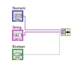
Now, the question is how to give different inputs to one single cluster. Let’s move to this portion. From the Function Palette, select Numeric Control, Boolean Control, and String Control. This is just to give an example of using different data elements of different types in one place. We can also use any other data type of our choice, like float double, special characters, etc. (refer to the figure below).

Block Diagram Connections
Connect each data type to the different blocks of the cluster through a wire, as shown in the figure below.
Now when we hover over the bundle by name block, we can see there are two connection pins left; whereas so far we have only discussed the input and output pins, what is the purpose of the remaining pins?

The second pin at the top tells the cluster about the content type of the data elements connected to it. Right-click on that pin, and from the drop-down menu, select Create and then select Constant. This creates a cluster constant having all the data types to which our corresponding bundle block is connected at the input side; see the figure below.
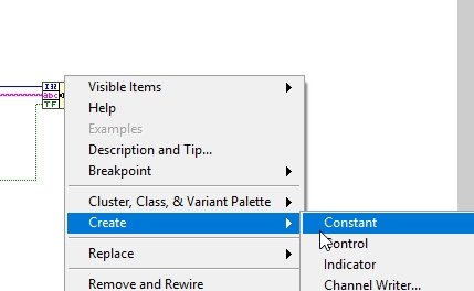
Constant Cluster
The resulting constant cluster block will appear. Connect this block to the upper pin of the bundle block, and the resulting block diagram will look like the one shown in the figure below.

This portion of the code is used for writing input data for the cluster. One may ask how to read the data at the output of the cluster after processing it as a single wire. For this purpose, again from the Function Palette, select Clusters, and then select Unbundle, as shown in the figure below.

The unbundle block has two inputs by default, and the block looks like the one shown in the figure below.

We can see that, as it is the output block, it does not have any constant pins at the top. Constant pin is only available on the bundle block, and you only have to declare the data type once, as we do for structures in other programming languages.
Size Adjustment Unbundle Cluster
The size of the unbundle block cannot be extended; however, if we connect the input side of the unbundle block to the output of the bundle block, it will automatically adjust the size of the unbundle block too according to its input and will also select the data types of all the portions of the cluster. Refer to the figure below.
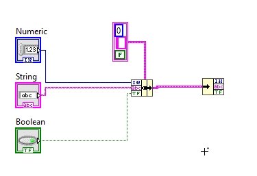
Now at any of the output pins of the unbundle block, right-click and create an indicator; it will result in the diagram shown in the figure below.

Do the same with the remaining two output pins of the unbundle block. Refer to the figure below to see the resulting block diagram.

The front panel of this block diagram is shown in the figure below.
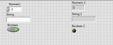
Lastly, we will set the desired values for the indicator. First, write a desired line in the string control and turn the Boolean button on. Now, run the program using the run button or by pressing <Ctrl+R>. Thus, the same value as that of the control will be displayed on the indicator in front.
This shows that through a single wire (between bundle and unbundle blocks), we can transmit as many data types as we want, as done in this tutorial. We can achieve the same functionality using bundle by name, which will bundle the elements according to their names but not their data types.
The figure below shows the output of the VI we designed in the tutorial.

Exercise
- Design a VI that does the same function as above, using bundle by name and unbundle-by-name blocks.
Conclusion
In conclusion, this tutorial provided a comprehensive overview of the cluster functions in LabVIEW. Starting with an introduction to clusters and their relationship with structures in other programming languages, the tutorial covered various examples and techniques to utilize cluster functions effectively. The use of bundle and unbundle blocks, along with the concept of constant clusters, is discussed in detail. The tutorial also encouraged readers to try the exercises and explore the bundle by name and unbundle by name blocks for further practice. Overall, this tutorial equips readers with the knowledge and skills to efficiently work with clusters in LabVIEW, enabling them to handle and manipulate different data types in a streamlined manner.
You may also like to read:
- Complete list of Labview tutorials and projects
- ESP32/ESP8266 Control Outputs with Web Server and Push Button Simultaneously
- acceleration measurement using Arduino Uno R3
- Reconnect ESP32 to WiFi after Lost Connection (Solved)
- Install Mosquitto MQTT Broker on Windows and Linux
- GPIO External Interrupts STM32 Nucleo with STM32CubeIDE
This concludes today’s article. If you face any issues or difficulties, let us know in the comment section below.