In this article, you will learn how to design a digital thermometer using a PIC microcontroller and MCP9700. You will learn how to interface MCP9700 with a PIC16F877A microcontroller and how to measure temperature using the MCP9700 low power voltage output temperature sensor. Before reading this article, you should have an idea of LCD interfacing with a PIC microcontroller and how to measure analog voltage using a PIC microcontroller. If you don’t know about them, I recommend you to read the following articles first. After reading the following article, you will be able to understand the circuit diagram and code of the MCP9700 based digital thermometer using a PIC microcontroller.
MCP9700 Temperature Sensor
The MCP9700 sensor converts temperature into voltage, which a microcontroller can easily measure. An analog-to-digital converter in the microcontroller reads the voltage. The microcontroller then converts the measured voltage back into temperature using mathematical manipulation in programming. The sensor can provide an accuracy of up to ±4°C and can measure temperatures ranging from -40°C to +125°C. It consumes only 6μA of operating current and can handle large capacitive loads.
- You may also like to read wireless temperature sensor using GSM.
MCP9700 Temperature Sensor Working
MCP9700 temperature sensor consists of a PN junction diode. The main temperature-sensing element is the PN junction diode. PN junction electrical characteristics contain a temperature coefficient that provides a change in voltage with a change in temperature. The change in voltage is scaled with a change in temperature according to the following steps per division:
1°C = 10mVMCP9700 interfacing with a microcontroller
The MCP9700-based digital thermometer does not require any external components. You do not need any signal conditioning circuit for it. You can directly interface it with the ADC of a microcontroller. In MCP9700, 1°C equals 10.0 mV. The general interfacing diagram of MCP9700 is as shown below:
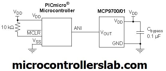
As shown in the above figure, the MCP9700 comes with a three-pin package. The three pins include the power supply pin, the ground pin, and the output voltage pin.
Circuit Diagram of MCP9700 Interfacing with PIC Microcontroller
The interfacing diagram with PIC microcontroller is shown below. PIC microcontroller interfaces with the LCD to display the temperature. The ADC measures the output voltage of the temperature sensor with the help of PIC16F877A microcontroller, as shown in the figure below:

Note: MCP9700 power supply pins are not shown in Proteus. By default, it is connected to the sensor. You should connect a 5-volt power supply to the temperature sensor.
Pic Microcontroller Code
The code for this project is written in the MIKROC compiler. It includes sections for reading the temperature, converting the data, and displaying it on the LCD. If you do not know how to use MikroC for Pic, you can refer to these tutorials:
- How to Use “MikroC PRO for PIC” to Program PIC Microcontrollers
- Pic microcontroller programming in c using Mikroc Pro for PIC
This code works with the MCP9700 temperature sensor and a PIC16F877A microcontroller to measure and display temperature in degrees Celsius.
The PIC16F877A microcontroller continuously reads the analog voltage from the MCP9700 temperature sensor, which is connected to one of the analog input channels of the PIC microcontroller’s ADC. The MCP9700 outputs a voltage that is linearly proportional to the temperature in degrees Celsius. The code then calculates the temperature value based on the ADC reading. If the ADC reading indicates a positive temperature, it displays a ‘+’ sign before the temperature value; otherwise, it displays a ‘-‘ sign for negative temperatures. It extracts the individual digits of the temperature, converts them to ASCII characters, and updates the LCD to display the temperature reading.
// Define LCD control pins and their directions
sbit LCD_RS at RB2_bit;
sbit LCD_EN at RB3_bit;
sbit LCD_D4 at RB4_bit;
sbit LCD_D5 at RB5_bit;
sbit LCD_D6 at RB6_bit;
sbit LCD_D7 at RB7_bit;

sbit LCD_RS_Direction at TRISB2_bit;
sbit LCD_EN_Direction at TRISB3_bit;
sbit LCD_D4_Direction at TRISB4_bit;
sbit LCD_D5_Direction at TRISB5_bit;
sbit LCD_D6_Direction at TRISB6_bit;
sbit LCD_D7_Direction at TRISB7_bit;

void main() {
    unsigned long int Temp;
    unsigned int ADRead;
    unsigned int vDisp[3];
    unsigned char Display[7];

    // Initialize port configurations
    PORTA = 0;
    TRISA = 0x01;
    PORTB = 0;
    TRISB = 0;

    // Initialize the LCD display
    LCD_Init();
    LCD_Cmd(_LCD_CURSOR_OFF);
    LCD_Cmd(_LCD_CLEAR);
    LCD_Out(1, 1, "Temp:");

    // Prepare the temperature display string
    Display[4] = 39; // ASCII code for the single quote (')
    Display[5] = 'C';

    // Configure the ADC
    ADCON1 = 0x0E;
    ADC_Init();

    while (1) {
        // Read the ADC value
        ADRead = ADC_Get_Sample(0);

        if (ADRead > 102) { // If temperature is positive
            Temp = (100 * ((10 * ADRead) - 1024)) >> 11; // Get temperature
            Display[0] = '+';
        } else { // If temperature is negative
            Temp = ((1024 - (10 * ADRead)) * 100) >> 11; // Get temperature
            Display[0] = '-';
        }

        // Extract individual digits of temperature
        vDisp[0] = Temp / 100;
        vDisp[1] = (Temp / 10) % 10;
        vDisp[2] = Temp % 10;

        // Convert digits to ASCII characters
        Display[1] = vDisp[0] + 48;
        Display[2] = vDisp[1] + 48;
        Display[3] = vDisp[2] + 48;

        // Display the temperature on the LCD
        LCD_Out(1, 8, Display);
    }
}
How this Code Works?
// Define LCD control pins and their directions
sbit LCD_RS at RB2_bit;
sbit LCD_EN at RB3_bit;
sbit LCD_D4 at RB4_bit;
sbit LCD_D5 at RB5_bit;
sbit LCD_D6 at RB6_bit;
sbit LCD_D7 at RB7_bit;

sbit LCD_RS_Direction at TRISB2_bit;
sbit LCD_EN_Direction at TRISB3_bit;
sbit LCD_D4_Direction at TRISB4_bit;
sbit LCD_D5_Direction at TRISB5_bit;
sbit LCD_D6_Direction at TRISB6_bit;
sbit LCD_D7_Direction at TRISB7_bit;
These lines define the control pins for the LCD (Register Select, Enable, and Data pins) and their respective directions for input and output.
void main() {
    unsigned long int Temp;
    unsigned int ADRead;
    unsigned int vDisp[3];
    unsigned char Display[7];

    // Initialize port configurations
    PORTA = 0;
    TRISA = 0x01;
    PORTB = 0;
    TRISB = 0;

    // Initialize the LCD display
    LCD_Init();
    LCD_Cmd(_LCD_CURSOR_OFF);
    LCD_Cmd(_LCD_CLEAR);
    LCD_Out(1, 1, "Temp:");

    // Prepare the temperature display string
    Display[4] = 39; // ASCII code for the single quote (')
    Display[5] = 'C';

	// Configure the ADC
    ADCON1 = 0x0E;
    ADC_Init();

    while (1) {
        // Read the ADC value
        ADRead = ADC_Get_Sample(0);

        if (ADRead > 102) { // If temperature is positive
            Temp = (100 * ((10 * ADRead) - 1024)) >> 11; // Get temperature
            Display[0] = '+';
        } else { // If temperature is negative
            Temp = ((1024 - (10 * ADRead)) * 100) >> 11; // Get temperature
            Display[0] = '-';
        }

        // Extract individual digits of temperature
        vDisp[0] = Temp / 100;
        vDisp[1] = (Temp / 10) % 10;
        vDisp[2] = Temp % 10;

        // Convert digits to ASCII characters
        Display[1] = vDisp[0] + 48;
        Display[2] = vDisp[1] + 48;
        Display[3] = vDisp[2] + 48;

        // Display the temperature on the LCD
        LCD_Out(1, 8, Display);
    }
}
These lines demonstrate the main part of the code that implements the functionality of the digital thermometer.
- The function defines the main function and declares the necessary variables for temperature calculation and display.
- It initializes the port configurations for the microcontroller’s pins connected to the LCD display and analog temperature sensor.
- It initializes the LCD display, clears it, and displays the header “Temp:”.
- It prepares the temperature display string by assigning ASCII codes for single quote (39) and ‘C’ to Display[4] and Display[5], respectively.
- It configures the Analog-to-Digital Converter (ADC) for temperature sensing.
- Inside the infinite while loop, it reads the ADC value from the temperature sensor.
- Depending on the ADC value, it calculates the temperature and assigns it to the Temp variable. If the temperature is positive, it assigns ‘+’ to Display[0], otherwise it assigns ‘-‘.
- It extracts the individual digits of the temperature and assigns them to vDisp array elements.
- It converts the digits to ASCII characters and assigns them to Display array elements.
- Finally, it displays the temperature on the LCD at the desired position using the LCD_Out() function.
Conclusion
In conclusion, this article provided a comprehensive guide on designing a digital thermometer using a PIC microcontroller and the MCP9700 temperature sensor. The article covered various aspects such as the working principle of the MCP9700 sensor, its interfacing with a microcontroller, and the circuit diagram for the project. The code for the PIC16F877A microcontroller was also discussed in detail, explaining how it reads the temperature from the sensor and displays it on an LCD screen. By following this article, readers can gain a solid understanding of how to implement a digital thermometer using these components. With the ability to measure temperature accurately, this project opens up possibilities for a wide range of applications in various fields.
Related content:
- MPU6050 Sensor Module Interfacing with Pic Microcontroller
- DHT22 Temperature and Humidity Sensor Interfacing with Pic Microcontroller
- LM35 Temperature Sensor with 7-Segment Display using Pic Microcontroller
- Line Tracking Module interfacing with pic microcontroller
- Infrared Obstacles Avoidance Sensor Module interfacing with pic microcontroller
- RFID reader RDM630 interfacing with pic microcontroller