In this tutorial, we will learn how to use the input and output ports of the 8051 microcontroller. The 8051 microcontroller has 40 pins, comprising four I/O ports. The microcontroller uses 8 pins for specific purposes, while 32 pins are configurable as input and output pins to connect the microcontroller with peripheral devices. Each port consists of 8 bits, which we can define as an input or an output. In this article, we will discuss how to use the I/O ports of the 8051 microcontrollers so that we can use them for read and write purposes.
Before reading this article further, you should know how to program the 8051 microcontroller with KEIL.
GPIO Pins 8051 Microcontroller
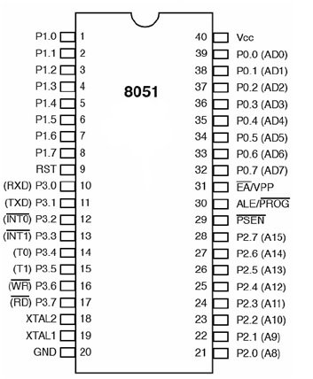
8051 GPIO Ports details
A port is usually a set of eight pins, and we call them I/O because we can configure them as input or output. 8051s has four GPIO ports, and each port has eight pins; each pin may have one or more than one function. We will see them one by one.
PORT 0 – 8051 Microcontroller
Now let’s have a look at Port 0, which is an open-drain bi-directional I/O port. Open drain simply means a transistor that connects to the Ground, while bi-directional refers to the fact that this PORT is configurable as an input or an output. We can use the P0 register to access PORT 0. This register is a bit accessible. Bit accessible means that we can access individual bits of the register. For example, writing 1 to some bit of the P0 register will configure the corresponding pin as input, while writing 0 will configure that pin as output. By default, the microcontroller configures every pin as input when it turns on.
P0 Register Pins
P0 includes pins (32–39). It is an I/O port with some alternative functions.
- When a microcontroller utilizes external memory, it must communicate with this memory using special pins and send a lower address byte to the external memory using P0 pins. If no external memory is connected, the microcontroller can use all P0 pins for I/O tasks.
- P0 pins don’t have a built-in pull-up resistor.
- If we configure p0 as an input, it behaves as if it is “floating”. This means its input resistance is very high, and its potential becomes uncertain because it is not actively driven by any source.
- When we set the P0 pin of the microcontroller as output, it behaves like an “open drain”. If we set the logic to 0, the pin connects to the ground (0 V). But if we provide the P0 pin with logic 1, it behaves as “floating”. In order to keep a stable logic voltage of 5 V, we need to connect an external pull-up resistor.
Sample Command
Let’s write some simple code for testing Port 0. We will configure the lower four bits of PORT0 as input and the upper four bits as output, and whatever input we apply to the lower four bits should appear on the upper four bits. For configuring any pin of P0 as input, we write 1 to the corresponding bit of the P0 register. In our case, we have to configure the lower four bits as inputs to P0, so we will write 1 to power the four bits. Now that we have configured the upper four pins of P0 as outputs, we will write 0 to all four upper bits of the P0 register; in hexadecimal, it will become 0x0F.
P0=0X0F;PORT 1 – 8051 Microcontroller
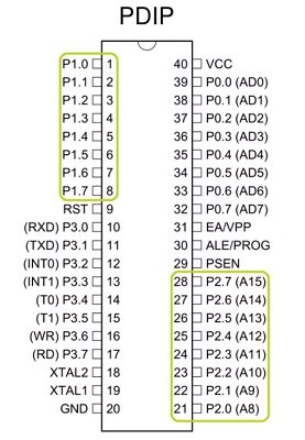
P1 includes pins (1–8). It is an I/O port with no alternative functions and is configurable only for general I/O purposes. P1 contains a built-in pull-up resistor and is compatible with TTL circuits.
PORT 2 – 8051 Microcontroller
P2 includes pins (21-28). It is an I/O port with the same alternative functions as port 0. When we use the external memory with the microcontroller, then we apply the higher address byte (addresses A8–A15) on P2. When there is no external memory, all bits of P0 are configurable for I/O purposes.
Port 1 and Port 2 are 8 bits each, bi-directional, and have internal pull-up resistors. This means that there is no need for any external pull-up resistors for both Port 1 and Port 2. Writing 1 to each bit of a port configures that port as input while writing zero configures that port as output. By default, the microcontroller configures both ports as inputs when it turns on.
Configure Port 1 and 2 of 8051
Now we are going to see Port 1 and Port 2 with interesting and simple examples. We will make a simple program that will configure Port 1 as input and Port 2 as output, and whatever input we apply to Port 1 will be sent to Port 2. Let’s try to code this example. We can write 0xFF to Port 1 to configure it as input, and we can also skip this step as the microcontroller already configures Port 1 as input by default as it powers on. We can also configure Port 2 as an output by writing 0 to it.
void main()
{
  P1 = 0xFF;
  P2 = 0x00;

  while (1) {
    P2 = P1;
  }
}
In this code, we have set Port 1 as input by writing P1 = 0xFF, and then we have set Port 2 as output using 0x00. In the last part, we want to send Port 1’s input to Port 2, so we can simply put Port 2 equal to Port 1.
PORT 3 of 8051 Microcontroller
P3 includes pins (10–17). It is an I/O port with an alternative function. For using the alternative functions, a logic one (1) must be applied to the appropriate bit of the P3 register. In terms of hardware, this port is similar to P0, but it contains a built-in pull-up resistor, which is not present in P0.
Pin Configuration Setting – Input/output Ports 8051 Microcontroller
The pin configurations are shown in the table below:
| Pin configuration | Working |
|---|---|
| Input | Pin needs to be configured as 1 for input. |
| Output | Pin needs to be configured as 0 for output. |
Note: By default, all the pins are configured as inputs when the microcontroller is powered on.
Current Limitation of Pins
When assigning the Ports or individual pins as input or output, we must be careful about their current limitations; Otherwise, it can damage the microcontroller. We have discussed these limitations below:
- When we configure a pin as an output, a single pin can receive a current of 10 mA. If we configure the pin as an input, the built-in pull-up resistors provide very weak current but can handle up to 4 TTL inputs.
- If all 8 bits of a port are active, then the limit of total current must be 15 mA. But for port 0, it can be up to 26 mA (port P0: 26 mA).
- If all four ports (32 bits) are active, then the total current must be limited to 71 mA.
Proteus Simulation
We have provided the Proteus simulation of the blink example. In this simulation, the program is written in C language with KEIL IDE software. We add the hex file to the 8051 microcontroller via properties. The Input to the microcontroller is given through the push button, and the output can be seen by a glowing LED.
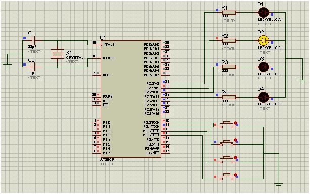
Now, we will explain how this schematic works. When we press the first button, the first LED (D1) will glow. This LED will keep glowing for 1 second, and then it will turn off. If we press the 2nd or 3rd button, then the D2 or D3 LED will turn on for 1 second, respectively.
Note: The crystal oscillator’s frequency needs to be set at 11.059 MHz for proper operation.
8051 LED Blinking Example
In this section, we have provided the code that was used for the Proteus simulation in the previous section.
#include<reg51.h>

sbit Led1 = P2 ^ 0; //Defining LED Pins
sbit Led2 = P2 ^ 1;
sbit Led3 = P2 ^ 2;
sbit Led4 = P2 ^ 3;

sbit Button1 = P3 ^ 0; //Defining Button Pins
sbit Button2 = P3 ^ 1;
sbit Button3 = P3 ^ 2;
sbit Button4 = P3 ^ 3;

void Delay(int); //Delay function declaration

int main()
{
  P2 = 0x00; //used as output port
  P3 = 0xFF; //used as input port

  do
  {
    if (Button1 == 0) //If 1st switch pressed
    {
      Led1 = 1; //1st LED ON
      Delay(1000);
      Led1 = 0; //LED OFF
    }
    if (Button2 == 0) //If 2nd switch pressed
    {
      Led2 = 1; //2nd LED ON
      Delay(1000);
      Led2 = 0;
    }
    if (Button3 == 0) //If 3rdswitch pressed
    {
      Led3 = 1; //3rd LED ON
      Delay(1000); //Delay
      Led3 = 0; //LED OFF
    }
    if (Button4 == 0) //If 4thswitch pressed
    {
      Led4 = 1; //4th LED ON
      Delay(1000); //Delay
      Led4 = 0; //LED OFF
    }
  }

  while (1);
}

void Delay(int k)
{
  int j;
  int i;

  for (i = 0; i < k; i++)
  {
    for (j = 0; j < 100; j++)
    {

    }
  }
}
Code Explanation
Now, we will explain in detail how each part of the code works.
#include<reg51.h>First, we include the header file for registers on the 8051 microcontroller. This will help us when dealing with Ports and registers.
sbit Led1 = P2 ^ 0; //Defining LED Pins
sbit Led2 = P2 ^ 1;
sbit Led3 = P2 ^ 2;
sbit Led4 = P2 ^ 3;

sbit Button1 = P3 ^ 0; //Defining Button Pins
sbit Button2 = P3 ^ 1;
sbit Button3 = P3 ^ 2;
sbit Button4 = P3 ^ 3;
Then we define the LED pins for Port 2 and the button pins for Port 3.
void Delay(int); //Delay function declaration

int main()
{
  P2 = 0x00; //used as output port
  P3 = 0xFF; //used as input port
Now, we define a function by the name of delay. This function adds a delay of 1 second between the on and off states of the LED. Further, we will show how this delay works. We have set Port 2 as output and Port 3 as input. We will initialize these Ports as 0 (to write) and 1 (to read), respectively.
do
  {
    if (Button1 == 0) //If 1st switch pressed
    {
      Led1 = 1; //1st LED ON
      Delay(1000);
      Led1 = 0; //LED OFF
    }
    if (Button2 == 0) //If 2nd switch pressed
    {
      Led2 = 1; //2nd LED ON
      Delay(1000);
      Led2 = 0;
    }
    if (Button3 == 0) //If 3rdswitch pressed
    {
      Led3 = 1; //3rd LED ON
      Delay(1000); //Delay
      Led3 = 0; //LED OFF
    }
    if (Button4 == 0) //If 4thswitch pressed
    {
      Led4 = 1; //4th LED ON
      Delay(1000); //Delay
      Led4 = 0; //LED OFF
    }
  }

  while (1);
}
In this part of the code, we check whether a button is pressed. If any button is pressed, then the code goes to the corresponding case. For example, if we press button 3, then the code moves to the if statement of Button 3. We check these cases continuously by using a while loop.
void Delay(int k)
{
  int j;
  int i;

  for (i = 0; i < k; i++)
  {
    for (j = 0; j < 100; j++)
    {

    }
  }
}
The Delay function takes an argument, which we have set to 1000 in the cases above. For delays, a nested loop structure is useful as it keeps the microcontroller occupied until the iterations are complete. This way, we get a whole second delay between the LED on and off commands.
Video Demonstration
Conclusion
In this article, we have covered the following topics:
- What are the Input/output Ports of 8051 Microcontroller.
- Working of Port 0 – Port 3.
- Schematic Diagram.
- Sketch and explanation.
Related Articles:
If you want to read similar articles, check out the links below:
- How to download and install KEIL uVision for ARM and 8051
- 8051 Microcontroller tutorials in c programming examples
- serial communication 8051 microcontroller using keil
- servo motor interfacing with 8051 using keil compiler
- Interface LCD with 8051 Microcontroller
- KEYPAD INTERFACING 8051 MICROCONTROLLER with code
This is all about how to use the input/output ports of the 8051 microcontroller. These I/O ports can connect to the following modules: LED matrix, dc motor driver, seven segment display, and LCD. There are many more applications of input/output ports of the 8051 microcontroller.
Your above project are become very useful for me
so, thankyu very much.
What has to change in code if we want to use only 3 buttons and 4 LEDs
so the 4th LED will be on only if Button2 & Button3 are both pressed???
Any idea how we can do this in assembly language?