Overview of Data Acquisition System: Data acquisition is the process of automatically obtaining data from one or more sensors or transducers directly into the computer system. A sensor is a device that responds to a physical change and outputs an electrical signal, and a transducer is a device that converts energy from one form to another. For example, a thermocouple generates an electromotive force (emf) due to two dissimilar metals joined at its junction. The generated emf is a low-level voltage. When this voltage is sent to a wire, it is called a voltage signal. A transducer can be used to convert the low-level voltage signal to a high-level voltage signal.
We have already posted an article on how to get data serially on Labview, which is an example of a Data Acquisition system.
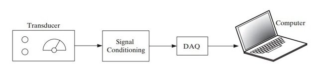
Components of Data Acquisition System
A simple system consists of
- Transducer
- Data Acquisition Hardware (DAQ)
- Computer
Once the sensor outputs a signal that can be transmitted to a wire, there are still cases when there could be a mismatch in terms of the type and range of the signal and the type and range of the data acquisition hardware. For example:
- Some transducers might be designed to generate a current signal as output but our data acquisition hardware could have been designed to take a voltage signal as input.
- A transducer might be designed to give output voltage in the range of 50-100mV but our data acquisition hardware accepts the input voltage signal in the range of 0-10V.
Signal conditioning may be required to adjust the signal type and range of the output signal to align with the requirements of the data acquisition system. Once mismatches between transducers and data acquisition hardware are removed, data can be collected.
The computer needs to know
- Which signal to measure
- How often to take readings
- How many readings to collect or how long to continue reading the signal.
This is known as configuring the data acquisition process and is done before collecting the data.
The ability of LabVIEW to take in data from an external source, process it, and send processed data back to control external devices is what distinguishes LabVIEW from other software. The collected data is called a waveform in LabVIEW. This data can be displayed, analyzed, modified, or stored.
Sensor and Transducer
The bottom line when it comes to measuring a variable of interest is identifying some physical phenomenon that changes when the variable of interest changes. For example, the volume of a fluid expands as its temperature increases, and that physical phenomenon has been utilized to create thermometers. While lots of physical phenomena have been used for measurements, phenomena that can be related to an electrical property are more useful for automated data acquisition systems. A sensor is a device that responds to a physical change and outputs an electrical signal and a transducer is a device that converts energy from one form to another.
Signal Conditioning
The process of modifying the output of a sensor is called signal conditioning. Signal conditioning is required for the following reasons.
- Dealing with noisy signal (filtering)
If the signal is noisy, the gauge needle bounces around while taking a reading. Signal noise is very common. The sources of signal noise include the system itself, and sometimes noise is also created by the electronic sensor itself. We can deal with signal noise in the following ways:
- Modifying the system
- Using better quality sensor
- Ignoring the noise
- Using a bunch of readings so that result can be averaged
- Filtering the system before it gets into the data acquisition system
- Filtering the signal after the data acquisition system
- Aligning sensor output with DAQ (Amplification and offset)
When the range of a sensor’s signal differs from the input range of the data acquisition system, signal conditioning can be used to rescale the signal from the sensor. Common modifications include amplification and offset. Amplification increases the span, while adjusting the offset increases or decreases all values in the span by the same amount.
Sensor Calibration
Sometimes there is an equation relating a sensor’s output to the measured variable. For example, the temperature at the junction of a thermocouple can be calculated if the voltage is known. If you use signal conditioning to adjust the range of the sensor output signal, you must account for the offset and amplification values to determine the measured value from the sensor output. This is extremely important when the sensor output signal must be related to an external standard.
Data Acquisition Hardware
Data acquisition devices are a bridge between sensors and computer systems. When considering which data acquisition system to use, there are several things to consider.
- What types of signals will the data acquisition system need to handle?
- How many AI channels (analog inputs) are required
- How many AO channels (analog outputs) are required
- How many DI channels (digital inputs) are required
- How many DO channels (digital outputs) are required
- Will your AI channels be wired as differential inputs or single-ended?
- What level of precision is required in the analog-to-digital converter?
- How fast will you need to take samples?
Differential Inputs
When AIs are wired as differential inputs, the two signal wires are connected to two AI channels that are configured to work together to measure the voltage difference between the two wires.
Single-Ended Inputs
Single-ended inputs only require one AI channel per measurement and can work under the right conditions.
Analog to Digital Converters
Once the signal passes through the AI port, it must be converted to a digital value corresponding to the signal voltage. An ADC performs this action. One of the characteristics of an ADC is the number of bits used to describe the voltage level. The higher the bit count, the greater the resolution of the ADC. Common ADCs are 12–22 bit devices.
You can find about different types of ADCs in the following articles:
- Successive Approximation ADC – Analog to Digital Converter
- Single Slope and Dual Slope ADC – Integrating Analog to Digital Converter
- Counter Type ADC – Staircase Approximation Analog to Digital Converter
- Tracking Type ADC – Up/Down Counter Analog to Digital Converter
Sampling Rate
Another consideration when selecting a data acquisition system is the required sampling rate. The analog-to-digital conversion process takes a finite amount of time. If you want to take one sample a second, any data acquisition system will work fine. If you need to sample each of 32 AI channels at 1000 samples a second (total of 32,000 samples/second), that is a tougher challenge but there are data acquisition systems that can handle it.
How Does Data Acquisition System Work?
A data acquisition system is composed of several key components and follows a specific working process. Here is an overview of how a data acquisition system works:
- Sensors and Transducers: The process begins with sensors and transducers that respond to physical changes and convert them into electrical signals. These signals can represent parameters such as temperature, pressure, humidity, voltage, current, and more.
- Signal Conditioning: In some cases, the output signal from the sensor may need to be adjusted or modified before it can be accurately measured by the data acquisition system. This process, known as signal conditioning, involves tasks such as noise filtering, amplification, offset adjustment, and aligning the signal range with the input range of the data acquisition system.
- Data Acquisition Hardware (DAQ): The conditioned signals are then sent to the data acquisition hardware, which acts as a bridge between the sensors and the computer system. The DAQ hardware converts the analog signals into digital form using an analog-to-digital converter (ADC). The ADC measures the voltage level of the analog signal and represents it as a digital value.
- Computer Interface: The digitized data is transmitted to the computer through a communication interface, such as USB, Ethernet, or PCI. The interface allows the computer to receive the data from the data acquisition hardware for further processing and analysis.
- Configuring the Data Acquisition Process: Before data collection begins, the computer needs to be configured with specific parameters, such as which signals to measure, the sampling rate (how often to take readings), the duration of data collection, and other relevant settings. This configuration step ensures that the data acquisition system collects the desired information accurately and efficiently.
- Data Collection: Once the data acquisition system is properly configured, it starts collecting the data according to the specified parameters. The data acquisition hardware continuously samples the analog signals at the defined sampling rate and converts them into digital values.
- Data Storage and Processing: The collected data is sent to the computer, where it can be stored and processed. The data can be visualized, analyzed, modified, or stored in various file formats for further use. This step may involve using specialized software, such as LabVIEW, to perform data analysis and generate insights from the collected data.
- Data Presentation: The processed data can be presented in various graphical or tabular formats, depending on the requirements of the application. It can be displayed in real-time or saved for later analysis and comparison.
This is a general overview of how a data acquisition system works. The specific details may vary depending on the design and functionality of the system, as well as the requirements of the application in which it is used.
Applications
Data acquisition systems find applications in various fields that require the collection, measurement, and analysis of data. Here are some common applications of data acquisition systems:
- Scientific Research: Data acquisition systems are extensively used in scientific research to collect data from sensors and transducers. They enable researchers to monitor and analyze various parameters in real-time, such as temperature, pressure, humidity, voltage, current, and more.
- Industrial Process Monitoring and Control: Data acquisition systems play a vital role in industrial automation and control. They are used to monitor and control parameters like temperature, flow rate, pressure, and level in manufacturing processes. This helps maintain optimal conditions, ensure quality control, and improve overall efficiency.
- Environmental Monitoring: Data acquisition systems are employed in environmental monitoring applications to gather information about air quality, water quality, weather conditions, and other environmental factors. This data is crucial for studying and managing ecosystems, detecting pollution, and making informed decisions about conservation efforts.
- Automotive Testing: In the automotive industry, data acquisition systems are used for performance testing, durability testing, and emissions testing of vehicles. They capture data from various sensors installed in vehicles to analyze factors like speed, acceleration, engine performance, and fuel efficiency.
- Biomedical Research: Data acquisition systems are employed in biomedical research to collect physiological data from patients or experimental subjects. This includes monitoring vital signs, brain activity, muscle activity, and other physiological parameters. This data aids in the diagnosis, treatment, and understanding of various medical conditions.
- Energy Monitoring: Data acquisition systems help monitor energy consumption in buildings, factories, and power plants. By collecting data on electricity usage, heat generation, and other energy-related parameters, these systems enable energy auditing, optimization, and conservation efforts.
- Home Automation: Data acquisition systems are used in smart homes to monitor and control various aspects of the living environment. They collect data from sensors like motion detectors, temperature sensors, and light sensors to automate tasks such as lighting control, security monitoring, and energy management.
These are just a few examples of the wide-ranging applications of data acquisition systems. With their ability to collect, process, and analyze data in real-time, these systems have become indispensable tools in many fields.
My name Is Efraim from Namibia. I would like to major in SCADA and this Data Acquisition system basics and working topic sounds interesting. Have you built this project yet.?
Regards,
yes i did money you can contact me at microcontrollerslabhub@gmail.com to discuss your project
Many thanks for this useful introduction