In this tutorial, we will learn how to use ESP32 dual-core using FreeRTOS and Arduino IDE. The ESP32 development board consists of 2 Xtensa 32-bit LX6 microprocessors which makes it a dual-core microcontroller. This core0 and core1 are included for better performance and efficiency. When programming ESP32 using Arduino IDE, by default core1 is used and core0 is used for RF communication. To run the program code on core0, some additional steps have to be followed. This article deals with successfully programming ESP32 on both the cores simultaneously using Arduino IDE.
Recommended Components
The following components are used in this project or are helpful for building it with the ESP32.
| Component | How it’s used in this project | Buy on Amazon |
|---|---|---|
| ESP32 Development Board (DevKit V1) | The dual-core board running both FreeRTOS tasks, one pinned to core0 and one to core1. | Check Price |
| Micro USB Cable | Connects the ESP32 to your computer to upload the sketch and view core IDs on the serial monitor. | Check Price |
| Breadboard | Holds the ESP32 and two LEDs for the dual-core blink demo without soldering. | Check Price |
| Jumper Wires | Wire the LEDs from GPIO32 and GPIO25 to ground through the current-limiting resistors. | Check Price |
As an Amazon Associate we earn from qualifying purchases. Prices and availability are accurate as of the date/time indicated and are subject to change.
Prerequisites
We will use Arduino IDE to program our ESP32 development board. Therefore, you should have the latest version of Arduino IDE. Additionally, you also need to install the ESP32 plugin in Arduino IDE. If your IDE does not have the plugin installed you can visit the link below:
Installing ESP32 library in Arduino IDE and upload code
When you install the ESP32 add-on in Arduino IDE, FreeRTOS library will be installed by default.
ESP32 Dual Core Introduction
As mentioned before, the ESP32 module consists of two powerful 32-bit microprocessors which make it a dual-core chip. Below we have attached the functional block diagram of the ESP32 board found in its datasheet by Espressif. You can view the datasheet by accessing the link here.
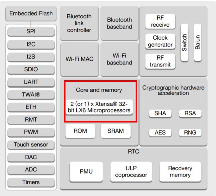
You can clearly see it highlighted in red: the Core and memory block of the ESP32 module. It consists of either single or double 32-bit microprocessors. The price is almost the same so the dual-core module is purchased more because of the obvious advantages.
Dual-core vs Single-core
The main advantage of having a dual-core process is that we can execute two tasks concurrently or in parallel.
- Able to run more than one task at the same time with the help of dual cores instead of a single core
- Less tasks exeuction time leads to run more task as a single gets distributed among the two cores
- When a core is not being used, it can be used to turn off the peripherals that are not needed. This leads to reduced power consumption.
Although ESP32 has two cores such as protocol core (CPU0) and application core (CPU1). Both these cores are of Xtensa 32-bit LX6 architecture and share the bus to access memory and other peripherals. Protocol core (CPU0) in ESP32 is used to run various wireless protocols stacks such as WiFi, Bluetooth, and BLE. On the other hand, the application core (CPU1) is used to run application programs separate from the networking layer. If you have a critical application using Bluetooth and WiFi, it is recommended to use CPU1 or application core only for user applications.
FreeRTOS Introduction
Unlike typical real-time operating systems, FreeRTOS is specially designed for microcontrollers. Because Microcontrollers come with limited resources, therefore, we need an operating system as per the available resources of microcontrollers. It is an open-source Kernel that means it can download free of cost and be used in RTOS-based applications. Although, it has two commercial variants also such as OpenRTOS and SafeRTOS.
As we mentioned earlier, by using FreeRTOS, we can make sure that each task of Arduino will have a deterministic execution pattern and every task will meet its execution deadline. In other words, it is a scheduler that assigns Arduino CPU resources to every task according to a scheduling algorithm. The real-time operating system has different scheduling algorithms such as:
- Difference Between Preemptive and Non-Preemptive Scheduling
- What is a Scheduling Algorithm
- Rate Monotonic Scheduling
- Earliest Deadline First
- Least Laxity First
FreeRTOS Features
Followings are the main kernel features:
- Fixed Priority Preemptive Time slicing Scheduler
- Inter-Process Communication through Queues
- Tasks Management such as Task priority setting, task suspension, task deletion, and Task delay
- Tasks Synchronization with Gatekeeper Tasks, Semaphore, and Mutex
- Timing measurement hook
- Run time Tracing hooks
- Software timers management
- Interrupt management
For more information on FreeRTOS read here:
How to use FreeRTOS with Arduino – Real-time operating system
Arduino Sketch to find on which ESP32 Core Programming is Running?
As we mentioned before, when we upload code to ESP32 Arduino IDE, the program runs on the ESP32 core1 by default. As with all the ESP32 projects which we have uploaded to date, the program runs only on core1. In order to know which core is being used for respective tasks, you can use the xPortGetCoreID() function. It will identify the core ID on which the core is running. We will use the following function to know this:
xPortGetCoreID()You can call this function separately in the setup() and loop() functions to know the core IDs for the respective functions.
Open your Arduino IDE and go to File > New. A new file will open. Copy the code given below in that file and save it.
void setup() {
  Serial.begin(115200);
  Serial.print("setup() is running on core ");
  Serial.println(xPortGetCoreID());
}

void loop() {
  Serial.print("loop() is running on core ");
  Serial.println(xPortGetCoreID());
}
Choose the correct board and COM port before uploading your code to the board. Go to Tools > Board and select ESP32 Dev Module.
Next, go to Tools > Port and select the appropriate port through which your board is connected.
Click on the upload button to upload the code into the ESP32 development board.
After you have uploaded your code to the development board, press its ENABLE button.

Open the serial monitor and you will be able to view the messages which will depict that core1 is being used to run both the functions.
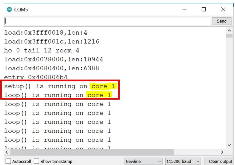
Thus, it can be seen that, by default, the program code will always run on core1. To be able to use both the cores we will have to use some additional steps.
FreeRTOS Create Tasks
As discussed earlier, Arduino IDE provides a FreeRTOS library for ESP32. The FreeRTOS permits us to run multiple tasks on a single core or on multiple cores. For example, we can run a group of tasks on core0 and another group of tasks on core1 of ESP32.
Create Task to run on any Core
First, let’s see how to create a Task in FreeRTOS and after that, we will see how to create a task that will be pinned to a specific core.
xCreateTask() function is used to create tasks and adds them to the ready queue for execution. It takes 5 arguments as inputs to define various features of the task.
xTaskCreate(MyTask_pointer, "task_name", 100, Parameter, Priority, TaskHandle);
Pointer to Task Function
MyTask_pointer: This first argument to task creation function is a pointer to a function definition of a task. Because we need to define a task with the help function. We will see later how to define a function and pass this pointer to a function as an argument.
task_name: This argument is just the name of the function/task that we will create.
Stack Size
StackDepth: In multitasking, each task/thread has its own stack. It defines the stack size of a task in bytes. Therefore, you should make sure to select stack size according to the complexity of computation. For instance, we select 100 bytes size in this example.
Parameter: If we want to pass a pointer to a variable as an argument to the task function, we can use this argument. Otherwise, we can pass the NULL value. This argument is a pointer to a variable that the task (function) can receive.
How to set Priority ?
Priority: This is an important parameter because it is used to set the priority of tasks. We set priority with passing numbers as an argument. For example, if we create four tasks and assign them priority 0, 1,2, and 3. Hence, zero means the lowest priority, and 3 means the highest priority.
TaskHandle: This argument keeps the handle of the function that we can use to change function features such as the deletion of a task, changing its priority, etc.
Using ESP32 core0 and core1: Creating Tasks
We will show you how to use ESP32 core0 and core1 to run tasks simultaneously. We aim to blink an LED after every 0.5 seconds in core0 and another LED after every 1 second in core1. For that purpose, we will use the Arduino IDE. The ESP32 development board comes with FreeRTOS firmware already installed on it which is supported by the Arduino IDE as well. The FreeRTOS is a Real-time Operating System used to run multiple tasks individually. This firmware allows the ESP32 board to multitask via API functions. We will use these functions to create separate tasks that will be run on different cores.
Now, we will show you some steps which need to be followed to make sure certain parts of the code run on different cores. For that purpose, we will create tasks. When creating a task we can specify the core in which that particular task will run and can also set its priority to run.
Defining Task Handle
Firstly, we will define the task handle. As we want to run two separate tasks on different cores hence we will define the task handle as follows:
TaskHandle_t Task1;
TaskHandle_t Task2;
Creating Task
Secondly, in the setup() function we will use xTaskCreatePinnedToCore() function to create the task for core0 and core1 respectively. This function takes in seven parameters. They are listed in order below:
- The first parameter is the name of the function that will implement the task e.g. Task1code or Task2code.
- The second parameter is the name that we will allot to the task e.g. Task1 or Task2.
- Next, is the stack size that is given to the task e.g. 10000.
- This is the task input parameter.
- The priority of the specified task comes next where 0 signifies the lowest priority.
- The sixth parameter is the task handle which we previously defined e.g. &Task1 or &Task2
- Lastly, we will specify the core ID where that particular task will be run e.g. 0 or 1 where 0 is core0 and 1 is core1.
Here, we are creating the task for Task1 set at the highest priority which will run in core0.
xTaskCreatePinnedToCore(Task1code,"Task1",10000,NULL,1,&Task1,0); Here, we are creating the task for Task2 set at the highest priority which will run in core1.
xTaskCreatePinnedToCore(Task2code,"Task2",10000,NULL,1,&Task2,1); Defining Task Function
Thirdly, we will create the Task1code and the Task2code function. These functions will do their respective jobs of blinking the LED at the set time.
For Task1 we want the LED to blink after every 0.5 seconds. This function takes in a single global argument called a parameter. First, we will display on the serial monitor the core ID on which the particular task is running. Next, we will use for(;;) to create an infinite loop where the LED will be toggled after every 0.5 seconds. This will be achieved by using the digitalWrite() function and passing the GPIO pin connected with the first LED and ‘HIGH’ or ‘LOW’ as the second parameter.
void Task1code( void * parameter ){
  Serial.print("Task1 running on core ");
  Serial.println(xPortGetCoreID());

  for(;;){
    digitalWrite(led_1, HIGH);
    delay(500);
    digitalWrite(led_1, LOW);
    delay(500);
  }
}
Similarly, for Task2 we want to blink the LED after every 1 second.
void Task2code( void * pvParameters ){
  Serial.print("Task2 running on core ");
  Serial.println(xPortGetCoreID());

  for(;;){
    digitalWrite(led_2, HIGH);
    delay(1000);
    digitalWrite(led_2, LOW);
    delay(1000);
  }
}
Additionally, if you want to delete any created task use the following function and specify the task handle as a parameter inside it.
vTaskDelete(taskHandle);Simple Project using ESP32 dual-core
After learning all the techniques mentioned previously, now we will demonstrate our simple project.
The following components are required:
- ESP32 development board
- Two 5mm LED
- Two 220 ohm resistor
- Breadboard
- Connecting Wires
Schematic Diagram
Assemble your circuit as shown in the diagram below:
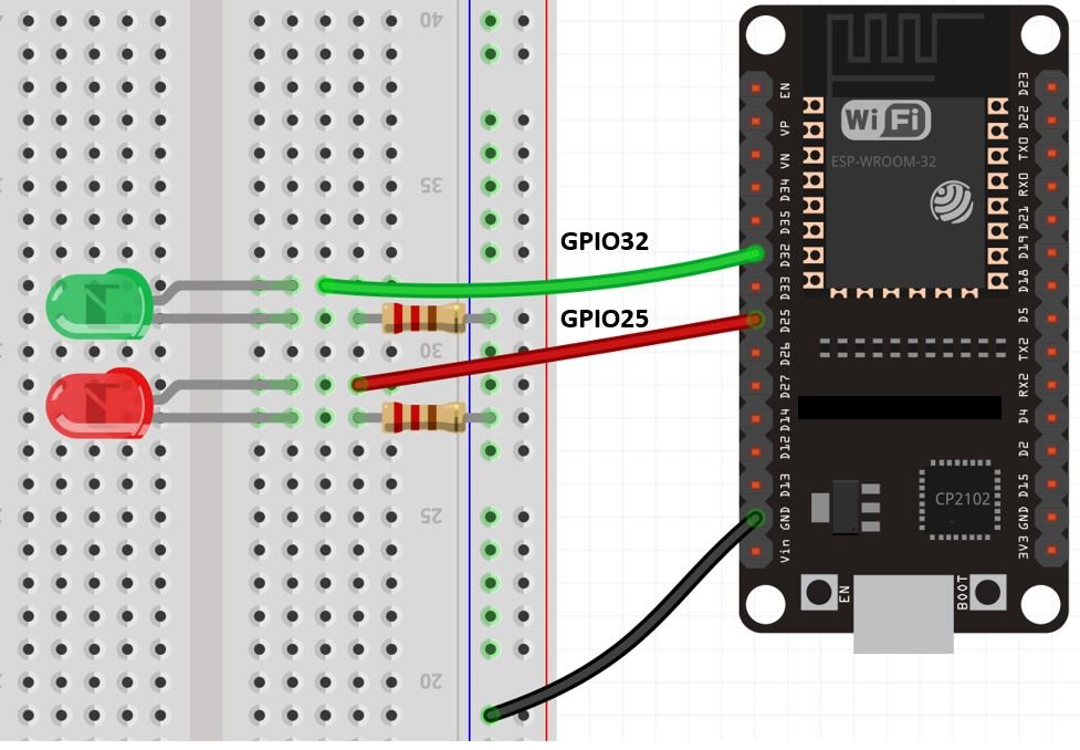
Connect the LED anodes with the ESP32 GPIO Pins. We are using GPIO32 and GPIO25 for this project. Also, make sure to connect the cathode terminals of the LEDs with the ground pin of the ESP32 board through a 220-ohm current limiting resistor. You can use any appropriate output GPIO pins.
Arduino Sketch
Open your Arduino IDE and go to File > New. A new file will open. Copy the code given below in that file and save it.
TaskHandle_t Task1;
TaskHandle_t Task2;

const int led_1 = 32;
const int led_2 = 25;

void setup() {
  Serial.begin(115200);
  pinMode(led_1, OUTPUT);
  pinMode(led_2, OUTPUT);

  xTaskCreatePinnedToCore(Task1code,"Task1",10000,NULL,1,&Task1,0);
  delay(500);

  xTaskCreatePinnedToCore(Task2code,"Task2",10000,NULL,1,&Task2,1);
    delay(500);
}

void Task1code( void * parameter ){
  Serial.print("Task1 is running on core ");
  Serial.println(xPortGetCoreID());

  for(;;){
    digitalWrite(led_1, HIGH);
    delay(500);
    digitalWrite(led_1, LOW);
    delay(500);
  }
}

void Task2code( void * parameter ){
  Serial.print("Task2 is running on core ");
  Serial.println(xPortGetCoreID());

  for(;;){
    digitalWrite(led_2, HIGH);
    delay(1000);
    digitalWrite(led_2, LOW);
    delay(1000);
  }
}

void loop() {

}
How the Code Works?
First, we will define the task handles for the two separate tasks as we mentioned previously. All the same steps will be followed to create the tasks.
TaskHandle_t Task1;
TaskHandle_t Task2;
Second, we will define the GPIO pins through which the LEDs are connected. The first LED is connected with GPIO32 and the second LED is connected with GPIO22.
const int led_1 = 32;
const int led_2 = 25;
setup()
Inside the setup() function we will open the serial communication at a baud rate of 115200. Additionally, we will configure led_1 and led_2 GPIO pins as outputs using the pinMode() function.
Serial.begin(115200);
  pinMode(led_1, OUTPUT);
  pinMode(led_2, OUTPUT);
Now, we will create the first task of the Task1 handle using xTaskCreatePinnedToCore() function. We have set its priority as high and it will be run on core0.
xTaskCreatePinnedToCore(Task1code,"Task1",10000,NULL,1,&Task1,0); Next, we will create the second task of the Task2 handle using xTaskCreatePinnedToCore() function. We have also set its priority as high but this task will be run on core1.
xTaskCreatePinnedToCore(Task2code,"Task2",10000,NULL,1,&Task2,1); Outside the setup() function, we will define the Task1code() and Task2code() functions respectively. We have already discussed before how they are implemented. For Task1code(), the led will blink after every 0.5 seconds and for Task2code(), the LED will blink after every 1 second. Additionally, the core ID where each task is running will also get displayed on the serial monitor.
void Task1code( void * parameter ){
  Serial.print("Task1 is running on core ");
  Serial.println(xPortGetCoreID());

  for(;;){
    digitalWrite(led_1, HIGH);
    delay(500);
    digitalWrite(led_1, LOW);
    delay(500);
  }
}

void Task2code( void * parameter ){
  Serial.print("Task2 is running on core ");
  Serial.println(xPortGetCoreID());

  for(;;){
    digitalWrite(led_2, HIGH);
    delay(1000);
    digitalWrite(led_2, LOW);
    delay(1000);
  }
}
Demonstration
Choose the correct board and COM port before uploading your code to the ESP32 board. Go to Tools > Board and select ESP32 Dev Module.

Next, go to Tools > Port and select the appropriate port through which your board is connected.

Click on the upload button to upload the code into the ESP32 board. After you have uploaded your code to the board press its ENABLE button.
The green LED will turn ON after every 0.5 second and the red LED will turn ON after every 1 second.

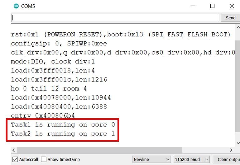
Open the serial monitor and you will be able to view the core where each task is being run. In our case, it is core0 for task1( blinking green LED) and core1 for task2 (blinking red LED).
Conclusion
In conclusion, we were able to learn about ESP32 dual core and were also able to create and run tasks on both the cores simultaneously. By default, the Arduino IDE runs the program code on ESP32’s core1 but now you can easily utilize ESP32’s core0 as well by following this tutorial.
Other FreeRTOS tutorials:
- Arduino FreeRTOS Queue Management – How to use Queues
- FreeRTOS Arduino: Changing the Priority of a Task
- How to use FreeRTOS structure Queue to Receive Data from Multiple Tasks
- FreeRTOS Arduino : How to Delete Tasks with vTaskDelete() API
- FreeRTOS Arduino: How to use Queue Set
- FreeRTOS Arduino: How to Create Mailbox with Queues
- FreeRTOS Software Timers with Arduino – Create One-shot and Auto-Reload Timer
- FreeRTOS Binary Semaphore – Examples of Tasks Interrupt Synchronization using Arduino
- FreeRTOS Counting Semaphore Examples with Arduino
- FreeRTOS Mutex Tutorial with Arduino – Avoid Priority Inversion
- Arduino FreeRTOS Recursive Mutex to avoid Deadlocks
- FreeRTOS Interrupt Management Examples with Arduino
Hi there can u plz help me in understanding the code for ac current measurement using pic controller.
I realy loved this article. I don’t know why I had not seen before, but I did learn from it. Thank you.