In this user guide, we will build an ESP32 web server which will act as a remote serial monitor. This will be achieved by using the WebSerial library and programming the ESP32 board in Arduino IDE. Additionally, we will use the ESPAsyncWebServer library as well. The web based serial monitor will work just the same way as the usual Arduino IDE serial monitor works for debugging purposes. By the end of this article, we will be able to send and receive text from the ESP32 to the web serial. We will show you how to build the web serial as well as how to use it with ESP32 module.
Recommended Components
The following components are used in this project or are helpful for building it with the ESP32.
| Component | How it’s used in this project | Buy on Amazon |
|---|---|---|
| ESP32 Development Board (DevKit V1) | Runs the WebSerial web server sketch and hosts the remote serial monitor. | Check Price |
| Micro USB Cable | Programs the ESP32 and powers it from your computer. | Check Price |
| Breadboard | Holds the ESP32 and any test wiring for the project. | Check Price |
| Jumper Wires | Make the connections between the ESP32 and your circuit. | Check Price |
As an Amazon Associate we earn from qualifying purchases. Prices and availability are accurate as of the date/time indicated and are subject to change.
Project Overview
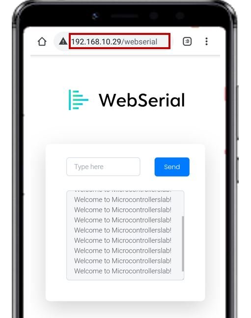
We aim to build a web server which will act as a serial monitor used for debugging purposes. After making a serial connection with the ESP32 board, it will be able to receive messages from the module as well as send them to our module. The figure below shows the web page which will act as the web based serial monitor.
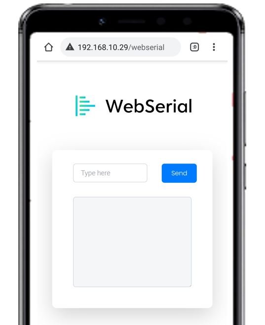
If you do not have access to the regular serial monitor, this web based serial monitor will be very convenient to use while working with ESP32 projects. One of the advantages is that you can open several web serials at a time. Additionally, it is compatible with WebSockets as well making it a great choice to use.
In the Web serial we use WebSerial.print() and WebSerial.print() to print messages on the monitor.
WebSerial.print(): prints the message on the web-based serial monitor on the same line
WebSerial.println(): prints the message on the web-based serial monitor on the next line
Setting up Arduino IDE
We will use Arduino IDE to program our ESP32 development board. Therefore, you should have the latest version of Arduino IDE. Additionally, you also need to install the ESP32 plugin in Arduino IDE. If your IDE does not have the plugin installed you can visit the link below:
Installing ESP32 library in Arduino IDE and upload code
Installing Libraries
We will require three libraries for this project. These include the ESPAsyncWebServer library, AsyncTCP library and the WebSerial library by Ayush Sharma
Installing ESPAsyncWebServer and AsyncTCP
The ESPAsyncWebServer library will help us in creating our web server easily. With this library, we will set an asynchronous HTTP server. AsyncTCP is another library that we will be incorporating as it a dependency for the ESPAsyncWebServer library. This library will not be used directly inside our program code and only acts as the base for the first library.
Both of these libraries are not available in the Arduino library manager so we will have to download and load them in the IDE ourselves. We will use GitHub to download the respective libraries and then place them in the library folder of our Arduino IDE.
Click ESPAsyncWebServer library and AsyncTCP library to open the respective GitHub pages for the libraries.
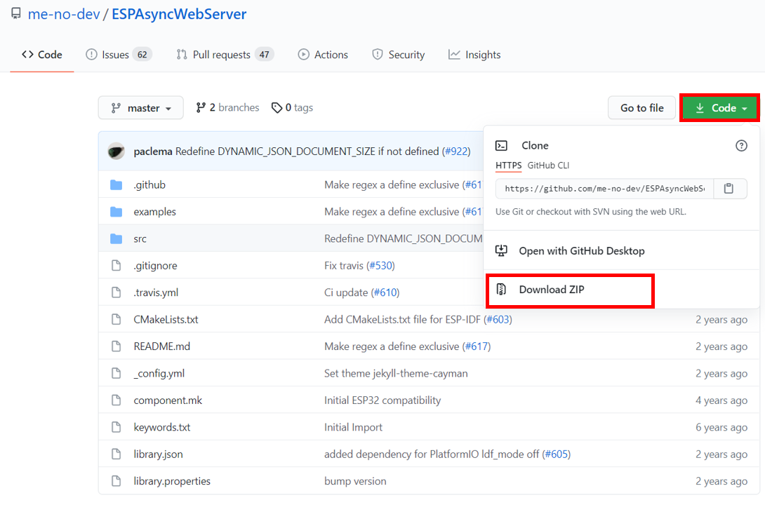
Click the Code button and go to the Download Zip option as highlighted in the figure. Your zip file will get downloaded to your computer right away. After the download is complete, extract the .zip file to the Arduino library folder. A similar process will apply to the installation of the AsyncTCP library as well. Make sure you rename the extracted files as ESPAsyncWebServer and AsyncTCP accordingly.
You can also go to Sketch > Include Library > Add .zip Library inside the IDE to add the libraries as well. Through this procedure now we will be able to use the functionalities of the libraries inside our Arduino IDE.
Installing WebSerial Library by Ayush Sharma
To build our web based serial monitor we will require the WebSerial library created by Ayush Sharma. This is available in the Arduino Library Manager. Open your Arduino IDE and go Tools > Manage Libraries. Type ‘WebSerial’ in the search bar and press enter. Install the latest version.

Arduino Sketch (ESP32 Web based Serial Monitor)
Open your Arduino IDE and go to File > New to open a new file. Copy the code given below in that file. We are using the example sketch provided with the WebSerial library with a few modifications. This sketch will display “Welcome to Microcontrollerslab!” on the web page after every 5 seconds. Additionally, we have also incorporated LED control as well. Whenever we will type ‘LED ON’ in the web serial, the onboard LED of the ESP32 will turn ON and vice versa.
/*
This sketch is based on the WebSerial library example: ESP32_Demo
  https://github.com/ayushsharma82/WebSerial
*/

#include <Arduino.h>
#include <WiFi.h>
#include <AsyncTCP.h>
#include <ESPAsyncWebServer.h>
#include <WebSerial.h>

#define LED_GPIO 2

AsyncWebServer server(80);

const char* ssid = "Your_SSID";
const char* password = "Your_Password";

void message(uint8_t *data, size_t len){
  WebSerial.println("Data Received!");
  String Data = "";
  for(int i=0; i < len; i++){
    Data += char(data[i]);
  }
  WebSerial.println(Data);
  if (Data == "LED ON"){
    digitalWrite(LED_GPIO, HIGH);
  }
  if (Data=="LED OFF"){
    digitalWrite(LED_GPIO, LOW);
  }
}

void setup() {
  Serial.begin(115200);
  pinMode(LED_GPIO, OUTPUT);

  WiFi.mode(WIFI_STA);
  WiFi.begin(ssid, password);
  if (WiFi.waitForConnectResult() != WL_CONNECTED) {
    Serial.printf("WiFi Failed!\n");
    return;
  }
  Serial.print("IP Address: ");
  Serial.println(WiFi.localIP());

  WebSerial.begin(&server);
  WebSerial.msgCallback(message);
  server.begin();
}

void loop() {
  WebSerial.println("Welcome to Microcontrollerslab!");
  delay(5000);
}
How does the Code Work?
Now, let us understand how each part of the code works.
Including Libraries
Firstly, we will import the necessary libraries. For this project, we are using five of them. Arduino.h, WiFi.h, ESPAsyncWebServer.h, AsyncTCP.h and WebSerial.h. As we have to connect our ESP32 to a wireless network hence we need WiFi.h library for that purpose. The other libraries are the ones that we recently downloaded and will be required for the building of the asynchronous web server which will act as a serial monitor.
#include <Arduino.h>
#include <WiFi.h>
#include <AsyncTCP.h>
#include <ESPAsyncWebServer.h>
#include <WebSerial.h>
Defining LED GPIO
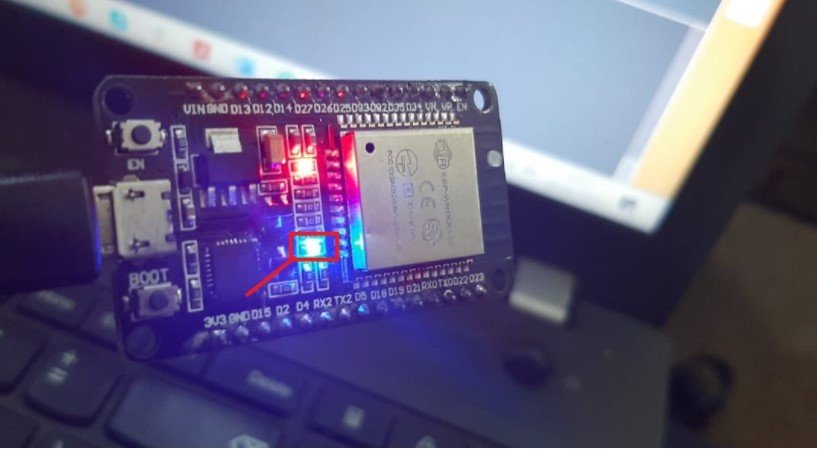
Next, we will define the GPIO which we will control via the web serial. For simplicity purposes, we will toggle the onboard LED of our ESP32 board. It is connected with GPIO2.
#define LED_GPIO 2Creating the AsyncWebServer Object
The AsyncWebServer object will be used to set up the ESP32 web server. We will pass the default HTTP port which is 80, as the input to the constructor. This will be the port where the server will listen to the requests.
AsyncWebServer server(80);Setting Network Credentials
Next, we will create two global variables, one for the SSID and the other for the password. These will hold our network credentials which will be used to connect to our wireless network. Replace both of them with your credentials to ensure a successful connection.
const char* ssid = "Your_SSID";
const char* password = "Your_Password";
void message()
Next, we will create a function called message() which takes in two parameters. This function will be called when the ESP32 board receives a message from the web serial. This message will get saved in the string variable named ‘Data’ and gets displayed in the web based serial monitor. Initially, we have defined it as an empty string. Notice that in order to print a text in the web based serial monitor we will use WebSerial.println(Data) instead of Serial.println(Data) where the latter prints the message in the regular serial monitor.
Additionally, we will be toggling the onboard LED in this function. When the user types ‘LED ON’ in the web serial, the onboard LED turns ON. This is done by using digitalWrite() and passing the LED GPIO and ‘HIGH’ as arguments inside the function. Likewise, when the user types ‘LED OFF’ in the web serial, the onboard LED turns OFF. this is done by using digitalWrite() and passing the LED GPIO and ‘LOW’ as arguments inside it.
void message(uint8_t *data, size_t len){
  WebSerial.println("Data Received!");
  String Data = "";
  for(int i=0; i < len; i++){
    Data += char(data[i]);
  }
  WebSerial.println(Data);
  if (Data == "LED ON"){
    digitalWrite(LED_GPIO, HIGH);
  }
  if (Data=="LED OFF"){
    digitalWrite(LED_GPIO, LOW);
  }
}
void setup()
Inside the setup() function, we will first set the LED’s GPIO pin as an output by using the pinMode() function. the LED GPIO (GPIO2) will be passed as a parameter inside the function which will be configured as an output pin.
pinMode(LED_GPIO, OUTPUT);The following section of code will connect our ESP32 board with the local network whose network credentials we already specified above. We will first set the ESP32 module in station mode and then use the WiFi.begin() function. The arguments will be the SSID and the password which we defined earlier in the code. After a successful connection is established, the IP address gets displayed on the web server. We will use this IP address to access our web server.
 WiFi.mode(WIFI_STA);
  WiFi.begin(ssid, password);
  if (WiFi.waitForConnectResult() != WL_CONNECTED) {
    Serial.printf("WiFi Failed!\n");
    return;
  }
  Serial.print("IP Address: ");
  Serial.println(WiFi.localIP());
Now we will use the WebSerial.begin() and pass the WebSerial object which we created previously inside it. This will initialize the web based serial monitor. The next step will be to register the message() function as a call-back function whenever the user sends a message from the web serial to the ESP32 board. This will be achieved by using WebSerial.msgCallback() and passing ‘message’ as the parameter.
WebSerial.begin(&server);
WebSerial.msgCallback(message);
To start the server, we will call begin() on our server object.
server.begin();void loop()
Inside the infinite loop() we will print “Welcome to Microcontrollerslab!” after every five seconds in the web serial monitor. This will be achieved by using WebSerial.println(). You can display any text according to your preference.
void loop() {
  WebSerial.println("Welcome to Microcontrollerslab!");
  delay(5000);
}
Demonstration
Make sure you choose the correct board and COM port before uploading your code to the board. Go to Tools > Board. Select ESP32 Dev Module.

Next, go to Tools > Port. Select the appropriate port through which your board is connected.

Click on the upload button to upload the code into the ESP32 development board.
After you have uploaded your code to the ESP32 development board press its ENABLE button.

In your Arduino IDE, open up the serial monitor. You will be able to see the IP address of your ESP32 module.
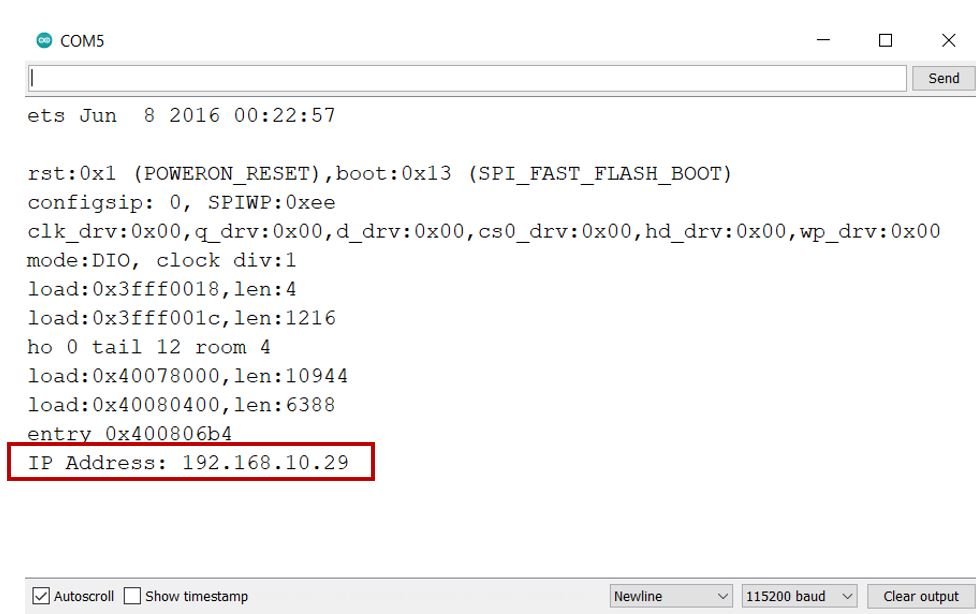
Copy that address into a web browser with /webserial and press enter.
The web based serial monitor will be displayed. Notice that after every 5 seconds, we are receiving a message (Welcome to Microcontrollerslab!) from the ESP32 module.
Now, we can also send messages from this web serial monitor to our ESP32 board. Type ‘LED ON’ in the Type here bar and click Send.
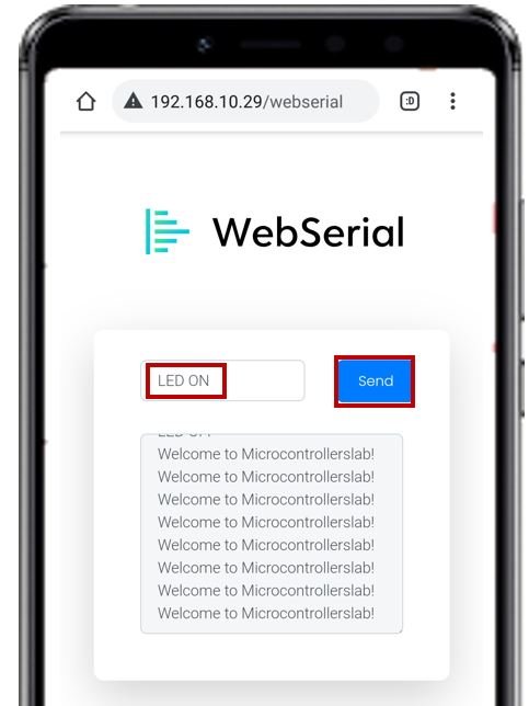
Just as you click the Send button the onboard LED will turn ON.
In the web based serial monitor you will be able to view the message ‘Data Received!’ and ‘LED ON.’

To turn the onboard LED OFF, type “LED OFF” in the web serial monitor and click Send. The LED will turn OFF. Likewise, In the web based serial monitor you will be able to view the message ‘Data Received!’ and ‘LED OFF.’

Conclusion
In conclusion, we were able to show you how to build and use a web based serial monitor easily using the WebSerial library created by Ayush Sharma. This web server is very advantageous if you are unable to serially connect your ESP32 module with a system. Additionally, it uses WebSocket and displays data in real-time which makes it quite handy.
For more ESP32 related tutorials visit the links below:
- ESP32 WebSocket Server using Arduino IDE – Control GPIOs and Relays
- ESP32/ESP8266 Web Server with Input Data on HTML Form using Arduino IDE
- ESP32 Server-Sent Events (SSE) Web Server (Arduino IDE)
- ESP32 Asynchronous Web Server using Arduino IDE and ESPAsyncWebServer library
- IBM Watson Cloud Platform with ESP32: Display sensor Readings