In this tutorial, we will learn how to use an external interrupt to wake up the ESP32 from a deep sleep. There are two external wake up resources available such as an ext0 and ext1. When the state of a GPIO pin is changed, the ESP32 will wake up from deep sleep. There are two types of external interrupt wake-ups in the ESP32. We will see examples to use both ext0 and ext1 as a wake up source.

Note: Only Real-time clock or RTC input-output pins can be used as a wake up source. Therefore, to make use of this external wake up we need to make sure that during deep sleep, the RTC peripherals are powered ON. Thus, we can only use the RTC GPIOs to induce the ext0, ext1 external wake-up.
The figure below shows the RTC GPIO pinout which we can use, highlighted in red:

For ESP32 Devkit V1- DOIT we can use the following 14 GPIO pins:
- RTC_GPIO0 : GPIO36
- RTC_GPIO3: GPIO39
- RTC_GPIO9: GPIO32
- RTC_GPIO8: GPIO33
- RTC_GPIO6: GPIO25
- RTC_GPIO7: GPIO26
- RTC_GPIO17: GPIO27
- RTC_GPIO16: GPIO14
- RTC_GPIO15: GPIO12
- RTC_GPIO14: GPIO13
- RTC_GPIO11: GPIO0
- RTC_GPIO13: GPIO15
- RTC_GPIO12: GPIO2
- RTC_GPIO10: GPIO4
- RTC_GPIO4: GPIO34
- RTC_GPIO5: GPIO35
Recommended Components
The following components are used in this project or are helpful for building it with the ESP32.
| Component | How it’s used in this project | Buy on Amazon |
|---|---|---|
| ESP32 Development Board (DevKit V1) | The main board that runs the project firmware. | Check Price |
| Micro USB Cable | Connects the board to your computer to upload code and power it. | Check Price |
| Breadboard | Holds the board and components together while you wire up the project. | Check Price |
| Jumper Wires | Make the connections between the board and any external parts. | Check Price |
| Tactile push button | Drives the external wake-up GPIO to bring the ESP32 out of deep sleep. | Check Price |
As an Amazon Associate we earn from qualifying purchases. Prices and availability are accurate as of the date/time indicated and are subject to change.
How to use External Interrupts as a wake up Source for ESP32
Ext0 and Ext1 are two external interrupts available with ESP32 microcontroller. These external interrupts can be used to wake up the ESP32 from deep sleep mode.
To use Ext0 or Ext1 as a wake-up source, you need to configure the corresponding GPIO pin as an input and enable the external interrupt using the ESP32 SDK’s GPIO API. Once the external interrupt is enabled, the ESP32 will be able to wake up from deep sleep mode when the corresponding pin changes state.
Ext0 and Ext1 are useful for waking up the ESP32 from deep sleep mode in response to external events, such as button presses or sensor readings.
External Wake Up – ext0
In this section, we will see how to configure and use external wake up ext0 as a source to exit deep sleep mode. Ext0 is associated with RTC GPIO pins, and it can be used to wake up the ESP32 from deep sleep using a rising or falling edge on the pin. The RTC module triggers a wake up interrupt when one of the RTC GPIO pins is set to a predefined logic level.
We will use the following function to wake our ESP32 board from deep sleep via ext0 wake up in Arduino IDE:
esp_sleep_enable_ext0_wakeup(GPIO_NUM_X, level)The esp_sleep_enable_ext0_wakeup(GPIO_NUM_X, level) function defines how ext0 wakes up ESP32 from deep sleep. The first parameter is the RTC GPIO pin that will trigger the wakeup and the second parameter is the state (1 or 0) of that pin.
This function takes in the following parameters:
The first argument is the RTC GPIO pin. This is the object which denotes the GPIO which would be set up as the wake-up source. Additionally, the last argument is the trigger level. This trigger level defines the state of the GPIO pin as a source of wake up. It can be one of the following types:
- 1: Wake up process is triggered when the GPIO is in a high state.
- 0: Wake up process is triggered when the GPIO is in a low state.
External Wake Up – ext1
Ext1, on the other hand, can be used to wake up the ESP32 from deep sleep using multiple RTC GPIO pins. This is used when we want to have more than one RTC GPIO pin as a source to trigger the external wake-up. Only the RTC controller is powered on during deep sleep. Therefore, we can only use the RTC GPIOs which we previously stated. We will use the following function to wake our ESP32 board from deep sleep via ext1 wake up in Arduino IDE:
esp_sleep_enable_ext1_wakeup(bitmask, mode)The esp_sleep_enable_ext1_wakeup(bitmask, mode) function defines how ext1 wakes up ESP32 from deep sleep.
This function takes on the following parameters:
The first argument is the bitmask of the GPIO pin number which will trigger the wakeup. The second argument is the mode used to wake up the development board. This shows the state of the GPIO pin. It can be one of the following:
- ESP_EXT1_WAKEUP_ANY_HIGH: Wake up process is triggered when ANY GPIO is in a high state.
- ESP_EXT1_WAKEUP_ALL_LOW: Wake up process is triggered when ALL the GPIOs are in a low state.
ESP32 EXT0 External Wake-Up from Deep Sleep Example
Let’s take a look at a simple example demonstrating the ext0 external wake-up feature of the ESP32. We will demonstrate how to use a push button as a wake-up source from deep sleep mode. The ESP32 will remain in deep sleep mode until the user presses the push button, which will trigger the ext0 external interrupt and wake up the ESP32 from deep sleep mode into active mode.
To use ext0 as a wake-up source from deep sleep mode, we need to connect the push button to the GPIO pin assigned as ext0 (by default, GPIO 26). We also need to configure the GPIO pin as an input, enable the ext0 external interrupt, and enter deep sleep mode. When the push button is pressed, it will cause a change in the state of the GPIO pin, triggering the ext0 external interrupt and waking up the ESP32 from deep sleep mode.
Once the ESP32 is woken up from deep sleep mode, it will resume executing the code after printing the reason of wake-up. The code can then handle the event that triggered the wake-up, such as reading sensor data or sending a message over a network.
We will need the following components.
Required Components
- ESP 32 Devkit board
- One Push button
- One 10k ohm resistor
- Breadboard
- Connecting Wires
Schematic Diagram
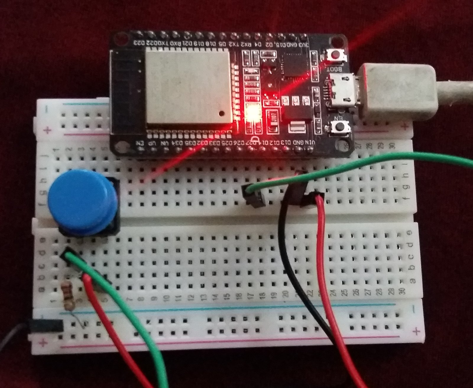
As shown in the schematic diagram below, we will connect a push button to one of the RTC GPIO pins, specifically GPIO14 in this example. To ensure proper functioning of the push button, we also connected a 10k ohm pull-down resistor between GPIO14 and ground. One terminal of the push button is connected to the 3.3V power supply, and the other terminal is connected to GPIO14, which will sense a change in the logic level when the button is pressed.
By connecting the push button to GPIO14, we can use it as an external wake-up source for the ESP32 microcontroller when it is in deep sleep mode. When the push button is pressed, it will change the logic level on GPIO14, triggering the external interrupt and waking up the ESP32 from deep sleep mode.

ESP32 ext0 External Wake Up Code
Open your Arduino IDE and go to File > Examples > ESP32 > Deep Sleep > ExternalWakeUp. The following sketch will open up. This example sketch has set GPIO33 as the triggering pin although in our case the push button is connected with GPIO14. Thus, we will change the GPIO pin which will cause the trigger for the wake up inside the sketch. You can use any suitable input GPIO pin but remember to replace it appropriately in the program code.
/*
Deep Sleep with External Wake Up
=====================================
This code displays how to use deep sleep with
an external trigger as a wake up source and how
to store data in RTC memory to use it over reboots

This code is under Public Domain License.

Hardware Connections
======================
Push Button to GPIO 14 pulled down with a 10K Ohm
resistor

NOTE:
======
Only RTC IO can be used as a source for external wake
source. They are pins: 0,2,4,12-15,25-27,32-39.

Author:
Pranav Cherukupalli <cherukupallip@gmail.com>
*/

#define BUTTON_PIN_BITMASK 0x200000000 // 2^33 in hex

RTC_DATA_ATTR int bootCount = 0;

/*
Method to print the reason by which ESP32
has been awaken from sleep
*/
void print_wakeup_reason(){
  esp_sleep_wakeup_cause_t wakeup_reason;

  wakeup_reason = esp_sleep_get_wakeup_cause();

  switch(wakeup_reason)
  {
    case ESP_SLEEP_WAKEUP_EXT0 : Serial.println("Wakeup caused by external signal using RTC_IO"); break;
    case ESP_SLEEP_WAKEUP_EXT1 : Serial.println("Wakeup caused by external signal using RTC_CNTL"); break;
    case ESP_SLEEP_WAKEUP_TIMER : Serial.println("Wakeup caused by timer"); break;
    case ESP_SLEEP_WAKEUP_TOUCHPAD : Serial.println("Wakeup caused by touchpad"); break;
    case ESP_SLEEP_WAKEUP_ULP : Serial.println("Wakeup caused by ULP program"); break;
    default : Serial.printf("Wakeup was not caused by deep sleep: %d\n",wakeup_reason); break;
  }
}

void setup(){
  Serial.begin(115200);
  delay(1000); //Take some time to open up the Serial Monitor

  //Increment boot number and print it every reboot
  ++bootCount;
  Serial.println("Boot number: " + String(bootCount));

  //Print the wakeup reason for ESP32
  print_wakeup_reason();

  /*
  First we configure the wake up source
  We set our ESP32 to wake up for an external trigger.
  There are two types for ESP32, ext0 and ext1 .
  ext0 uses RTC_IO to wakeup thus requires RTC peripherals
  to be on while ext1 uses RTC Controller so doesnt need
  peripherals to be powered on.
  Note that using internal pullups/pulldowns also requires
  RTC peripherals to be turned on.
  */
  esp_sleep_enable_ext0_wakeup(GPIO_NUM_14,1); //1 = High, 0 = Low

  //If you were to use ext1, you would use it like
  //esp_sleep_enable_ext1_wakeup(BUTTON_PIN_BITMASK,ESP_EXT1_WAKEUP_ANY_HIGH);

  //Go to sleep now
  Serial.println("Going to sleep now");
  esp_deep_sleep_start();
  Serial.println("This will never be printed");
}

void loop(){
  //This is not going to be called
}
How does the Code Work?
This example sketch shows both types of external wake up i.e. ext0 and ext1. In this section, we will explain the parts related to ext0. The parts for ext1 have been commented on inside the code.
Saving Boot Count in RTC Memory
ESP32 has an 8kb SRAM for the RTC controller which is also known as RTC fast memory and this memory can be used to save data. The data stored on this memory will remain saved during deep sleep but it will be erased during boot-up. Hence, we can use this memory to save data before putting ESP32 into deep sleep mode.
Now we will save the number of times our ESP32 board woke up from deep sleep inside the variable ‘bootCount.’
This will be saved in the RTC Memory of the development board by using ‘RTC_DATA_ATTR’ before defining the bootCount variable.
RTC_DATA_ATTR int bootCount = 0;ESP32 Wake Up Reason
This print_wakeup_reason() function prints the reason for the ESP32 waking up from deep sleep. The method gets the wakeup reason using the function esp_sleep_get_wakeup_cause() and prints the corresponding message using a switch-case statement. The possible wakeup reasons include external signals using RTC_IO or RTC_CNTL pins, a timer, touchpad, or ULP program. If the wakeup reason is not caused by deep sleep, a message with the wakeup reason code is printed.
/*
Method to print the reason by which ESP32
has been awaken from sleep
*/
void print_wakeup_reason(){
  esp_sleep_wakeup_cause_t wakeup_reason;

  wakeup_reason = esp_sleep_get_wakeup_cause();

  switch(wakeup_reason)
  {
    case ESP_SLEEP_WAKEUP_EXT0 : Serial.println("Wakeup caused by external signal using RTC_IO"); break;
    case ESP_SLEEP_WAKEUP_EXT1 : Serial.println("Wakeup caused by external signal using RTC_CNTL"); break;
    case ESP_SLEEP_WAKEUP_TIMER : Serial.println("Wakeup caused by timer"); break;
    case ESP_SLEEP_WAKEUP_TOUCHPAD : Serial.println("Wakeup caused by touchpad"); break;
    case ESP_SLEEP_WAKEUP_ULP : Serial.println("Wakeup caused by ULP program"); break;
    default : Serial.printf("Wakeup was not caused by deep sleep: %d\n",wakeup_reason); break;
  }
}
Inside the setup() function, we will open a serial connection at a baud rate of 115200 and add a delay of 1 second to open the serial monitor.
Serial.begin(115200);
delay(1000);
Then we will increment the bootCount variable to 1 every time the ESP32 board wakes up from deep sleep. On the serial monitor, the number of times the ESP32 module booted will be displayed automatically.
++bootCount;
Serial.println("Boot number: " + String(bootCount));
Now, we will call the print_wakeup_reason() function which was defined earlier to display the reason for the wake up. The message will be displayed on the serial monitor.
print_wakeup_reason();To wake the ESP32 board from deep sleep via ext0, we will use the following function in our code:
The first argument specifies the GPIO pin number that is connected to the push button. In our case, we have connected the push button to GPIO14, but any appropriate RTC GPIO pin can be used for this purpose.
The second parameter, which is set to 1 in this example, specifies that the wake-up will be triggered when the push button is in a high state, or logic level 1.
esp_sleep_enable_ext0_wakeup(GPIO_NUM_14, 1);By calling this function before putting the ESP32 into deep sleep mode, we are configuring it to wake up when the push button connected to the specified GPIO pin is pressed.
Finally, these lines put the ESP32 into deep sleep mode using esp_deep_sleep_start() after printing a message to the serial monitor. The ESP32 will consume minimal power until woken up by an external interrupt. Any code following the esp_deep_sleep_start() function call will not be executed until the ESP32 is woken up.
Serial.println("Going to sleep now");
esp_deep_sleep_start();
Serial.println("This will never be printed");
Demonstration
To see the demonstration of the above code, upload the code to Arduino. Before uploading the code, make sure to select the ESP32 board from Tools > Board and also select the correct COM port to which the ESP32 board is connected from Tools > Port.
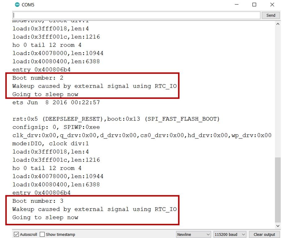
Once the code is uploaded to ESP32, open the serial monitor of Arduino IDE and set the baud rate to 115200. Press the push button and notice the ESP32 board waking up from deep sleep. you can view the messages on the serial monitor showing the boot count, wake up reason, and going back to sleep message.
In summary, the ext0 external wake-up feature of the ESP32 allows the ESP32 to enter deep sleep mode and wake up in response to an external event, such as a push button press, conserving power and extending the battery life of battery-powered devices.
ESP32 ext1 External Wake Up from Deep Sleep Example
In the following example, we will demonstrate how to use the ext1 external wake-up feature of the ESP32 microcontroller with the help of two push buttons. We will use the same sketch that we used for ext0. The push buttons will act as wake-up sources for the ESP32 board.
To build this circuit, we will need the following components.
- ESP 32 Devkit board
- Two Pushbuttons
- Two 10k ohm resistors
- Breadboard
- Connecting Wires
Schematic Diagram
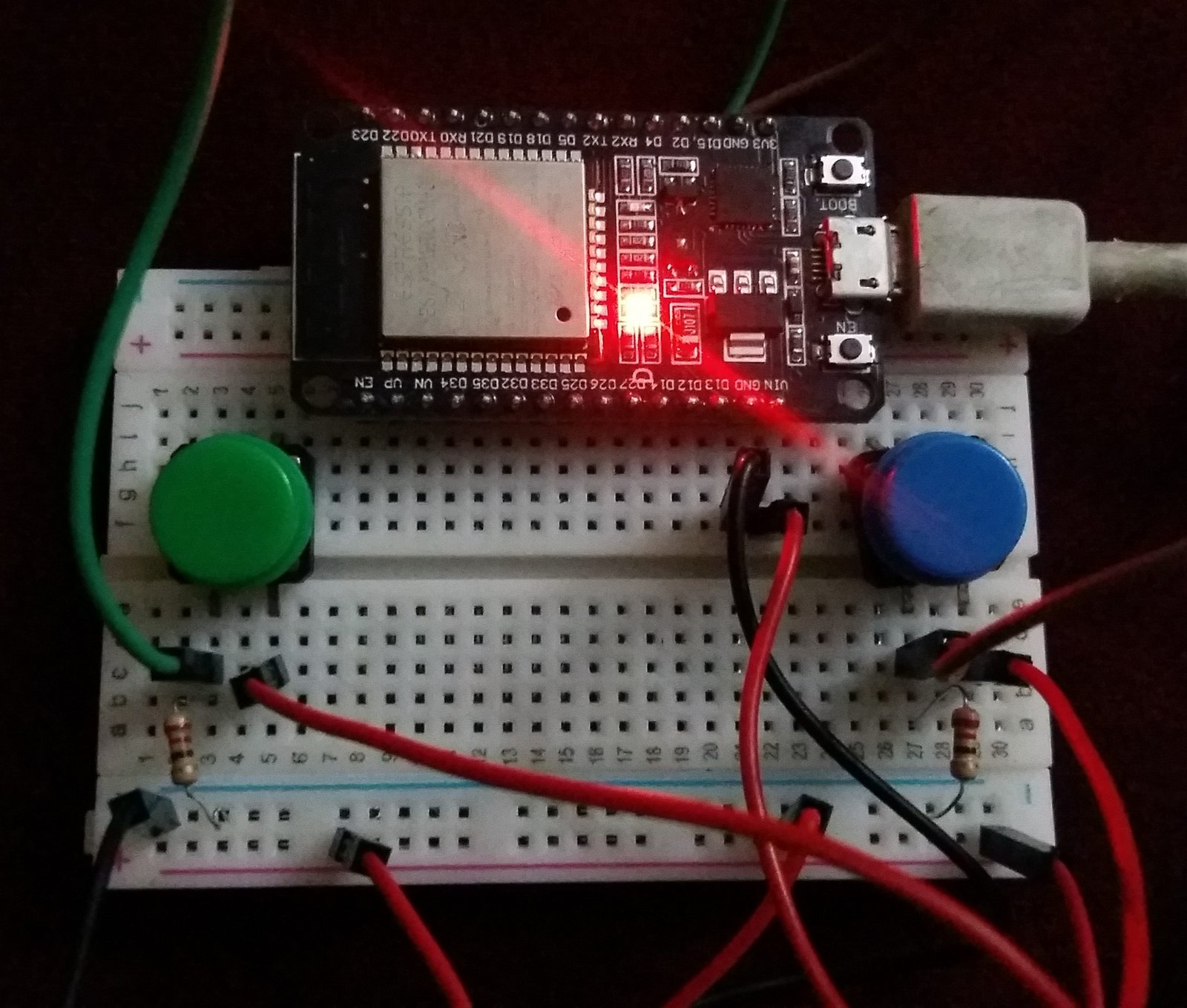
As shown in the schematic, both terminals of the two push buttons are connected to ground through two separate 10k ohm resistors, and the other terminals are connected to GPIO2 and GPIO15, respectively. Both buttons are also connected to the 3.3V power source pins.
By connecting the push buttons to GPIO2 and GPIO15, we can use them as external wake-up sources for the ESP32 microcontroller when it is in deep sleep mode. When either push button is pressed, it will change the logic level on the corresponding GPIO pin, triggering the external interrupt and waking up the ESP32 from deep sleep mode.
Hence, by connecting multiple push buttons to different GPIO pins, we can create multiple external wake-up sources for the ESP32, allowing for more versatile and complex wake-up scenarios. and demonstrating ext1 feature to use multiple RTC GPIOs as a wake up sources.

ESP32 ext1 External Wake Up Code
For this example, we will use the same sketch as we did for ext0. However, we will need to make some changes to the code to enable the use of ext1. Specifically, we will need to uncomment the lines of code for ext1 in the sketch and comment out the parts where ext0 is being used. Additionally, we will need to convert the GPIO15 and GPIO2 pin numbers into bit mask numbers. This has already been done in the program code provided below:
/*
Deep Sleep with External Wake Up
=====================================
This code displays how to use deep sleep with
an external trigger as a wake up source and how
to store data in RTC memory to use it over reboots

This code is under Public Domain License.

Hardware Connections
======================
Push Button to GPIO 33 pulled down with a 10K Ohm
resistor

NOTE:
======
Only RTC IO can be used as a source for external wake
source. They are pins: 0,2,4,12-15,25-27,32-39.

Author:
Pranav Cherukupalli <cherukupallip@gmail.com>
*/

#define BUTTON_PIN_BITMASK 0x8004 // GPIOs 2 and 15

RTC_DATA_ATTR int bootCount = 0;

/*
Method to print the reason by which ESP32
has been awaken from sleep
*/
void print_wakeup_reason(){
  esp_sleep_wakeup_cause_t wakeup_reason;

  wakeup_reason = esp_sleep_get_wakeup_cause();

  switch(wakeup_reason)
  {
    case ESP_SLEEP_WAKEUP_EXT0 : Serial.println("Wakeup caused by external signal using RTC_IO"); break;
    case ESP_SLEEP_WAKEUP_EXT1 : Serial.println("Wakeup caused by external signal using RTC_CNTL"); break;
    case ESP_SLEEP_WAKEUP_TIMER : Serial.println("Wakeup caused by timer"); break;
    case ESP_SLEEP_WAKEUP_TOUCHPAD : Serial.println("Wakeup caused by touchpad"); break;
    case ESP_SLEEP_WAKEUP_ULP : Serial.println("Wakeup caused by ULP program"); break;
    default : Serial.printf("Wakeup was not caused by deep sleep: %d\n",wakeup_reason); break;
  }
}

/*
Method to print the GPIO that triggered the wakeup
*/
void print_GPIO_wake_up(){
  uint64_t GPIO_reason = esp_sleep_get_ext1_wakeup_status();
  Serial.print("GPIO that triggered the wake up: GPIO ");
  Serial.println((log(GPIO_reason))/log(2), 0);
}

void setup(){
  Serial.begin(115200);
  delay(1000); //Take some time to open up the Serial Monitor

  //Increment boot number and print it every reboot
  ++bootCount;
  Serial.println("Boot number: " + String(bootCount));

  //Print the wakeup reason for ESP32
  print_wakeup_reason();

  //Print the GPIO used to wake up
  print_GPIO_wake_up();

  /*
  First we configure the wake up source
  We set our ESP32 to wake up for an external trigger.
  There are two types for ESP32, ext0 and ext1 .
  ext0 uses RTC_IO to wakeup thus requires RTC peripherals
  to be on while ext1 uses RTC Controller so doesnt need
  peripherals to be powered on.
  Note that using internal pullups/pulldowns also requires
  RTC peripherals to be turned on.
  */
  //esp_deep_sleep_enable_ext0_wakeup(GPIO_NUM_15,1); //1 = High, 0 = Low

  //If you were to use ext1, you would use it like
  esp_sleep_enable_ext1_wakeup(BUTTON_PIN_BITMASK,ESP_EXT1_WAKEUP_ANY_HIGH);

  //Go to sleep now
  Serial.println("Going to sleep now");
  delay(1000);
  esp_deep_sleep_start();
  Serial.println("This will never be printed");
}

void loop(){
  //This is not going to be called
}
How does the Code Work?
We will explain the parts which are different in ext1 as compared to the previous sketches.
Defining BUTTON_PIN_BITMASK
Firstly, we will use bit mask values for the GPIO pins which we are using as wake up sources. As you already know, for ext1 we will use the esp_sleep_enable_ext1_wakeup() function. This takes in two parameters. For the first parameter we will have to specify the bit mask value for GPIO15 and GPIO2.
Bitmask for single GPIO
To find the GPIO bitmask we will follow the steps given below.
- First, calculate 2^GPIO_Pin_Number. Save this number.
- Now, go to an online decimal-to-hexadecimal number converter like this. Convert the number which you obtained above in hexadecimal.
- If using a single GPIO pin then this is the value that you will use when defining the BUTTON_PIN_BITMASK variable. However, we are using two push buttons each attached to a different GPIO pin i.e. GPIO15 and GPIO2. We will have to perform additional steps for this purpose.
Bitmask for multiple GPIOs
- For GPIO15 and GPIO2 follow the steps below:
Calculate 2^15 + 2^2 - Now convert the value obtained into hexadecimal. It will be 8004.
- This is the value which we will define as ‘BUTTON_PIN_BITMASK.’
#define BUTTON_PIN_BITMASK 0x8004If you increase the number of GPIOs just include it in the first step e.g. 2^GPIO_X + 2^GPIO_Y + 2^GPIO_Z + …
print_GPIO_wake_up()
We will use the print_GPIO_wake_up() function to determine which GPIO pin caused the ESP32 board to wake up from deep sleep. Inside this function we will call the esp_sleep_get_ext1_wakeup_status() function and save the value it returns in the variable ‘GPIO_reason.’ This value will be equal to 2^GPIO_PIN_NUMBER. To display the GPIO pin number in decimal we will use an appropriate conversion and print it in the serial monitor.
void print_GPIO_wake_up(){
  int GPIO_reason = esp_sleep_get_ext1_wakeup_status();
  Serial.print("GPIO that triggered the wake up: GPIO ");
  Serial.println((log(GPIO_reason))/log(2), 0);
}
Enabling ext1
We will use the following function to enable ext1 as the wake up source for our ESP32 module. This will cause GPIO15 and GPIO2 to act as triggering sources whenever their state is high.
esp_sleep_enable_ext1_wakeup(BUTTON_PIN_BITMASK,ESP_EXT1_WAKEUP_ANY_HIGH);Demonstration
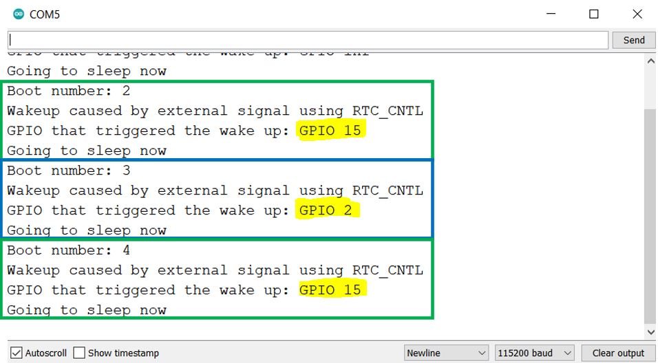
Once the code is uploaded to ESP32, open the serial monitor of Arduino IDE and set the baud rate to 115200. Press the pushbuttons and notice the ESP32 board waking up from deep sleep. You can view the messages on the serial monitor showing the boot count, wake up reason, the GPIO which triggered the wake up, and then going back to sleep message.
You may also like to read:
“Once the ESP32 is woken up from deep sleep mode, it will resume executing the code from where it left off before entering deep sleep mode.”
This statement is incorrect and contradicted within this article.
Also “Only RTC IO can be used as a source for external wake
source. They are pins: 0,2,4,12-15,25-27,32-39.”
This is also contradicted within the article wrt GPIO35 and GPIO34 which are not listed for RTC_GPIO within the article.
Sorry if this is nit-picking – am struggling with an “ESP32 S2 Mini” that doesn’t wake from deep sleep when I think it should. None-the-less a heart felt thank you for the article.
Thank you for pointing out mistakes we have just fixed them. Thanks