In this user guide, you will learn how to use the IBM Watson cloud platform with the ESP32 module. Through this secure IoT platform, we’ll show you how to send sensor readings to the IBM Watson cloud platform. Firstly, we will see how to set up your ESP32 development board with IBM cloud services. Secondly, we will see the step-by-step process to create an account.
We will use Arduino IDE to program our ESP32 board which will be connected to a DHT22 sensor. The sensor data from DHT22 will be displayed on the IBM Watson Cloud dashboard. Most importantly, you can access the dashboard from anywhere in the world. Any appropriate sensor can be used such as DS18B20, BME680, LM35, and MPU6050 but for this project, we will use a DHT22 sensor which is used to measure temperature and humidity. Through Amazon web services you will be able to control sensor readings using your mobile as well as on the web dashboard.
We also built our personal ESP32 IoT application by using Google Firebase and MIT App Inventor. This displayed DHT11/DHT22 sensor readings on the Android application:
ESP32 Send Sensor Readings to Google Firebase and Build an Android app to display Data
Additionally, you can also take a look at our Amazon Web Services (AWS) MQTT tutorial with ESP32 where we published DHT22 sensor data to its IoT core:
AWS IoT MQTT with ESP32: Publish Sensor Readings
This article is divided into these sub-topics:
- Introduction of DHT22 sensor and its connection with an ESP32 board.
- Introduction of IBM Watson and setting up ESP32 with IBM Watson cloud platform
- Setting up Arduino IDE and programming the module
- Demonstration
Recommended Components
The following components are used in this project or are helpful for building it with the ESP32.
| Component | How it’s used in this project | Buy on Amazon |
|---|---|---|
| ESP32 Development Board (DevKit V1) | Runs the project code and connects over Wi-Fi to publish the sensor readings to the IBM Watson IoT cloud. | Check Price |
| Micro USB Cable | Flashes the Arduino sketch from your computer and powers the ESP32 while it streams data to the dashboard. | Check Price |
| Breadboard | Holds the ESP32 and the DHT22 sensor so you can wire the circuit without soldering. | Check Price |
| Jumper Wires | Connect the DHT22 sensor’s data, VCC, and GND pins to the ESP32 GPIOs. | Check Price |
As an Amazon Associate we earn from qualifying purchases. Prices and availability are accurate as of the date/time indicated and are subject to change.
Introduction to DHT22 sensor
The DHT22 is an inexpensive sensor which measures relative humidity and temperature sensor. It provides a calibrated digital output with a 1-wire protocol. It measures temperature and humidity with higher accuracy and supports a wider range as compared to DHT11.
DHT sensors are pre-calibrated. We can directly connect them with ESP32 board to obtain sensor output reading. They are internally composed of a humidity sensing sensor and a thermistor. These two components measure humidity and temperature.
DHT22 Pinout
The following figure shows the pinout diagram of DHT sensors. DHT sensor consists of four pins. But on DHT modules only three pins are exposed to the pinout of the module and the 10k ohm pull-up resistor is internally connected to pin 2.
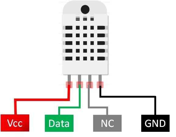
The following lists the pinout of the DHT sensor and their brief description. Pin number starts from left to right when you hold the sensor from the front end. It also shows how these pins will be connected with the ESP32 board.
| DHT22 Pin | ESP32 |
| 1 (VCC) | 3.3V |
| 2 (Data Out) | Any GPIO pins of ESP32 board along with 10k ohm pull-up resistor |
| 3 (NC) | Not used |
| 4 (GND) | Ground |
- VCC is the power supply pin. Apply voltage in a range of 3.3 V to 5.0 V to this pin
- Data Out is the digital output pin. It sends out the value of measured temperature and humidity in the form of serial data
- N/C is not connected
- GND: Connect the GND pin
DHT22 Interfacing with ESP32 board
Connect the DHT22 to ESP32 along with a 10K ohm pull-up resistor. The connection diagram is shown in the picture below.
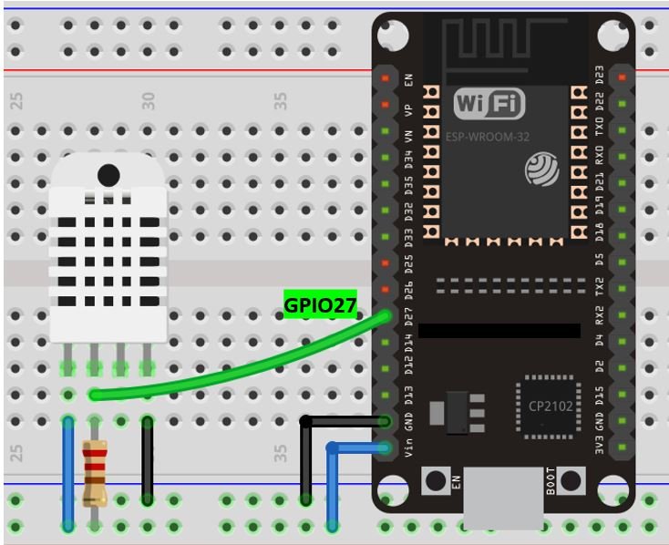
- The first pin is the power supply (VCC) pin. Connect it with the 3.3 volt pin of ESP32.
- Data out is the pin through which we get temperature and humidity samples from the DHT sensor. Connect this pin with GPIO27 of ESP32 and also connect the data pin with a 10k pull-up resistor. You can also use any appropriate digital pin of ESP32.
A Pull-up resistor is used to keep the data pin high for proper communication between the microcontroller and sensor. You can check the datasheet of DHT11 and DHT22 to get more information about it. DHT22 is also known by the name of AM2302.
- Third pin is not used
- Connect the fourth pin (GND) to the ground pin of the ESP32 board
IBM Watson Cloud Platform
IBM Watson cloud platform provides secure IoT services with visual dashboards, cognitive APIs, data storage, device registration, connectivity and control etc. With IBM Watson cloud platform, the user is granted inexpensive cloud computing services which are reliable and interactive. For the user, it becomes extremely fun and easy to use this application to build IoT projects from anywhere over the internet. Only the IBM Watson account and a steady internet connection in your device (smartphone, laptop, tablet, etc.) are a requirement.
Although this platform is a bit complicated as compared to the other web services which we have covered but it will be very easy to set up your ESP32 module once you go through this article. Make sure to follow the steps in order.
Setting up IBM Cloud Account
Before proceeding with the project let us understand the steps which have to be followed to successfully connect with the IBM Cloud IoT application.
Firstly, type https://www.ibm.com/cloud in your browser search tab and press enter.
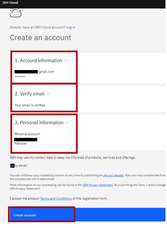
This will open the IBM cloud main page. Click ‘Create IBM Cloud Account.’

This will open a new window where we will enter our details to sign up for the account. Enter an email address and password. You will then be required to verify this email address. After the email is successfully verified you will be asked to put in some personal details including your full name and country. Then click ‘Create Account.’
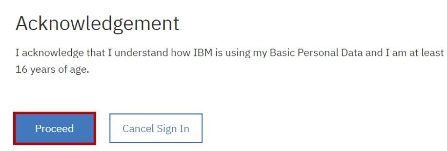
You will be redirected to a new page where they will ask for your acknowledgement. Click ‘Proceed.’
Now the IBM cloud dashboard will load. You use IBM services we will have to first create a resource.

This will open the IBM cloud catalog. Scroll down the categories and select ‘Internet of Things.’

Now choose Internet of Things protocol.

This will open the Internet of Things Platform. Leave the settings as default and in the right hand corner you will be able to view Summary. Click ‘Create’ to proceed further.

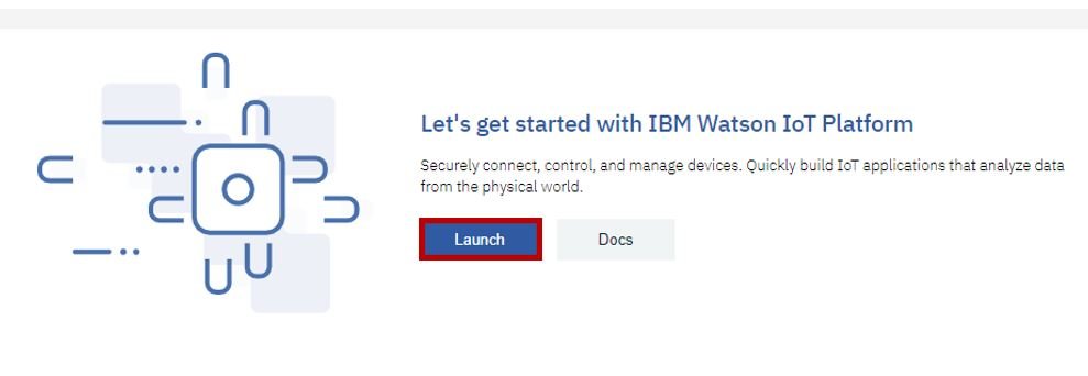
It will take a few moments to create the resource. A new window will open leading you to the Service Details. Click ‘Launch’ to launch the newly created resource.
Adding Device
Now a new tab will open and the IBM Watson IoT Platform Dashboard will open. At the top you will see ‘Add device.’ Click it.

To connect our ESP32 board with the cloud platform we will add its details. The first step is to add the device type and device id. We will specify the device type as ‘ESP32’ and for device id mention the unique chip ID of our ESP32 board. You will specify your own details. Click ‘Next’ to move ahead.

Now specify the device information. We will leave it as default and move to Next.

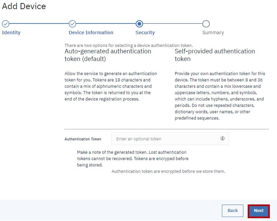
Leave the security settings as default as well. Click ‘Next.’
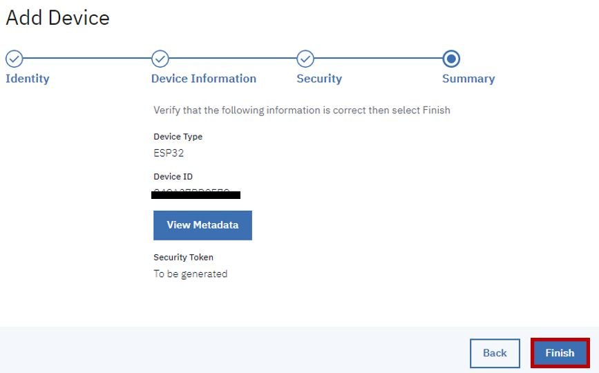
Now you will be able to view the summary of your device. Click ‘Finish.’
Now you will be able to view the device authorization token. Save it and do not share it with anyone for security reasons. We will use it later while programming our ESP32 board.

Building Dashboard
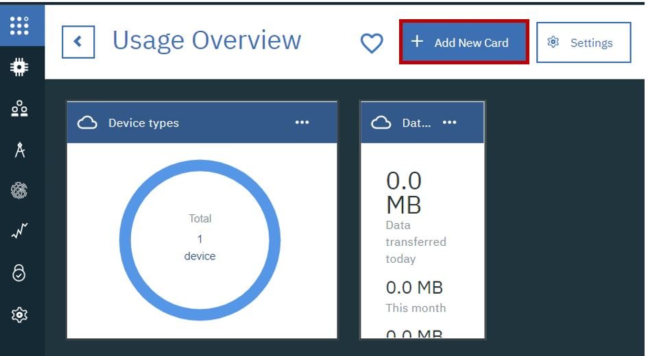
Now we will build our dashboard to view the sensor data in different charts/graphs. Go to Boards then Usage Overview as shown below:

The following page will open. Click ‘Add New Card.’
We want to display our sensor readings in a line chart. So we will choose that. You can view various other visualisations as well. Choose the one which suits you.

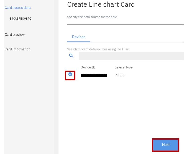
Now you will be asked to connect a device. We will connect the ESP32 device which we previously added. Click ‘Next’ to proceed further.
Now you will be asked to mention the details of the data set which is to be connected which will be displayed on the line chart. This chart will display the temperature sensor readings which we will obtain from our DHT22 sensor. So we will set the name of our event as ‘Data1.’ Our temperature reading will be sent to this event. Set the property, name, type and unit as shown in the picture. Click ‘Next’ to proceed further.

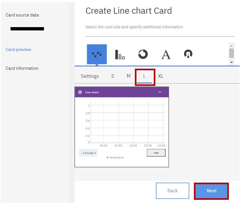
Now specify the size of the line chart. We have chosen large size.
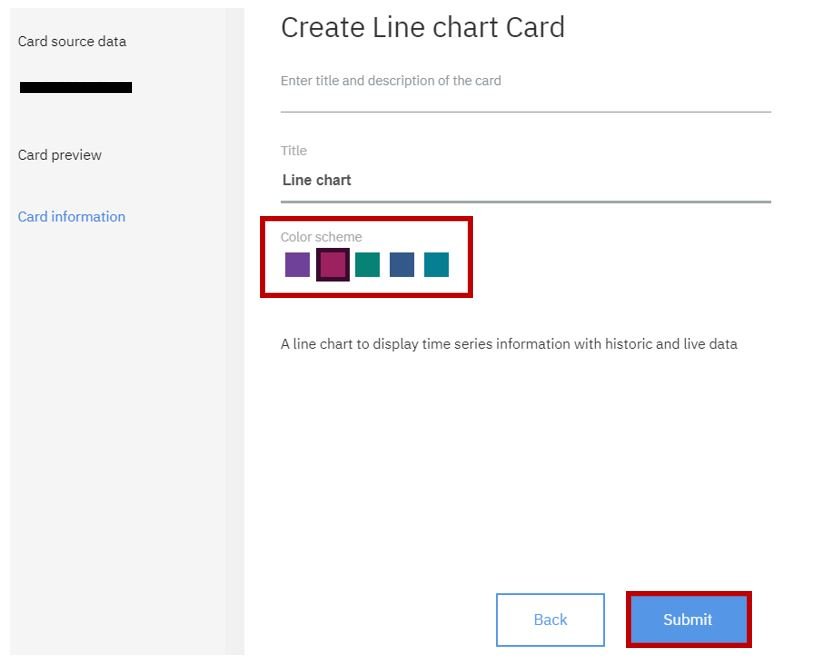
After choosing the colour scheme click ‘Submit’ for the changes to take place.
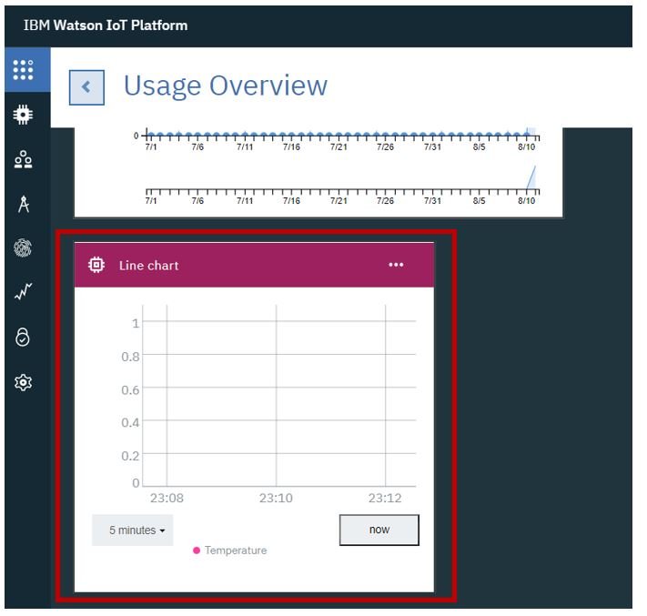
Now in the dashboard you will be able to view the line chart linked with the ESP32 device.
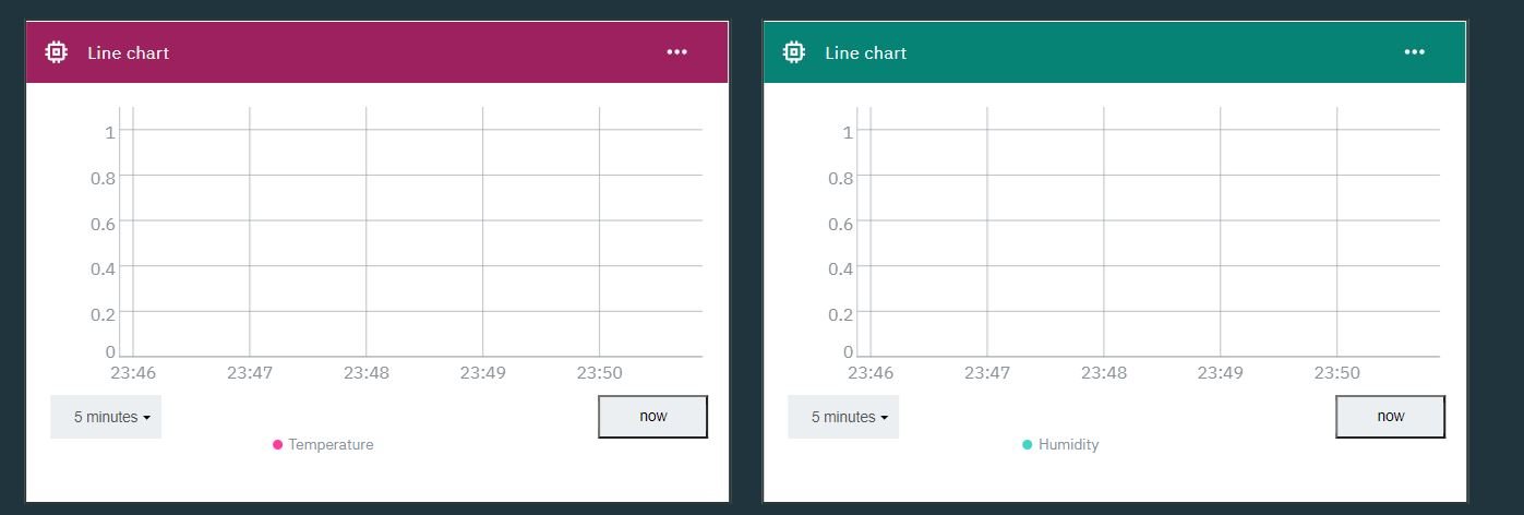
Similarly, follow the same steps to create a line graph for humidity readings. In the Connect data set section, set the event as ‘Data2’, property and name as Humidity, value as Number and unit as %.

After specifying all the details for the second line chart you will be able to view both graphs in the dashboard.
Connecting ESP32 with IBM Cloud
Now we will learn how to connect our ESP32 development board with the IBM cloud. Go to Security and then Connection security.

Now set the security level to ‘TLS Optional’ and click the Save button.

Setting up Arduino IDE
We will use Arduino IDE to program our ESP32 development board. Thus, you should have the latest version of Arduino IDE. Additionally, you also need to install the ESP32 plugin.
If your IDE does not have the plugin installed you can visit the link below: Installing ESP32 library in Arduino IDE and upload code.
Installing Libraries
For this project we will require two libraries:
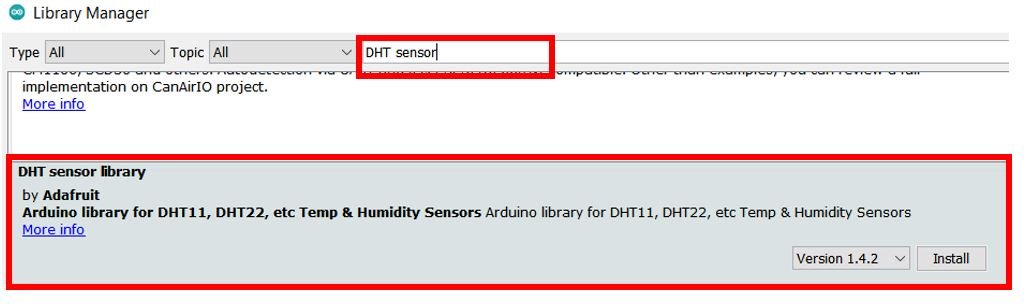
- DHT sensor library (As we are connecting the DHT22 sensor with ESP32 so we will have to use this library)
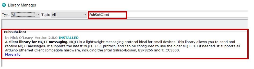
- PubSubClient library (We will use the MQTT protocol to send and receive sensor data that is why we need this library)
We will use the Library Manager in our Arduino IDE to install the latest versions of the libraries. Open your Arduino IDE and go to Sketch > Include Libraries > Manage Libraries. Type each library name in the search bar and install them both.
Arduino Sketch to find ESP32 Chip ID
Open your Arduino IDE and go to File > New to open a new file. Copy the code given below in that file and save it. This sketch will display the unique chip ID associated with your ESP32 board in the serial monitor.
uint64_t chipID;
void setup() {
 Serial.begin(115200);
}

void loop() {
 chipID=ESP.getEfuseMac();
Serial.printf("ESP32 Chip ID = %04X",(uint16_t)(chipID>>32));
Serial.printf("%08X\n",(uint32_t)chipID);

}
Make sure you choose the correct board and COM port before uploading your code to the board. Go to Tools > Board and select ESP32 Dev Module. Next, go to Tools > Port and select the appropriate port through which your board is connected. In this case, we are using the ESP32 development board which is connected to COM5.
Click on the upload button to upload the code into the ESP32 development board. Press its ENABLE button after the sketch has been uploaded.

In your Arduino IDE, open up the serial monitor and you will be able to see the unique chip ID of your ESP32 module.

Arduino Sketch (Sending DHT22 sensor data to IBM cloud)
Open your Arduino IDE and go to File > New to open a new file. Copy the code given below in that file and save it. You need to enter your network credentials. Additionally, you also have to provide your ID, the device type, device chip ID, and the authorization token which we saved previously.
#include <WiFi.h>
#include <WiFiClient.h>
#include <PubSubClient.h>
#include "DHT.h"

const char* ssid = "Your_SSID";
const char* password = "Your_Password";

#define DHTPIN 27
#define DHTTYPE DHT22
DHT dht(DHTPIN, DHTTYPE);

#define ID "tyw***"
#define DEVICE_TYPE "ESP32"
#define DEVICE_ID "84CA37B*****"
#define TOKEN "G!p_moIU(Omi11****"

char server[] = ID ".messaging.internetofthings.ibmcloud.com";
char publish_Topic1[] = "iot-2/evt/Data1/fmt/json";
char publish_Topic2[] = "iot-2/evt/Data2/fmt/json";
char authMethod[] = "use-token-auth";
char token[] = TOKEN;
char clientId[] = "d:" ID ":" DEVICE_TYPE ":" DEVICE_ID;

WiFiClient wifiClient;
PubSubClient client(server, 1883, NULL, wifiClient);

void setup() {
    Serial.begin(115200);
    dht.begin();
    Serial.println();
    WiFi.begin(ssid, password);
    while (WiFi.status() != WL_CONNECTED) {
      delay(500);
      Serial.print(".");
    }
    Serial.println("");
    Serial.println(WiFi.localIP());

    if (!client.connected()) {
        Serial.print("Reconnecting client to ");
        Serial.println(server);
        while (!client.connect(clientId, authMethod, token)) {
            Serial.print(".");
            delay(500);
        }
        Serial.println("Connected TO IBM IoT cloud!");
    }
}

long previous_message = 0;
void loop() {
    client.loop();
    long current = millis();
    if (current - previous_message > 3000) {
        previous_message = current;
         float hum = dht.readHumidity();
         float temp = dht.readTemperature();
         if (isnan(hum) || isnan(temp)  ){
    Serial.println(F("Failed to read from DHT sensor!"));
    return;
  }

  Serial.print("Temperature: ");
  Serial.print(temp);
  Serial.print("°C");
  Serial.print(" Humidity: ");
  Serial.print(hum);
  Serial.print("%");

        String payload = "{\"d\":{\"Name\":\"" DEVICE_ID "\"";
              payload += ",\"Temperature\":";
              payload += temp;
              payload += "}}";

        Serial.print("Sending payload: ");
        Serial.println(payload);

        if (client.publish(publish_Topic1, (char*) payload.c_str())) {
            Serial.println("Published successfully");
        } else {
            Serial.println("Failed");
        }
        String payload1 = "{\"d\":{\"Name\":\"" DEVICE_ID "\"";
              payload1 += ",\"Humidity\":";
              payload1 += hum;
              payload1 += "}}";
              Serial.print("Sending payload: ");
              Serial.println(payload1);
              Serial.println('\n');

         if (client.publish(publish_Topic2, (char*) payload1.c_str())) {
            Serial.println("Published successfully");
        } else {
            Serial.println("Failed");
        }
    }
}
How the Code Works?
Now, let us understand how each part of the code works.
Including Libraries
Firstly, we will include the relevant libraries which are necessary for this project. We are using four libraries: WiFi.h, WiFiClient.h, PubSubClient.h and DHT.h
First, we will include the Wi-Fi libraries. Then the other libraries that we previously installed (PubSubClient.h and DHT.h) and will be required for the MQTT protocol and the sensor functionality.
#include <WiFi.h>
#include <WiFiClient.h>
#include <PubSubClient.h>
#include "DHT.h"
Defining Network Credentials
Next, we will create two global parameters of type char which will hold the SSID and password. Replace the ‘*’ with your network credentials.
const char* ssid = "**********";
const char* password = "*********";
Defining DHT Sensor
The following lines of code will specify the type of DHT sensor and the GPIO pin of the ESP32 board which we will connect with the data pin of the sensor.
#define DHTPIN 27
#define DHTTYPE DHT22
DHT dht(DHTPIN, DHTTYPE);
Defining IBM Cloud credentials
Next, we will define the IBM cloud credentials which we will obtain from our IBM account. The first parameter is the user ID which is found at the top right hand side of the IBM Watson IoT Platform page, underneath your email address. Next is the device type and its chip ID named as ‘DEVICE_TYPE’ and ‘DEVICE_ID.’ We will also define the authorization token which we saved previously when we added our ESP32 device to the resource that we created. This we have defined as ‘TOKEN.’ Specify our own parameters in the variables given below.
#define ID "tyw***"
#define DEVICE_TYPE "ESP32"
#define DEVICE_ID "84CA37BD9***"
#define TOKEN "G!p_moIU(Omi1*****"
Now we will create several variables to properly connect with the IBM cloud and to send and receive data. First we will specify the server name which is the address where we will send our data. You do not need to change it. Next, we will define two topics where we will publish our sensor readings. This is because we have created two events Data1 and Data2 as we have to show both the temperature and humidity readings. Thus, publish_Topic1 will correspond to the event Data1 and publish_Topic2 will correspond to the event Data2. If you have named your events differently, remember to replace them accordingly. Next we will specify the token and the client ID as shown below. You do not need to change this here.
char server[] = ID ".messaging.internetofthings.ibmcloud.com";
char publish_Topic1[] = "iot-2/evt/Data1/fmt/json";
char publish_Topic2[] = "iot-2/evt/Data2/fmt/json";
char authMethod[] = "use-token-auth";
char token[] = TOKEN;
char clientId[] = "d:" ID ":" DEVICE_TYPE ":" DEVICE_ID;
Creating object
Next, create an object of WiFiClient called wifiClient which we will pass as a parameter inside PubSubClient cllient ().
WiFiClient wifiClient;
PubSubClient client(server, 1883, NULL, wifiClient);
setup()
Inside the setup() function, we will open a serial connection at a baud rate of 115200. Additionally, we will initiate the connection with the DHT sensor as well.
Serial.begin(115200);
dht.begin();
The following section of code will connect our ESP32 board with the local network whose network credentials we already specified above. We will use the WiFi.begin() function. The arguments will be the SSID and the password which we defined earlier in the code. After the connection will be established, the IP address of the ESP32 board will get printed on the serial monitor.
 WiFi.begin(ssid, password);
    while (WiFi.status() != WL_CONNECTED) {
      delay(500);
      Serial.print(".");
    }
    Serial.println("");
    Serial.println(WiFi.localIP());
Next, we will connect our ESP32 board with the IBM cloud platform in the lines given below. It will check for valid IBM credentials which we defined earlier. After a successful connection with the IBM cloud, the serial monitor will display “Connected to IBM IoT cloud!”
if (!client.connected()) {
        Serial.print("Reconnecting client to ");
        Serial.println(server);
        while (!client.connect(clientId, authMethod, token)) {
            Serial.print(".");
            delay(500);
        }
        Serial.println("Connected TO IBM IoT cloud!");
    }
loop()
In the infinite loop() we will obtain the temperature and humidity readings from the DHT22 sensor after every second and send them to the IBM cloud.
Firstly, through dht.readHumidity(), the humidity reading will get saved in the variable ‘hum.’ Likewise, for temperature, the sensor reading will get saved in the variable ‘temp.’
float hum = dht.readHumidity();
float temp = dht.readTemperature();
If the connection between the module and the sensor is incorrect or the values are not being accessed properly then an error message will be printed. This will help us in debugging our circuit or a possible issue in the initialization of the sensor.
if (isnan(hum) || isnan(temp)  ){
    Serial.println(F("Failed to read from DHT sensor!"));
    return;
}
Then, we will display these temperature and humidity readings on the serial monitor. Newer readings will continuously appear on the screen.
  Serial.print("Temperature: ");
  Serial.print(temp);
  Serial.print("°C");
  Serial.print(" Humidity: ");
  Serial.print(hum);
  Serial.print("%");
Next we will create a string variable named ‘payload’ to send the temperature readings to IBM cloud. This data will be published to the event ‘Data1.’
String payload = "{\"d\":{\"Name\":\"" DEVICE_ID "\"";
              payload += ",\"Temperature\":";
              payload += temp;
              payload += "}}";

        Serial.print("Sending payload: ");
        Serial.println(payload);

        if (client.publish(publish_Topic1, (char*) payload.c_str())) {
            Serial.println("Published successfully");
        } else {
            Serial.println("Failed");
        }
Likewise, to send humidity readings we will create another string named ‘payload1’ and send the data in it to the IBM cloud. We will be able to view it on the serial monitor after every reading gets successfully published.
String payload1 = "{\"d\":{\"Name\":\"" DEVICE_ID "\"";
              payload1 += ",\"Humidity\":";
              payload1 += hum;
              payload1 += "}}";
        Serial.print("Sending payload: ");
        Serial.println(payload1);
        Serial.println('\n');

         if (client.publish(publish_Topic2, (char*) payload1.c_str())) {
            Serial.println("Published successfully");
        } else {
            Serial.println("Failed");
        }
IBM Watson Cloud Demonstration
Choose the correct board and COM port before uploading your code to the board. Go to Tools > Board and select ESP32 Dev Module.

Next, go to Tools > Port and select the appropriate port through which your board is connected.

Click on the upload button to upload the code to your ESP32 development board.
After you have uploaded your code to the development board, press its ENABLE button.
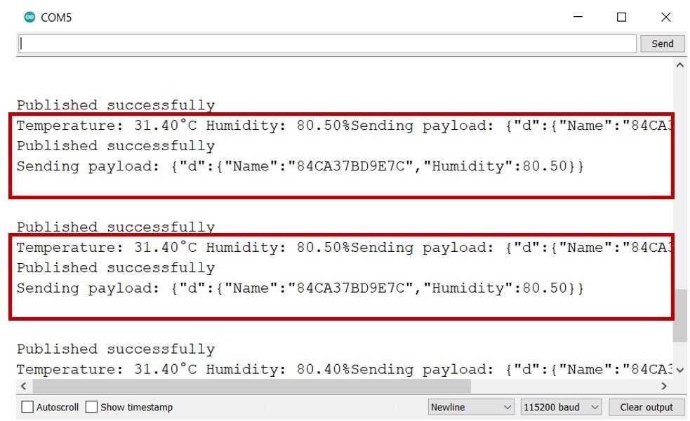
n your Arduino IDE, open up the serial monitor and you will be able to see the status of your WIFI connection and the IP address of your ESP module.
Shortly afterwards you will be able to view the temperature and humidity readings.
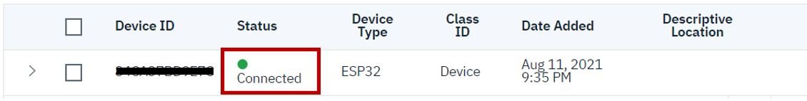
Open your IBM cloud platform and you will be able to see your ESP32 device get connected with the platform in the Devices section.
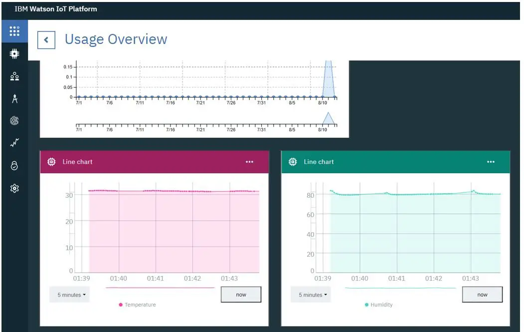
Now go to Boards and then Usage Overview. You will be able to view both the graphs display. The first one displays the temperature readings and the second one displays the humidity readings in real-time.
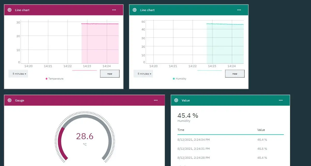
You can view the sensor readings in different charts as well (e.g. value or gauge) by creating another card just like we did before. Here we have also included gauge for temperature reading and value for humidity reading.
Conclusion
In conclusion, we have learned how to connect our ESP32 development board with the IBM Watson Cloud platform and send sensor data to it. You can visualize your data through various card options. IBM Watson is a very secure platform to build your IoT project. This was just a getting started guide to using IBM IoT cloud with ESP32.
To view more ESP32 related articles follow the links below:
- ESP32 Send Sensor Readings to Google Firebase and Build an Android app to display Data
- ESP32 Dual Core with FreeRTOS and Arduino IDE
- Getting Started with Arduino IoT Cloud with ESP32: Send Sensor Readings and Control Outputs
- ESP32 ESP-NOW Getting Started Tutorial with Arduino IDE
- ESP32 OTA (Over-The-Air) Updates using AsyncElegantOTA Library and Arduino IDE