Interfacing circuits with microcontrollers. In this article, I have discussed various elements and circuits interfacing with microcontrollers. These circuits are useful for those who want to work on embedded system projects but don’t have knowledge of electronics and embedded electronics. The following circuits will help you in the design of embedded system hardware circuits.
Transistor Interfacing Circuit
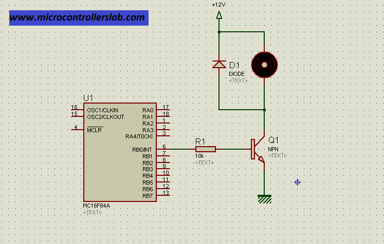
Figure below shows how to interface a transistor with a microcontroller. Diode D1 is used to avoid back EMF voltage in the case of an inductive load, such as a motor, as shown in the diagram below. In this circuit, transistor is used as a switch.
Relay Interface with Microcontroller
There are many applications where you need to interface a relay with a microcontroller, such as in high-power applications where you want to operate high-power loads like motors with the help of control signals from a microcontroller and power input from another power source. In such situations, we need a relay to separate the low-power control signals generating device from the high-power load, as shown in the figure below:
- 5V Dual Channel Relay Module Interfacing with Arduino
- Relay Module interfacing with pic16f877a microcontroller
- Microcontroller interfacing to relays using ULN2003
- Electromechanical Relays interfacing with microcontrollers
- Relay driver circuit using uln2003
- Control Relay Module Remotely with ESP32 Web Server and 220V Lamp
LED Interfacing with Microcontroller
I know, it is very easy to connect one LED with a microcontroller using a resistor, but one should be careful before connecting a current limiting resistor with an LED. Every microcontroller has a limit to sink and source current from its input/output pins. PIC microcontrollers can sink or source current up to 30mA. One should take care of current limits while selecting the resistor value. For example, if the current limit is 30mA and you want to calculate the resistor value, you can easily calculate it using Ohm’s law:
V = I * R;We know maximum input and output voltage from microcontroller pin is about 5 volt and already know value of current i.e 30mA. So by using above relation
R = V / I = 5 / 30 mA = 167.76So one can use standard resistor value of 200 ohm.
- LED Blinking using PIC Microcontroller with Examples
- STM32 Nucleo GPIO Pins with LED Blinking using STM32CubeIDE
- Raspberry Pi Pico GPIO Programming with MicroPython – LED Blinking Examples
- LED Blinking STM32 Nucleo with Arduino IDE – GPIO Pins
- STM32 Blue Pill GPIO Pins with STM32Cube IDE: LED Blinking Tutorial
- LED Blinking Tutorial STM32F4 Discovery Board – GPIO Pins with HAL Library
- LED Blinking using ESP8266 – NodeMCU
- GPIO pins of ESP32 – LED Blinking example
- How to use Input Output Ports 8051 Microcontroller: LED Blinking Example
- LED Blinking Using ATmega32 AVR Microcontroller
- LED Blinking with Arduino UNO R3
LCD Interfacing with Microcontroller
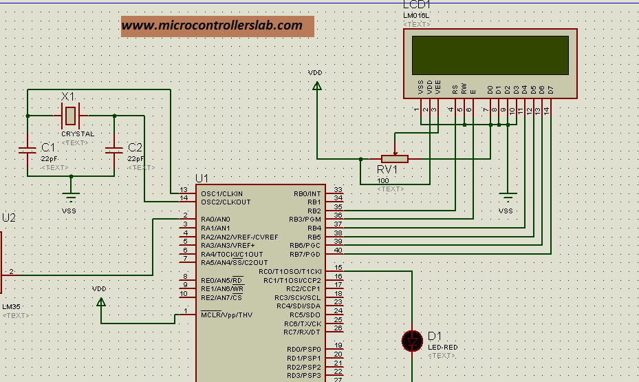
Diagram below shows a 16 * 2 LCD interfacing with a microcontroller. D0-D8 are data pins used to send data to the LCD. The rest of the pins are control pins used to perform various LCD commands like writing on the LCD, clearing the LCD screen, shifting the cursor to any position, and adjusting the text position on the LCD. A variable resistor is used to adjust the contrast/light of the LCD.
- I2C LCD interfacing with ESP32 and ESP8266 in Arduino IDE
- I2C LCD with STM32 Blue Pill using STM32CubeIDE
- I2C LCD with ESP32 and ESP8266 using MicroPython
- LCD Interfacing with TM4C123 Tiva LaunchPad – Keil uvision
- 16×2 LCD Interfacing with PIC Microcontroller – Examples
- LCD interfacing with MSP430 LaunchPad
- Interface LCD with 8051 Microcontroller
- LCD Interfacing with ATmega32 AVR Microcontroller
- 16×2 LCD Interfacing with Arduino – Explained with Example Codes
L293D Motor Driver IC Interfacing with Microcontroller
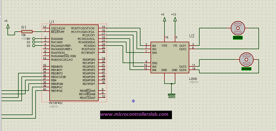
L293D is a DC motor driver IC. It serves the purpose of an H-bridge up to 1 ampere. It is used for the direction control of DC motors, especially in university-level robotics. The interfacing circuit is shown below:
- Arduino L293D Motor Driver Shield Control DC, Servo, and Stepper Motors
- DC Motor Speed and Direction Control with L293D Driver IC and Arduino
- DC Motor Control with LabVIEW and Arduino – Tutorial 3
- Control Stepper Motor with A4988 Driver Module and Arduino
if you need any interfacing circuit , feel free to comment on this post.


please provide me with schematics to interface uln2003,relay,lcd, max 232. plzz
check these articles for relay interfacing
http://microcontrollerslab.com/relay-driver-circuit-using-uln2003/
http://microcontrollerslab.com/relay-working-types/
check this on lcd interfacing with pic microcontroller
http://microcontrollerslab.com/lcd-interfacing-pic16f877a-microcontroller/
check this on serial communication using max232 and pic microcontroller
http://microcontrollerslab.com/serial-communication-using-pic16f877a-microcontroller/
I hope this helps you
kindly share the website and articles with your friends
Can you provide schematics for L293D Motor driver IC interfacing with microcontroller and with servo which is controlled by two push buttons left and right.
Thank You sir
can you provide schematics for L293D Motor driver IC interfacing with microcontroller and can you add servo motor which is control by push buttons left and right.
Thank you sir
This Content is valuable for microcontrollers.