This getting started guide on TTGO LoRa32 SX1276 OLED module explains pinout, pin configuration, features, how to use it with Arduino and how to install its library in Arduino IDE.

There is no ambiguity that the internet of things is the potential future. Different electronic companies launch various devices almost every other day in the market. These smart appliances and IoT technology have compelled industrial systems as well as consumer level.
Recommended Components
The following components are used in this project or are helpful for building it with the ESP32.
| Component | How it’s used in this project | Buy on Amazon |
|---|---|---|
| ESP32 Development Board (DevKit V1) | The ESP32 chip is the core of the TTGO LoRa32 board used in this guide. | Check Price |
| Micro USB Cable | Connects the board to your computer for programming and power. | Check Price |
| Breadboard | Holds the board and any added components while testing. | Check Price |
| Jumper Wires | Connect the board to other parts on the breadboard. | Check Price |
As an Amazon Associate we earn from qualifying purchases. Prices and availability are accurate as of the date/time indicated and are subject to change.
TTGO LoRa32 SX1276 OLED Introduction
The TTGO LoRA SX1276 OLED Board is a device introduced by Semtech. The module is an example of a LoRa device. It works with a long-range radio frequency band to transmit or receive small data packets. This leads to less interference and prevents signal loss. Different regions are assigned with specific LoRa bands. LoRa has a greater frequency range than cellular networks and can be used by the public, private and private sectors. This technology has quite made an impact in the world of artificial intelligence and IoT.

Components
The board is a complete and perfect module for intelligent systems. The module consists of Espressif ESP32, Semtech SX1276 an OLED display. It is integrated with WiFi, Bluetooth and comes with an antenna. The SX1276 OLED module has high-resolution ADCs, SPI, I2C, and UART protocols for information communication. It is embedded with 32-bits of LX6 processor and an SRAM of 540 KB. The module is provided with an inbuilt battery connector to provide supply and a USB connector to associate the module directly to the personal computer for coding.
TTGO LoRa32 SX1276 OLED Pinout
The module is integrated with voltage regulators, pull up resistors, coupling capacitors and a power LEDThe following diagram shows the pinout of the TTGO LoRA SX1276 OLED Board:

Pin Configuration
This section describes the pinout of the TTGO LoRA SX1276 OLED Board. The TTGO LoRA SX1276 OLED Board has a total of 36 pins. The pin configuration is explained for a better knowledge of their multiple characteristics:
GPIO Pins
The module has 28 multipurpose GPIO pins out of 36 pins exposed on the board. The pins can be used as input/output pins if their other respective functions are not in use.
SPX1276 SPI Pins
The SPX1276 chips are internally connected to ESP32 GPIO pins. The data is serially communicate between two chipsets through the SPI protocol.
| SPX1276 Pins | ESP32 |
|---|---|
| MISO | GPIO19 |
| MOSI | GPIO27 |
| SCK | GPIO5 |
| CS | GPIO18 |
| IRQ | GPIO26 |
| RST | GPIO14 |
OLED display connections
The inbuilt OLED display is connected to ESP32 for I2C Communication purposes. It will display the information obtained after processing onto the screen.
| OLED display Pins | ESP32 |
| SDA | GPIO15 |
| SCL | GPIO4 |
| RST | GPIO16 |
Power Supply pins
The module is provided with 8 power supply pins to provide input voltage to all the peripherals placed on the board. The module can be powered through lithium batteries. It has a battery circuit and a 2-pin JST header.
You can read more about ESP32 Pinout here: ESP32 Pinout
Other Peripherals
CP2102 Connector
The module has a CP2102 USB connector. With the help of this, the module can be programmed directly. It can energize the module as well.
PRG and RST push buttons
The board is facilitated to reset itself through an RST button. The module supports flashing mode as well. And for that, the PRG(BOOT) button should be pressed.
Antenna
The Ipex printed on the board is to connect the antenna for the transmission and reception. If not used, it would damage the board.
TTGO SX1276 LoRa 32 OLED Board Specifications
The technicals and specifications of this extremely handy module are listed below:
| Feature | Availability |
|---|---|
| Chip | ESP32 |
| Module | SX1279 |
| Processor | 32-bit LX6 |
| Flash memory | QSPI 4 MB |
| SRAM | 540 KB |
| Battery input Voltage | 3.7 Volts – 4.2 Volts |
| JST Connector | 2, 1.25mm pins |
| Operating Current | 500 mA |
| USB Connector | Yes |
| Buttons | PRG & Reset |
| PRG mode | Yes |
| Reset mode | Yes |
| USB to UART | CP2102 |
| Communication Interfaces | UART, SPI, SDIO, I2C, PWM, I2S, ADC, DAC, Cap Sensor |
| Clock Frequency | 40 MHz |
| Operating Voltage | 2.7Volts – 3.6 Volts |
| Sleep current | 600uA (max) |
| Operating Temperature | -40℃ to 85℃ |
| OLED screen display | OLED 0.96 Inch |
| Package Dimensions | 53.07mm x 25.32mm x 7.5mm |
WiFi & Bluetooth Specifications
| Feature | Availability |
|---|---|
| Wifi standard | FCC/CE-RED/IC/TELEC/KCC/SRRC/NCC(esp32 chip) |
| Wifi Protocol | 802.11 b/g/n(802.11n,speed up to150Mbps)A-MPDU and A-MSDU polymerization,support 0.4μS Protection interval |
| Bandwidth | 2.4GHz~2.5GHz(2400M~2483.5M) |
| Power transmission | 22dBm |
| Communication range | 300m |
| Protocol | bluetooth v4.2BR/EDR and BLE standard |
| RF frequency | With -97dBm sensitivity NZIF receiver Class-1,Class-2&Class-3 emitter AFH |
| Audio frequency | CVSD & SBC audio frequency |
| Wi-Fi Mode | Station/SoftAP/SoftAP+Station/P2P |
| Security mechanism | WPA/WPA2/WPA2-Enterprise/WPS |
| Encryption Type | AES/RSA/ECC/SHA |
| OS | FreeRTOS |
| Networking protocol | IPv4, IPv6, SSL, TCP/UDP/HTTP/FTP/MQTT |
Working of SX1276 LoRa Board
The board works using LoRa technology and is a big thing in the Internet of Things world. LoRa is a low-power, long-range spread spectrum technique that uses unlicensed radio frequencies all over the world. Different megahertz frequency ranges are allotted to different regions for the data transmission.
- Europe LoRa RF range: 433 MHz, 868 MHz
- Australia and North America Lora RF range: 915 MHz
- India LoRa RF range: 865 MHz – 867 MHz
- Asia LoRa RF range: 923 MHz
Semtech Lora Board works in a similar fashion. It transmits and receives data packets up to the range of 1 km using the LoRa bands. It can transmit small data with minimum interference. The module is incorporated with ESP32 for the processing and the data is displayed on the embedded OLED display. The module does not require a microcontroller. Instead, CP102 USB to UART Bridge is integrated to get connected to the PC and programmed directly.
Install Arduino Libraries for TTGO LoRa SX1276 OLED Board
This section shows how to program and write code for TTGO LoRa SX1276 OLED Board. The board has a USB connector that is connected directly to the PC system to burn the code. The SX1276 LoRa module is programmable through Arduino IDE as it has ESP32 add ons and LoRa compatible libraries for the execution.
Install ESP32 Library in Arduino IDE
As the SX1276 is embedded with ESP32 IC, we need to first install the ESP-32 add-on to the Arduino IDE. Before this, one must have the latest version of Arduino IDE otherwise it won’t be compatible.
The link https://dl.espressif.com/dl/package_esp32_index.json should be added to the Arduino IDE. For this purpose follow these steps as described:
- Click File>Preferences> “Additional Board Manager URLs”> Paste the link>Ok
The next step is to install the board. For this purpose go to
- Tools>Board>Arduino UNO/Genuino>Board Manager
- Search the board by typing “ESP32” in the search panel. Click “Install” and IDE starts to install the board. After some time the software is ready to be used.
You can read this in-depth guide to see how to install ESP32 in Arduino IDE:
You can also watch this video lecture:
Install OLED and LoRa Library
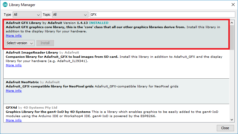
To make the OLED screen work, we need to install OLED libraries compatible with ESP32. This program is including two OLED libraries i.e. Adafruit_SSD1306 and Adafruit_GFX library. These specifically written libraries are helpful in the interfacing of OLED displays. After opening the Arduino IDE, follow the provided steps to install the libraries:
Go to Sketch > Include library > Manage library > Library manager. Next search the SSD1306 library by Adafruit and install it to the software.

Similarly, type GFX in the search box and install it too.
Again, follow these above steps to install the LoRa library. The LoRa library used in the given code is arduino_LoRa by sandeep mistry. After installation completion, restart the Arduino software and it is ready to use.
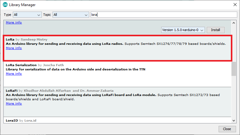
After intalling libraries, close your Arduino IDE and open it again.
TTGO LoRa32 SX1276 OLED Arduino Code
These codes are about two SX1276 LoRa Boards communicating with each other through LoRa frequencies. One SX1276 LoRa board acts as a transmitter and the other as a receiver. The Arduino sketches for both transmitter and receiver boards are provided below:
Transmitter Code
//Libraries for LoRa
#include <SPI.h>
#include <LoRa.h>

//Libraries for OLED Display
#include <Wire.h>
#include <Adafruit_GFX.h>
#include <Adafruit_SSD1306.h>

//define the pins used by the LoRa transceiver module
#define SCK 5
#define MISO 19
#define MOSI 27
#define SS 18
#define RST 14
#define DIO0 26

//433E6 for Asia
//866E6 for Europe
//915E6 for North America
#define BAND 866E6

//OLED pins
#define OLED_SDA 4
#define OLED_SCL 15
#define OLED_RST 16
#define SCREEN_WIDTH 128 // OLED display width, in pixels
#define SCREEN_HEIGHT 64 // OLED display height, in pixels

//packet packet_counter
int packet_counter = 0;

Adafruit_SSD1306 display(SCREEN_WIDTH, SCREEN_HEIGHT, &Wire, OLED_RST);

void setup() {
  //initialize Serial Monitor
  Serial.begin(115200);

  //reset OLED display via software
  pinMode(OLED_RST, OUTPUT);
  digitalWrite(OLED_RST, LOW);
  delay(20);
  digitalWrite(OLED_RST, HIGH);

  //initialize OLED
  Wire.begin(OLED_SDA, OLED_SCL);
  if(!display.begin(SSD1306_SWITCHCAPVCC, 0x3c, false, false)) { // Address 0x3C for 128x32
    Serial.println(F("SSD1306 allocation failed"));
    for(;;); // Don't proceed, loop forever
  }

  display.clearDisplay();
  display.setTextColor(WHITE);
  display.setTextSize(1);
  display.setCursor(0,0);
  display.print("LORA SENDER ");
  display.display();

  Serial.println("LoRa Sender Test");

  //SPI LoRa pins
  SPI.begin(SCK, MISO, MOSI, SS);
  //setup LoRa transceiver module
  LoRa.setPins(SS, RST, DIO0);

  if (!LoRa.begin(BAND)) {
    Serial.println("Starting LoRa failed!");
    while (1);
  }
  Serial.println("LoRa Initializing OK!");
  display.setCursor(0,10);
  display.print("LoRa Initializing OK!");
  display.display();
  delay(2000);
}

void loop() {

  Serial.print("Sending packet: ");
  Serial.println(packet_counter);

  //Send LoRa packet to receiver
  LoRa.beginPacket();
  LoRa.print("hello ");
  LoRa.print(packet_counter);
  LoRa.endPacket();

  display.clearDisplay();
  display.setCursor(0,0);
  display.println("LORA SENDER");
  display.setCursor(0,20);
  display.setTextSize(1);
  display.print("LoRa packet sent.");
  display.setCursor(0,30);
  display.print("packet_counter:");
  display.setCursor(50,30);
  display.print(packet_counter);
  display.display();

  packet_counter++;

  delay(10000);
}
Receiver Code
//Libraries for LoRa
#include <SPI.h>
#include <LoRa.h>

//Libraries for OLED Display
#include <Wire.h>
#include <Adafruit_GFX.h>
#include <Adafruit_SSD1306.h>

//define the pins used by the LoRa transceiver module
#define SCK 5
#define MISO 19
#define MOSI 27
#define SS 18
#define RST 14
#define DIO0 26

//433E6 for Asia
//866E6 for Europe
//915E6 for North America
#define BAND 866E6

//OLED pins
#define OLED_SDA 4
#define OLED_SCL 15
#define OLED_RST 16
#define SCREEN_WIDTH 128 // OLED display width, in pixels
#define SCREEN_HEIGHT 64 // OLED display height, in pixels

Adafruit_SSD1306 display(SCREEN_WIDTH, SCREEN_HEIGHT, &Wire, OLED_RST);

String LoRa_Data;

void setup() {
  //initialize Serial Monitor
  Serial.begin(115200);

  //reset OLED display via software
  pinMode(OLED_RST, OUTPUT);
  digitalWrite(OLED_RST, LOW);
  delay(20);
  digitalWrite(OLED_RST, HIGH);

  //initialize OLED
  Wire.begin(OLED_SDA, OLED_SCL);
  if(!display.begin(SSD1306_SWITCHCAPVCC, 0x3c, false, false)) { // Address 0x3C for 128x32
    Serial.println(F("SSD1306 allocation failed"));
    for(;;); // Don't proceed, loop forever
  }

  display.clearDisplay();
  display.setTextColor(WHITE);
  display.setTextSize(1);
  display.setCursor(0,0);
  display.print("LORA RECEIVER ");
  display.display();

  Serial.println("LoRa Receiver Test");

  //SPI LoRa pins
  SPI.begin(SCK, MISO, MOSI, SS);
  //setup LoRa transceiver module
  LoRa.setPins(SS, RST, DIO0);

  if (!LoRa.begin(BAND)) {
    Serial.println("Starting LoRa failed!");
    while (1);
  }
  Serial.println("LoRa Initializing OK!");
  display.setCursor(0,10);
  display.println("LoRa Initializing OK!");
  display.display();
}

void loop() {

  //try to parse packet
  int packetSize = LoRa.parsePacket();
  if (packetSize) {
    //received a packet
    Serial.print("Received packet ");

    //read packet
    while (LoRa.available()) {
      LoRa_Data = LoRa.readString();
      Serial.print(LoRa_Data);
    }

    //print RSSI of packet
    int rssi = LoRa.packetRssi();
    Serial.print(" with RSSI ");
    Serial.println(rssi);

   // Dsiplay information
   display.clearDisplay();
   display.setCursor(0,0);
   display.print("LORA RECEIVER");
   display.setCursor(0,20);
   display.print("Received packet:");
   display.setCursor(0,30);
   display.print(LoRa_Data);
   display.setCursor(0,40);
   display.print("RSSI:");
   display.setCursor(30,40);
   display.print(rssi);
   display.display();
  }
}
How does the code work?
For clarity of the concepts, the code is explained in snippets.
Include libraries
The typical first step is to include concerning libraries In this sketch, “SPI.h, Wire.h, LoRa.h, Adafruit_SFX.h and Adafruit_SSD1306” for interfacing the LoRa chip, OLED screens, and error-free execution of serial information.
Defining pins
Next step is to define pin connections. We have defined the LoRa receptor and transmitter pins for the SPI interface.
It is important to select the LoRa frequency to make the transmission between the LoRa modules. Every region is permitted with specific LoRa bandwidth. Make sure to uncomment the LoRa frequency depending upon the location.
The SDA, SCL, and RST of the OLED are defined along with the display dimensions in terms of pixels. The screen width is set to 128 pixels and the height of the OLED screen is set to 64 pixels.
An Adafruit OLED object named as the display is created. Furthermore, a variable called counter is made to keep the check of packets sent to the receiver LoRa module.
void Setup and for loop
The void setup block is responsible for resetting the module manually to use the OLED. This is accomplished by lowering and then setting the RST pin high again with a delay of 20 milliseconds via Arduino software. Besides, the 12C Bus of the OLED is defined. The object display is initialized with some parameters that include OLED’s address i.e 0x3c and two false arguments. These false arguments make sure that the OLED library uses the defined I2C pins(GPIO4 and GPIO15) instead of the default ones in the library.
The forever loops check the parameters of the object display. If it is unable to connect to the OLED then the execution flow will remain in this loop and shows a message “SSD1306 allocation not found.” on the serial monitor.
It is a must to configure the OLED display settings before showing any text. The text font, color, and position of the cursor are set using the provided commands. Following that, the serial monitor is initialized with a baud rate of 115200bps and displays the introductory messages.
LoRa object initialization
Now, the SPI interface pins of the LoRa integrated circuit are defined and the LoRa transceiver module is set up. The bandwidth is passed as an argument to the LoRa object. If the frequency matches the defined bandwidth, an accomplishment message is displayed otherwise the serial monitor shows up a failure message.
void loop
This block is the body of the loop. The messages are sent in the form of packets to the receiver LoRa module. A packet is initialized using LoRa.beginPacket() and terminated using LoRa.beginPacket(). The data to be transmitted is written between these statements using the LoRa.printPacket()function. We are sending a “hello” message and counter value in a packet from one board to another wirelessly. The number of times the packet is sent, the counter variable increments by unity. The loop is executed after every 1000 milliseconds.
Changes in receiver code
Little alterations are made here and there in the code accordingly.
LoRadata: To store the data received by the module, the variable LoRadata is created.
Receiver’s void loop
The reception of a packet is checked using the function called parsePacket() and reports the packet size. If a packet is received, a message is displayed on the monitor. The data is interpreted through LoRa.readString() and is placed in the LoRadata variable. Meanwhile the Rssi value is also obtained using Lora.packetRssi() into rssi. The packet information and the rssi value are then displayed with the execution of instructions.
TTGO LoRa32 SX1276 Applications
- IoTs
- Home Automation projects
- Robotics
- Smart DIY Projects
- Temperature and moisture monitoring
- Point to point communication
- Smart consumer electronics
- Security Systems
- Intelligent Industrial applications
- Smart Agriculture
Hello, could you also provide the library for LoRa32 SX1276 on Proteus?