In this user guide, you will learn how to use the Arduino IoT cloud using an ESP32 module. Through this software, we’ll show you how to create your very own IoT project through which you will be able to control the onboard LED of your ESP32 board. Not only that, but we will also create a dashboard that will display the current temperature and humidity readings. Most importantly, you can access the dashboard from anywhere in the world.
Any appropriate sensor can be used such as DS18B20, BME680, LM35, and MPU6050 but for this project, we will use a DHT11/dhr22 sensor which is used to measure temperature and humidity. Through Arduino IoT cloud you will be able to control both the ESP32 onboard LED and sensor readings using your mobile as well as on the web dashboard.
Previously, we controlled the ESP module’s outputs through applications such as Telegram, Google Firebase, and Blynk App. You can view the tutorials by accessing the links below:
- Telegram ESP32 and ESP8266: Control GPIOs and LEDs using Arduino IDE
- Google Firebase: Control ESP32 Outputs with Arduino IDE
- Control ESP32 Outputs using Blynk App and Arduino IDE
We also built our personal ESP32 IoT application by using Google Firebase and MIT App Inventor. This displayed DHT11/DHT22 sensor readings on the Andriod application:
This time we will look into another great application Arduino IoT Cloud through which we will control the ESP32’s output as well as connect it with a DHT11 sensor to monitor sensor readings.
We will require the following for our project:
Hardware Required:
- ESP32
- DHT11 Sensor
- Connecting Wires
- Breadboard
Software Required:
- Arduino IoT Cloud
- Arduino Create Agent
Introduction to DHT11 sensor
DHT11 sensor is used to measure the temperature and humidity. It has a resistive humidity sensing component and a negative temperature coefficient (NTC). An 8-bit MCU is also connected in it which is responsible for its fast response. It is very inexpensive but it gives values of both temperature and humidity simultaneously. DHT sensors are pre-calibrated. We can directly connect them with ESP32/ESP8266 to obtain sensor output reading. They are internally composed of a humidity sensing sensor and a thermistor. These two components measure humidity and temperature.
Features of DHT11
- Humidity range: from 20 to 90% RH
- Temperature range: from 0 – 50 C
- Signal transmission range: ~20 m
- Inexpensive
- Fast response and it is also durable
For more information regarding DHT11, you can have a look at the articles listed below:
- DHT11 interfacing with arduino and weather station
- MicroPython: DHT11/DHT22 Web Server with ESP32/ESP8266 (Weather Station)
- Interface DHT11/DHT22 with ESP32 and display values on Web Server
- DHT11 sensor interfacing with pic microcontroller
Connecting DHT11 sensor with the ESP32 development board
The connection of DHT11 with the ESP32 board is very easy. Originally, the DHT sensor consists of four pins. Where the first pin is the VCC pin, the second is the data pin which has to be connected with an additional 10k ohm resistor, the third is the un-used pin and the fourth pin the ground pin. However, on the DHT modules, only three pins are exposed to the pinout of the module and10k ohm pull-up resistor is internally connected to pin 2. We will be using the module in our project.
Connect the ground and the VCC of the DHT11 sensor module to the ground and 3.3V pin of ESP32. Then connect the data pin of the DHT11 sensor module to any appropriate output pin of the board. We have used GPIO14 in this case.
Follow the schematic diagram below for the ESP32 module and connect them accordingly.
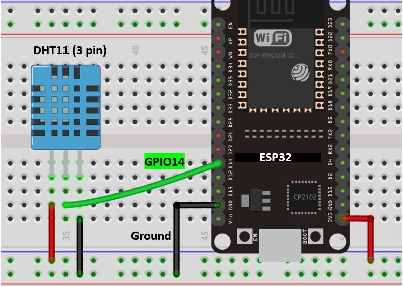
Vin is connected with a 3.3V pin on the module and both the ESP board and the sensor module is commonly grounded.
Arduino IoT Cloud
Arduino IoT cloud is a free application where the user can build software to control microcontrollers such as Raspberry Pi, Arduino, and ESP8266 NodeMCU, etc. It allows the users to create connected circuits using microcontrollers which can be easily monitored through an engaging user interface. Real-time data exchange is done easily and securely. For the user, it becomes extremely interactive and easy to use this application to build IoT projects from anywhere over the internet. Only the Arduino IoT cloud application and a steady internet connection in your device (smartphone, laptop, tablet, etc.) are a requirement. No need to install additional libraries.
Getting Started with Arduino IoT Cloud
Working in the Arduino IoT cloud is very simple and easy. Thus, follow the steps given below to successfully build your very first project.
Signing in
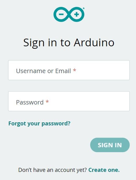
Firstly, type https://www.arduino.cc/ in your browser search tab and press enter. This will open the following homepage of Arduino IOT Cloud. Although this application is free to use but you will have to create an Arduino account. Click Sign in.

If you already have an Arduino account enter the username and password. Otherwise, create a new account to proceed further.
After you have successfully signed in, you will be redirected to the main page. Now click the dotted box as highlighted below

Select ‘IoT Cloud.’

Creating Thing
A new window will open up. Now we will have to create a ‘thing.’ This will define the device, Wi-Fi network and will generate variables accordingly which we will be able to control. Click on ‘Create Thing.’

This will open a new screen which will be our Thing overview. As you can see, we will set the tile of our project, variables, device and network settings.

Adding Variables
Our project involves three variables one for the LED output, one for temperature and another for humidity. We will create each variable individually. First, we will create the variable for the LED output. Go to the variables section and click ‘Add variable.’ The following section will open up. Add details for the LED output variable like name, variable type, variable permission and variable update policy.
We specified the variable details as follow:
- Name: LED_output (You can use any other name of your choice)
- Variable type: Light
- Variable Permission: read and write (as LED will be configured as an output that we have to read/write data)
- Var Update Policy: On change (we want the variable to update whenever a change is detected)

After specifying all the details, click ‘Add variable.’ In the Thing overview, this new variable will get generated.

Now we will create two more variables one for humidity and another for temperature. Below you can view the details which we have specified for these two variables. Notice that both of these are sensor readings thus variable permission will be checked as read-only.


You can view all the three variables in the Thing overview as shown below:

This is how you can add variables for your project.
Selecting Device
Now, we will link a device to the Thing. Go to Device > Select Device.

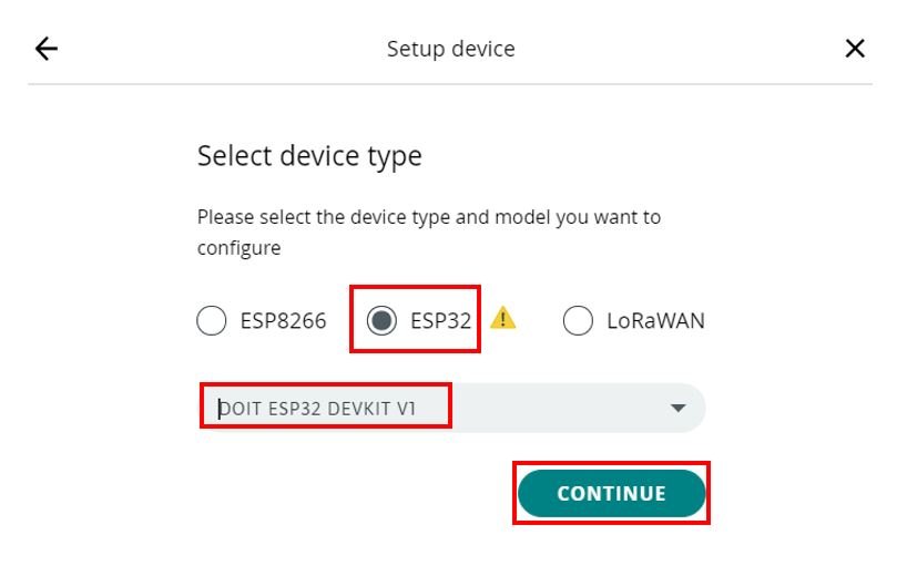
We have two options. Either to select Arduino device or third-party device. As we are using the ESP32 development board thus, we will select ‘third party device.’

Next, select device type. We will choose ‘ESP32’ and the model as ‘DOIT ESP32 DEVKIT V1’. Then click ‘Continue.’
Then we will be prompted to give a name to our device. You can use any preferred name.

Now, you will receive the credentials which will include the device id and the secret key. Copy and save both of them. We will use them later on. Keep it a secret and do not share it with anyone or your project security will be compromised. After saving the credentials, click ‘Continue.’

Press the ‘Done’ button. Thus, we have successfully set up our ESP32 development board for the project.

Providing Network credentials
Now, the last step in the Thing overview is to set up a Wi-Fi connection. Go to the Network section and click ‘configure.’

Enter the following details to configure the network. You will have to provide the SSID and the password of your Wi-Fi connection. Additionally, you will also need to specify the secret key which we saved previously. After adding the details, click ‘Save.’

All these three configurations (adding variables, configuring device and network) which we made will automatically get generated in a sketch file. We have completed the process to configure the device. At this point, our Thing window will look like this:

Building Dashboard
Now let us move to the next part where we will build the dashboard. At the top of the window, you will find ‘Dashboard.’ Click it.

The following appears on the screen. Click ‘Build Dashboard.’

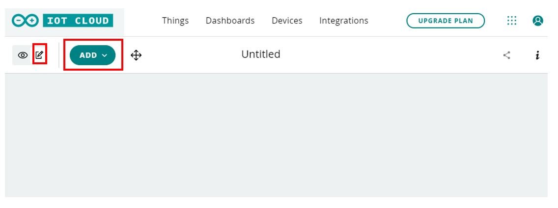
Click the pencil icon highlighted below. The ‘ADD’ button will pop up. Click on it.
LED Widget
This will open up a list from which we can choose the widgets we want to add to our dashboard. You can search for your required widget in the search tab or look through the list. Firstly, we will choose a switch.
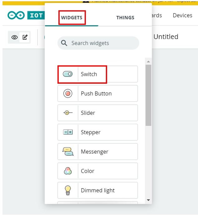
Click the switch widget and the following appears. Give a name to the switch. In our case we are calling it ‘LED.’ Then link it with a variable by clicking ‘Link Variable.’

This will display the variables which we previously created in the Thing. Click the ‘LED_output’ variable and then click ‘Link Variable’ to proceed further.

Click ‘Done’ to create the widget with the given attributes as shown below:

We have successfully configured the first widget.
Now, we will add more widgets to monitor humidity and temperature.
Humidity & Temperature Widgets
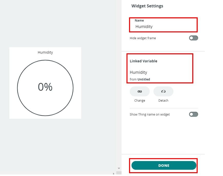
For humidity readings go to Add > Widgets > Percentage and click it.

Then we will give this widget the name ‘Humidity’ and link it with the humidity variable. Click ‘Done’ to finish creating the second widget.
Similarly, we will create a widget to monitor temperature readings. Go to Add > Widgets > Gauge and click it.

Then we will give this widget the name ‘Temperature’ and link it with the temperature variable. You can also define the range but we will keep it as default for now. Click ‘Done’ to finish creating the third widget.

We can add another widget to display the temperature readings in a graph. Go to Add > Widgets > Charts

Then we will give this widget the name ‘Temperature’ and link it with the temperature variable. You can also choose the type of chart (spline/line) but we will keep it as default for now. Click ‘Done’ to finish creating the widget.

We have successfully configured the widgets on the dashboard. The dashboard will look like this with the four widgets which we created:

Sketch
Now as we have configured our device and dashboard, let us look into the sketch to program our ESP32 board. Go to Things, select the Thing overview which we created (Untitled) and then go to Sketch. This will open a sketch generated from our Thing which we can modify for our project. The three variables which we created are already defined with the necessary libraries and functions.

We will include additional lines of code inside this sketch to incorporate the logic functionality.
Adding logic for onboard LED
For the Onboard LED functionality, we will add the following lines.
setup()
The onboard LED of ESP32 is connected to GPIO2. Inside the setup() function we will include the following line to configure GPIO2 as an output pin:
pinMode(2,OUTPUT);onLEDOutputChange()
In the onLEDOutputChange() function include the following lines. Whenever the state of the LED will be 1 i.e., HIGH the onboard LED will turn ON otherwise it will turn OFF. This will be achieved by calling the digitalWrite() function. We will pass the first parameter as ‘2’ and the second as ‘HIGH’ or ‘LOW’ accordingly.
void onLEDOutputChange() {
   if (lED_output == 1)
   {
   digitalWrite(2,HIGH);
   }
   else{
     digitalWrite(2,LOW);
   }
}
Adding logic for temperature and humidity sensor readings
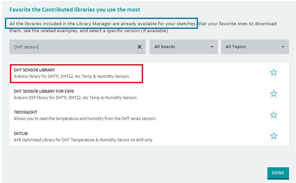
To access temperature/humidity sensor readings from the DHT11 sensor we will have to include an additional library. One of the greatest features of the Arduino IoT cloud is that most of the libraries are already available and you do not need to import them. For this project, we require the DHT sensor library. To see whether Arduino cloud already has that particular library installed, follow the steps below.
First, click ‘open full editor.’

The following window will open.

Go to Libraries > Library Manager. Type DHT sensor library. You will see that it is already available for all the sketches created in the Arduino cloud. Thus, we do not need to import it.
Now, we will carry on modifying our sketch. Include the following lines of code for the proper functionality of the sensor.
Including Library
First, we will include the DHT sensor library as we want to access sensor readings from DHT11 connected with our ESP32 board.
#include "DHT.h"Defining DHT Sensor
The following lines of code will specify the type of DHT sensor and the GPIO pin of the ESP32 board which we will connect with the data pin of the sensor. In this project, we are using the DHT11 sensor and connecting its data pin with GPIO14 of the ESP32 module. You can use any appropriate pin.
#define DHTPIN 14
#define DHTTYPE DHT11
DHT dht(DHTPIN, DHTTYPE);
setup()
Inside the setup() function, we will initiate the connection with the DHT sensor by calling the begin() function on the dht object.
dht.begin();loop()
Inside the loop() function we will obtain the sensor readings and handle them accordingly. Firstly, through dht.readHumidity(), the sensor reading will get saved in the variable ‘hum.’ Likewise, for temperature, the sensor reading will get saved in the variable ‘temp.’
float hum = dht.readHumidity();
float temp = dht.readTemperature();
If the connection between the module and the sensor is incorrect or the values are not being accessed properly then an error message will be printed. This will help us in debugging our circuit or a possible issue in the initialization of the sensor.
if (isnan(hum) || isnan(temp)  ){
    Serial.println(F("Failed to read from DHT sensor!"));
    return;
  }
Then, we also want to update the sensor variables temperature and humidity which we created in Things so that our dashboard displays updated sensor data. We will save the individual sensor readings accessed from the sensor temp and hum into temperature and humidity respectively.
humidity = hum;
temperature = temp;
Additionally, we will display these temperature and humidity readings on the serial monitor. Newer readings will continuously appear on the serial monitor as well as on the dashboard after a delay of 1 second.
  Serial.print("Temperature: ");
  Serial.print(temp);
  Serial.print("°C");
  Serial.print(" Humidity: ");
  Serial.print(hum);
  Serial.print("%");
  Serial.println();
  delay(1000);
We have successfully added the additional lines of code to incorporate the led and sensor readings functionality. You can take a look at the completed sketch below:
Sketch generated by the Arduino IoT Cloud Thing "Untitled"
  https://create.arduino.cc/cloud/things/9b7f6c70-bc31-462c-9814-30c316e57b42

  Arduino IoT Cloud Variables description

  The following variables are automatically generated and updated when changes are made to the Thing

  CloudLight lED_output;
  CloudTemperatureSensor temperature;
  CloudRelativeHumidity humidity;

  Variables which are marked as READ/WRITE in the Cloud Thing will also have functions
  which are called when their values are changed from the Dashboard.
  These functions are generated with the Thing and added at the end of this sketch.
*/

#include "thingProperties.h"
#include "DHT.h"

#define DHTPIN 14

#define DHTTYPE DHT11
DHT dht(DHTPIN, DHTTYPE);

void setup() {
  // Initialize serial and wait for port to open:
  Serial.begin(9600);
  dht.begin();
  pinMode(2,OUTPUT);
  // This delay gives the chance to wait for a Serial Monitor without blocking if none is found
  delay(1500);

  // Defined in thingProperties.h
  initProperties();

  // Connect to Arduino IoT Cloud
  ArduinoCloud.begin(ArduinoIoTPreferredConnection);

  /*
     The following function allows you to obtain more information
     related to the state of network and IoT Cloud connection and errors
     the higher number the more granular information you’ll get.
     The default is 0 (only errors).
     Maximum is 4
 */
  setDebugMessageLevel(2);
  ArduinoCloud.printDebugInfo();
}

void loop() {
  ArduinoCloud.update();
  // Your code here
  float hum = dht.readHumidity();
  float temp = dht.readTemperature();
  if (isnan(hum) || isnan(temp)  ){
    Serial.println(F("Failed to read from DHT sensor!"));
    return;
  }
  humidity = hum;
  temperature = temp;
  Serial.print("Temperature: ");
  Serial.print(temp);
  Serial.print("°C");
  Serial.print(" Humidity: ");
  Serial.print(hum);
  Serial.print("%");
  Serial.println();
  delay(1000);


}

void onLEDOutputChange() {
   if (lED_output == 1)
   {
   digitalWrite(2,HIGH);
   }
   else{
     digitalWrite(2,LOW);
   }
}
Compiling sketch
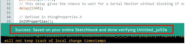
To compile the sketch, click ‘open full editor.’ Click the tick icon. This will verify and save the sketch inside the Arduino IoT cloud.

It will take a few moments to check for errors/problems with the sketch. You will receive a success message indicating that your sketch was saved.
Uploading Sketch to ESP32 board
After we have verified and saved our sketch now is the time to upload it to our ESP board. First, click ‘GO TO IOT CLOUD.’

Open Sketch and you will see a message below indicating that you need to install Create Agent to upload the code. Click ‘Learn More.’

Click ‘download’ and install Arduino Create Agent.

Or you can go to this link and download Arduino Create Agent. After that follow the instructions given on that link to install Arduino create agent.
Uploading code to ESP32 from Arduino Browser
You can upload code to ESP32 directly from the Arduino IoT cloud online. But make sure to install Arduino create agent.
After installing the agent, click on the open full editor button.
After that, the following window will appear. Select the board and click on the upload button to upload code to ESP32 as follows:

Now go back to the Arduino IoT cloud dashboard which we created earlier. You will see that the values of the sensor will be updated after every 1 second and also you will be able to toggle the LED from the switch.

You may also like to read:
- ESP32/ESP8266 Thermostat Web Server – Control Output Based on Temperature Threshold
- ESP32 OTA (Over-The-Air) Updates using AsyncElegantOTA Library and Arduino IDE
- BME280 with ESP32 – Display Values on OLED ( Arduino IDE)
- ESP32/ESP8266: Publish Sensor Readings to Google Sheets via IFTTT
- Send Email Alert Based on Temperature Threshold with ESP32 Web Server
- ESP32 Send Sensor Readings to ThingSpeak using Arduino IDE (BME280)
sir, in my project the result was erorr with the detail (redefenition of ‘DHT dht’) in the void loop. how i can fix it?. please help
Regards,
is it possible to display more data (temperature, etc.) on a chart?
Thanks: István