In this ESP32 tutorial, we will show you how to integrate voice assistance to ESP RainMaker with ESP32 using Arduino IDE. In a previous introductory tutorial, we introduced you to ESP RainMaker which is an innovative and newly launched cloud based IoT platform which enables customers to quickly build their own AIoT solutions based on enterprise-grade cloud computing, with a single-click deployment. Previously, we created an ESP RainMaker project whereby we were able to monitor DHT sensor data and control an LED connected with the ESP32 output pin from our mobile over the cloud. We will take that project a step ahead and include voice assistance inside ESP RainMaker to control the ESP32 GPIO output.
Refer to the getting started ESP RainMaker guide below:
Recommended Components
The following components are used in this project or are helpful for building it with the ESP32.
| Component | How it’s used in this project | Buy on Amazon |
|---|---|---|
| ESP32 Development Board | The main microcontroller board that runs the code for this project. | Check Price |
| Micro USB Cable | Connects the ESP32 to your computer for programming and power. | Check Price |
| Breadboard | Lets you build the circuit without soldering. | Check Price |
| Jumper Wires | Connect the ESP32 to the other components on the breadboard. | Check Price |
As an Amazon Associate we earn from qualifying purchases. Prices and availability are accurate as of the date/time indicated and are subject to change.
ESP RainMaker Voice Assistant Integration with Arduino IDE
Voice assistance plays a vital role in IoT projects and is a common practice. ESP RainMaker allows both Alexa and Google Voice Assistant integrations. Using voice assistance increases the productivity of the ESP RainMaker projects whereby users can setup home automation projects using this facility to control IoT devices with voice commands. The ESP RainMaker uses similar formats for devices and their parameters which are also used by Alexa and Google Voice Assistant. Therefore, it is possible to use these voice assistants with ESP RainMaker for voice controls.
To start working with RainMaker with Arduino IDE, we will be required to set up some configurations in the IDE. So let us begin!
Install ESP32 2.0 board package in Arduino IDE
The ESP32 board Packages version 2.0 has support for ESP RainMaker. We need to add that for our ESP32 board.
Open your Arduino IDE, and head over to File > Preferences. Now paste the following link in the additional Boards Manager URLs and press Ok.
https://raw.githubusercontent.com/espressif/arduino-esp32/gh-pages/package_esp32_index.json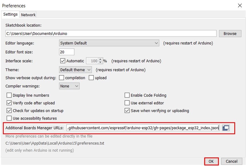
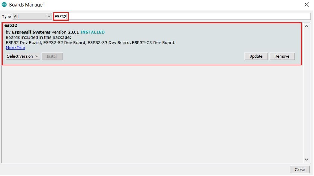
Head over to Tools > Board > Board Manager. Search for ‘ESP32’ and you can view that the version 2.0.1 is already installed.
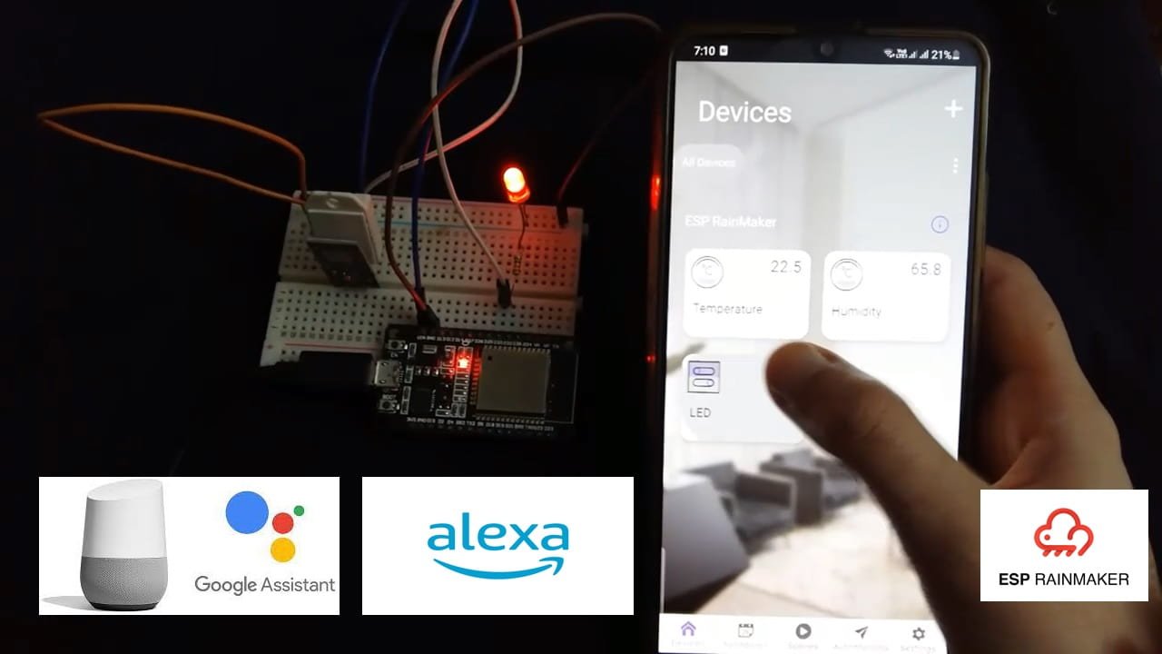
For demonstration purposes, we will interface our ESP32 board with a DHT22 sensor and an LED and monitor DHT sensor data and control an LED from our RainMaker mobile app. The app will consist of widgets showing the sensor readings that will update after every 5 seconds. There will also be a widget of a switch to toggle the LED ON/OFF. The LED will also be controlled through voice commands from Alexa or Google Voice Assistant.
DHT22 is a sensor which measures relative humidity and temperature. It provides a calibrated digital output with a 1-wire protocol. DHT sensors are pre-calibrated. We can directly connect them with ESP32 to obtain sensor output reading. They are internally composed of a humidity sensing sensor and a thermistor. These two components measure humidity and temperature.
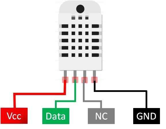
DHT22 Pinout
This following figure shows the pinout diagram of DHT sensors. DHT sensor consists of four pins. But on DHT modules only three pins are exposed to the pinout of the module and10k ohm pull-up resistor is internally connected to pin 2.
Pin Description
The following lists the pinout of the DHT sensor and their brief description. Pin number starts from left to right when you hold the sensor from the front end.
| DHT22 Pin | ESP32 |
|---|---|
| 1 (Vcc) | 3.3V |
| 2 (Data Out) | Any GPIO pin of ESP32 board along with a 10k ohm pull-up resistor |
| 3 (NC) | Not used |
| 4 (GND) | Ground |
- Vcc is the power supply pin. Apply voltage in a range of 3.3 V to 5.0 V to this pin
- Data Out is the digital output pin. It sends out the value of measured temperature and humidity in the form of serial data
- N/C is not connected
- GND: Connect the GND pin
Circuit Diagram of ESP32 with DHT22 sensor and LED
We will need the following components.
Required Components
- ESP32 board
- DHT22
- 10k ohm resistor (not required if using the DHT22 sensor module)
- 5mm LED
- 220 ohm current limiting resistor
- Bread Board
- Jumper wires
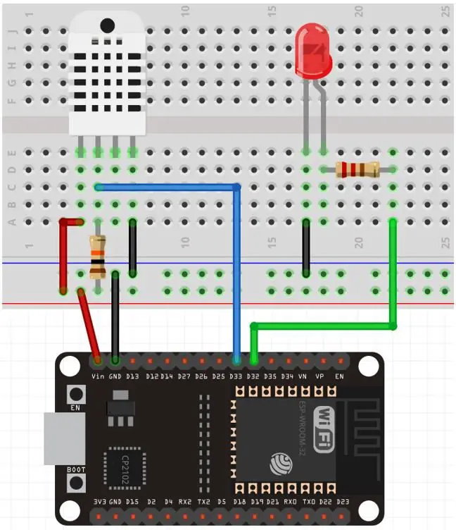
The first pin the DHT22 sensor is a power supply(VCC) pin. Connect it with the 3.3 volt pin of ESP32.
Data out is the pin through which we get temperature and humidity samples from the DHT sensor. Connect this pin with GPIO33 of ESP32 and also connect the data pin with a 10k pull-up resistor. But you can also use any digital pin of ESP32.
A Pull-up resistor is used to keep the data pin high for proper communication between the microcontroller and sensor. You can check the datasheet of DHT22 to get more information about it. DHT22 is also known by the name of AM2302.
- Third pin is not used
- Connect the fourth pin (GND) to the ground pin of the ESP32 board
The anode pin of the LED is connected with GPIO32 through a 220 ohm current limiting resistor. The cathode pin is grounded.
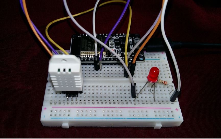
Connect ESP32 with DHT22 and an LED as shown in the schematic diagram below:
Install DHT11/DHT22 Library in Arduino IDE
Both DHT11 and DHT22 provide the output of temperature and humidity in the complex digital output format which can not be directly read with GPIO pins without writing any technique which can read these output signals. These sensors provide data through a single wire two-way communication protocol. A single process communication consists of 40 bits. But we do not need to worry about the working of these sensors and on which protocol we can receive this data. We have an Arduino library for DHT sensors which can be easily used to get values of temperature and humidity only by calling two lines of functions. We will see later on how to do it. Now let’s see how to install the DHT library in Arduino. This library is provided by Adafruit. Follow these steps to install the DHT sensor library:
Open Arduino IDE and click on Sketch > Library > Manage Libraries.
When you click on the manage libraries option, you will get this window. In this window write ‘DHT sensor‘ in the search bar and press enter.
You will see many options available for DHT11 and DHT22 libraries. Select Adafruit library and click on the install button. You can select the latest version from the version window.
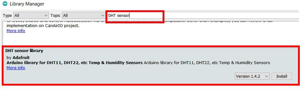
The same library can be used for both DHT11 and DHT22/AM2302 sensors.
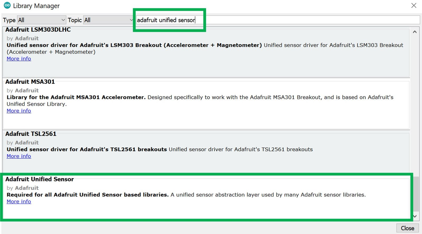
Adafruit also provides libraries for other sensors. So they provided a support package which is used to handle all sensor libraries. We also need to install the Adafruit Unified Sensor library. To install this, paste the Adafruit Unified Sensor search bar and select this option and click on the install button.
After installation of the libraries, restart your IDE.
You may also like to read:
- DHT11 DHT22 with ESP8266 NodeMCU – Display Readings on OLED
- DHT11 DHT22 with ESP32 – Display Readings on OLED
Install SimpleTimer Library
We will also install the SimpleTimer library by Alexander Kiryanenko. Open Arduino IDE and click on Sketch > Library > Manage Libraries.
When you click on the manage libraries option, you will get this window. In this window write ‘SimpleTimer‘ in the search bar and press enter.
Install the latest version of the library as highlighted below:

ESP RainMaker with Voice Assistant ESP32 Sketch
Open your Arduino IDE and go to File > New to open a new file. Copy the code given below and save it.
#include "RMaker.h"
#include "WiFi.h"
#include "WiFiProv.h"
#include "DHT.h"
#include <SimpleTimer.h>
#include <wifi_provisioning/manager.h>

#define DEFAULT_LED_MODE false
#define DEFAULT_Temperature 0
#define DEFAULT_Humidity 0

const char *service_name = "PROV_12345";
const char *pop = "1234567";

static uint8_t gpio_reset = 0;
static uint8_t DHTPIN = 33;
static uint8_t led_pin = 32;
bool led_pin_state = false;

bool wifi_connected = 0;

DHT dht(DHTPIN, DHT22);

SimpleTimer Timer;

static TemperatureSensor temperature("Temperature");
static TemperatureSensor humidity("Humidity");
static Switch my_switch("LED", &led_pin);

void sysProvEvent(arduino_event_t *sys_event)
{
  switch (sys_event->event_id) {
    case ARDUINO_EVENT_PROV_START:
#if CONFIG_IDF_TARGET_ESP32
      Serial.printf("\nProvisioning Started with name \"%s\" and PoP \"%s\" on BLE\n", service_name, pop);
      printQR(service_name, pop, "ble");
#else
      Serial.printf("\nProvisioning Started with name \"%s\" and PoP \"%s\" on SoftAP\n", service_name, pop);
      printQR(service_name, pop, "softap");
#endif
      break;
    case ARDUINO_EVENT_WIFI_STA_CONNECTED:
      Serial.printf("\nConnected to Wi-Fi!\n");
      wifi_connected = 1;
      delay(500);
      break;
    case ARDUINO_EVENT_PROV_CRED_RECV: {
        Serial.println("\nReceived Wi-Fi credentials");
        Serial.print("\tSSID : ");
        Serial.println((const char *) sys_event->event_info.prov_cred_recv.ssid);
        Serial.print("\tPassword : ");
        Serial.println((char const *) sys_event->event_info.prov_cred_recv.password);
        break;
      }
  }
}

void write_callback(Device *device, Param *param, const param_val_t val, void *priv_data, write_ctx_t *ctx)
{
  const char *device_name = device->getDeviceName();
  Serial.println(device_name);
  const char *param_name = param->getParamName();

  if (strcmp(device_name, "LED") == 0)
  {
    if (strcmp(param_name, "Power") == 0)
    {
      Serial.printf("Received value = %s for %s - %s\n", val.val.b ? "true" : "false", device_name, param_name);
      led_pin_state = val.val.b;
      (led_pin_state == false) ? digitalWrite(led_pin, LOW) : digitalWrite(led_pin, HIGH);
      param->updateAndReport(val);
    }
  }
}

void setup()
{
  Serial.begin(115200);

  pinMode(gpio_reset, INPUT);
  pinMode(led_pin, OUTPUT);
  digitalWrite(led_pin, DEFAULT_LED_MODE);

  dht.begin();

  Node my_node;
  my_node = RMaker.initNode("ESP RainMaker");

  my_switch.addCb(write_callback);
  my_node.addDevice(temperature);
  my_node.addDevice(humidity);
  my_node.addDevice(my_switch);

  //This is optional
  RMaker.enableOTA(OTA_USING_PARAMS);
  //If you want to enable scheduling, set time zone for your region using setTimeZone().
  //The list of available values are provided here https://rainmaker.espressif.com/docs/time-service.html
  // RMaker.setTimeZone("Asia/Shanghai");
  // Alternatively, enable the Timezone service and let the phone apps set the appropriate timezone
  RMaker.enableTZService();
  RMaker.enableSchedule();

  Serial.printf("\nStarting ESP-RainMaker\n");
  RMaker.start();

  Timer.setInterval(5000);

  WiFi.onEvent(sysProvEvent);

#if CONFIG_IDF_TARGET_ESP32
  WiFiProv.beginProvision(WIFI_PROV_SCHEME_BLE, WIFI_PROV_SCHEME_HANDLER_FREE_BTDM, WIFI_PROV_SECURITY_1, pop, service_name);
#else
  WiFiProv.beginProvision(WIFI_PROV_SCHEME_SOFTAP, WIFI_PROV_SCHEME_HANDLER_NONE, WIFI_PROV_SECURITY_1, pop, service_name);
#endif

}

void loop()
{
  if (Timer.isReady() && wifi_connected) {
    Serial.println("Sending DHT Sensor Data");
    float hum = dht.readHumidity();
    float temp = dht.readTemperature();

  Serial.print("Temperature: ");
  Serial.println(temp);
  Serial.print("Humidity: ");
  Serial.println(hum);

  temperature.updateAndReportParam("Temperature", temp);
  humidity.updateAndReportParam("Temperature", hum);
    Timer.reset();
  }

  // Read GPIO0 (external button to reset device
  if (digitalRead(gpio_reset) == LOW) { //Push button pressed
    Serial.printf("Reset Button Pressed!\n");
    // Key debounce handling
    delay(100);
    int startTime = millis();
    while (digitalRead(gpio_reset) == LOW) delay(50);
    int endTime = millis();

    if ((endTime - startTime) > 10000) {
      // If key pressed for more than 10secs, reset all
      Serial.printf("Reset to factory.\n");
      wifi_connected = 0;
      RMakerFactoryReset(2);
    } else if ((endTime - startTime) > 3000) {
      Serial.printf("Reset Wi-Fi.\n");
      wifi_connected = 0;
      // If key pressed for more than 3secs, but less than 10, reset Wi-Fi
      RMakerWiFiReset(2);
    } else {
          // Toggle device state
          led_pin_state = !led_pin_state;
          Serial.printf("Toggle State to %s.\n", led_pin_state ? "true" : "false");
          my_switch.updateAndReportParam(ESP_RMAKER_DEF_POWER_NAME, led_pin_state);
          (led_pin_state == false) ? digitalWrite(led_pin, LOW) : digitalWrite(led_pin, HIGH);
      }
  }
  delay(100);
}
How the Code Works?
We will start by including the necessary libraries for this project. As we are using the DHT22 sensor to monitor humidity and temperature readings, hence we include DHT.h. The <SimpleTimer.h> library will be used to add intervals between the sensor readings.
#include "RMaker.h"
#include "WiFi.h"
#include "WiFiProv.h"
#include "DHT.h"
#include <SimpleTimer.h>
#include <wifi_provisioning/manager.h>
As the ESP32 communicates with the mobile application using Bluetooth, hence we will specify the BLE credentials which are set as default.
const char *service_name = "PROV_12345";
const char *pop = "1234567";
Define ESP32 GPIO pins connected with the DHT sensor and the LED. Moreover declare another variable called ‘gpio_reset’ to hold GPIO0.
static uint8_t DHTPIN = 33;
static uint8_t led_pin = 32;

static uint8_t gpio_reset = 0;
Next create two bool variables, one for the LED pin state and another for Wi-Fi connection.
bool led_pin_state = false;
bool wifi_connected = 0;
Next we will create the object of DHT according to our defined pin number and DHT type. The first parameter is the ESP32 GPIO pin connected with the DHT sensor. The second parameter is the DHT type. In our case it is ‘DHT22.’ You can use this with DHT11, DHT21, and DHT22 sensors.
DHT dht(DHTPIN, DHT22);Declare Devices
Next we will declare devices. The framework provides some standard devices such as Switch, temperature sensor, Lightbulb etc. Refer to the official RainMaker website to get to know which standard devices you can use in your code.
Here we have declared two TemperatureSensor devices and one Switch device. The first device is for temperature and its widget name is called “Temperature.” The second device is for humidity and its widget name is called “Humidity.” The third device’s name is my_switch and its widget will be called “LED” as specified in the first parameter. The second parameter specifies the ESP32 GPIO pin connected with the LED.
static TemperatureSensor temperature("Temperature");
static TemperatureSensor humidity("Humidity");
static Switch my_switch("LED", &led_pin);
System Provisioning Event function
Next we have sysProvEvent(), which is the default function for system provisioning event. This function will obtain the Wi-Fi credentials and connect ESP32 to the router.
void sysProvEvent(arduino_event_t *sys_event)
{
  switch (sys_event->event_id) {
    case ARDUINO_EVENT_PROV_START:
#if CONFIG_IDF_TARGET_ESP32
      Serial.printf("\nProvisioning Started with name \"%s\" and PoP \"%s\" on BLE\n", service_name, pop);
      printQR(service_name, pop, "ble");
#else
      Serial.printf("\nProvisioning Started with name \"%s\" and PoP \"%s\" on SoftAP\n", service_name, pop);
      printQR(service_name, pop, "softap");
#endif
      break;
    case ARDUINO_EVENT_WIFI_STA_CONNECTED:
      Serial.printf("\nConnected to Wi-Fi!\n");
      wifi_connected = 1;
      delay(500);
      break;
    case ARDUINO_EVENT_PROV_CRED_RECV: {
        Serial.println("\nReceived Wi-Fi credentials");
        Serial.print("\tSSID : ");
        Serial.println((const char *) sys_event->event_info.prov_cred_recv.ssid);
        Serial.print("\tPassword : ");
        Serial.println((char const *) sys_event->event_info.prov_cred_recv.password);
        break;
      }
  }
}
write_callback()
The following callback function will be responsible for checking the particular device which sent the data and then change the parameter of the device accordingly. This callback function will be used for the device LED. If the device is ‘LED’ and its parameter is ‘Power’ then this function will check whether the state of the LED pin is HIGH or LOW. If the power is HIGH, the LED will turn ON. Similarly if the power if LOW, the LED will turn OFF.
You can refer to the official RainMaker website to get to know which parameters are available for the standard device types. As we are using the device Switch, hence it consists of two parameters: Name and Power.
void write_callback(Device *device, Param *param, const param_val_t val, void *priv_data, write_ctx_t *ctx)
{
  const char *device_name = device->getDeviceName();
  Serial.println(device_name);
  const char *param_name = param->getParamName();

  if (strcmp(device_name, "LED") == 0)
  {
    if (strcmp(param_name, "Power") == 0)
    {
      Serial.printf("Received value = %s for %s - %s\n", val.val.b ? "true" : "false", device_name, param_name);
      led_pin_state = val.val.b;
      (led_pin_state == false) ? digitalWrite(led_pin, LOW) : digitalWrite(led_pin, HIGH);
      param->updateAndReport(val);
    }
  }
}
setup()
Inside the setup() function we open the serial communication at a baud rate of 115200. Then we configure the reset pin as an input pin and the LED pin as an output pin. This is done by using pinMode() function and specifying the GPIO pin as the first parameter and the mode as the second parameter. Moreover, we will initially set the LED pin in a LOW state which is held in the variable ‘DEFAULT_LED_MODE’.
   Serial.begin(115200);

  pinMode(gpio_reset, INPUT);
  pinMode(led_pin, OUTPUT);
  digitalWrite(led_pin, DEFAULT_LED_MODE);
The dht.begin() function will initialize the DHT22 sensor and we can read temperature and humidity values from DHT11/DHT22 sensor.
dht.begin();Next, inside the setup() function we will declare a node with the name “ESP RainMaker.”
  Node my_node;
  my_node = RMaker.initNode("ESP RainMaker");
Then we add devices to our node. In our case, we are adding three devices with names temperature, humidity and my_switch respectively.
  my_node.addDevice(temperature);
  my_node.addDevice(humidity);
  my_node.addDevice(my_switch);
We will also declare the callback function for the switch device. This function aims to receive the data from the mobile app.
button.addCb(write_callback);Then we start the RainMaker application.
RMaker.start();Set an interval of 5 seconds between sensor readings and begin the Wi-Fi provisioning.
  Timer.setInterval(5000);

  WiFi.onEvent(sysProvEvent);

#if CONFIG_IDF_TARGET_ESP32
  WiFiProv.beginProvision(WIFI_PROV_SCHEME_BLE, WIFI_PROV_SCHEME_HANDLER_FREE_BTDM, WIFI_PROV_SECURITY_1, pop, service_name);
#else
  WiFiProv.beginProvision(WIFI_PROV_SCHEME_SOFTAP, WIFI_PROV_SCHEME_HANDLER_NONE, WIFI_PROV_SECURITY_1, pop, service_name);
#endif
loop()
Inside the loop() function, we send the DHT22 sensor data to ESP RainMaker and then reset it.
Firstly, we will send the sensor data when ESP32 is connected with the network and after 5 seconds have elapsed. Using readHumidity() method on the dht object and readTemperature() on the dht object we will get the value of humidity and temperature in Celsius from the DHT sensor. These readings will be saved in hum and temp variables respectively. The sensor data will be printed on the serial monitor. Next using temperature.updateAndReportParam() and humidity.updateAndReportParam() we will send the data. Inside the temperature device, we will update the Temperature parameter to the value saved in ‘temp.’ Likewise, inside the humidity device, we will update the Temperature parameter to the value saved in ‘hum’.
  if (Timer.isReady() && wifi_connected) {
    Serial.println("Sending DHT Sensor Data");
    float hum = dht.readHumidity();
    float temp = dht.readTemperature();

  Serial.print("Temperature: ");
  Serial.println(temp);
  Serial.print("Humidity: ");
  Serial.println(hum);

  temperature.updateAndReportParam("Temperature", temp);
  humidity.updateAndReportParam("Temperature", hum);
    Timer.reset();
  }
Next, we will reset the RainMaker to wiping off the Wi-Fi credentials. This will be done by pressing the BOOT button present on ESP32 to reset it. To reset ESP32, we will read the state of GPIO0 (gpio_reset) and reset ESP RainMaker accordingly.
 // Read GPIO0 (external button to reset device
  if (digitalRead(gpio_reset) == LOW) { //Push button pressed
    Serial.printf("Reset Button Pressed!\n");
    // Key debounce handling
    delay(100);
    int startTime = millis();
    while (digitalRead(gpio_reset) == LOW) delay(50);
    int endTime = millis();

    if ((endTime - startTime) > 10000) {
      // If key pressed for more than 10secs, reset all
      Serial.printf("Reset to factory.\n");
      wifi_connected = 0;
      RMakerFactoryReset(2);
    } else if ((endTime - startTime) > 3000) {
      Serial.printf("Reset Wi-Fi.\n");
      wifi_connected = 0;
      // If key pressed for more than 3secs, but less than 10, reset Wi-Fi
      RMakerWiFiReset(2);
    } else {
          // Toggle device state
          led_pin_state = !led_pin_state;
          Serial.printf("Toggle State to %s.\n", led_pin_state ? "true" : "false");
          my_switch.updateAndReportParam(ESP_RMAKER_DEF_POWER_NAME, led_pin_state);
          (led_pin_state == false) ? digitalWrite(led_pin, LOW) : digitalWrite(led_pin, HIGH);
      }
  }
  delay(100);
Demonstration
Choose the correct board and COM port before uploading your code to the board. Therefore go to Tools > Board and select ESP32 Dev Module.
If you are using ESP32, select the ESP32 Dev module as follows:

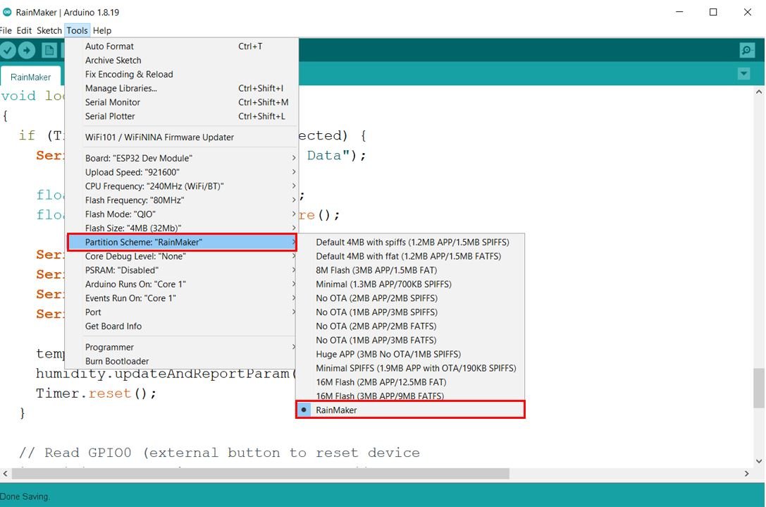
Next go to Tools > Partition Scheme and select RainMaker.
Then, go to Tools > Port and select the appropriate port through which your board is connected.
Click on the upload button to upload the code to ESP32 development board. After the code is successfully uploaded, open the serial monitor and set the baud rate to 115200.
Now press the ENABLE button of ESP32.

ESP RainMaker Mobile Application
The ESP RainMaker will start. You will receive the QR code and also the link to access it clearly.

Copy the HTTP address in a new web browser and press enter. You will be able to view the QR code clearly now.
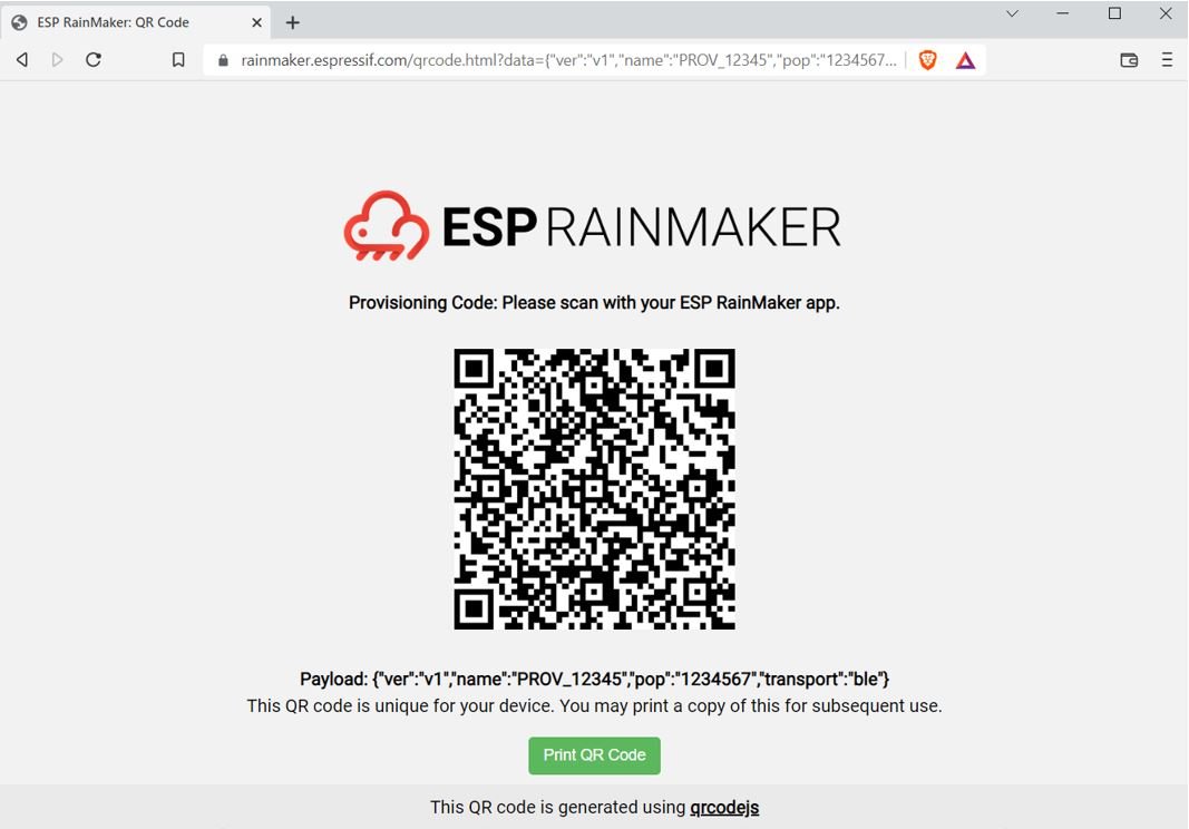
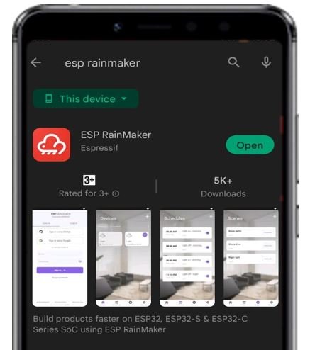
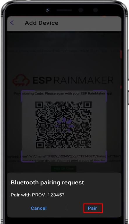
This is the QR code that we will scan with our ESP RainMaker app to configure it. Install RainMaker app in your smartphone from Play Store or App Store. It is available for both Android and iOS.
After you open the ESP RainMaker app, you will be required to Sign in. You can choose to create a new RainMaker account by signing up or sign in using GitHub or Google.

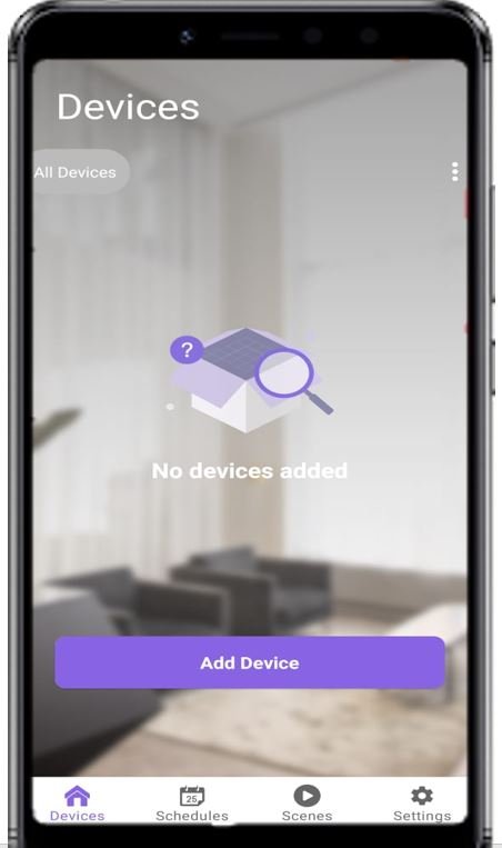
After you have successfully signed in, the Devices page will open. Here click Add Device button.
Turn the Bluetooth of your smartphone on. Scan the QR code that we accessed before using the app and pair by clicking on the pair button when the Bluetooth pairing request pops up.
Now the Claiming process starts.

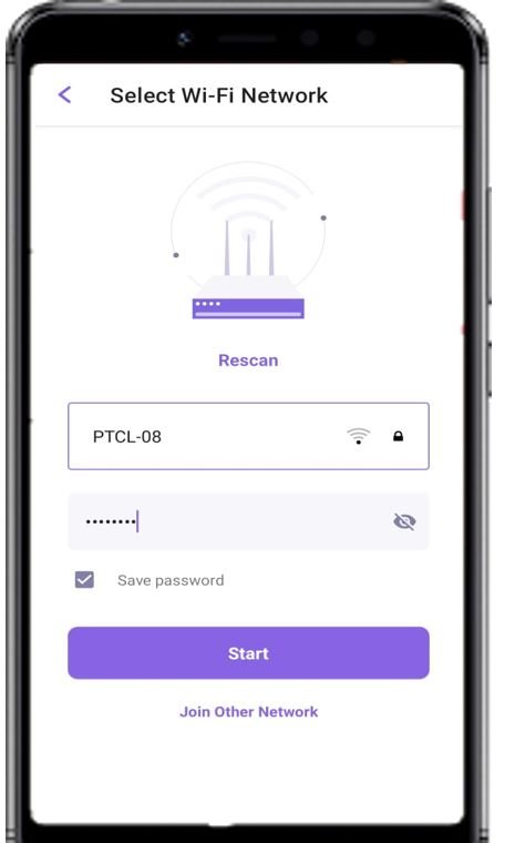
Now select the Wi-Fi network to connect to. Here the app has scanned some nearby networks for us. We can join other network as well.

Specify the SSID and password of the Wi-Fi network and click the Start button.
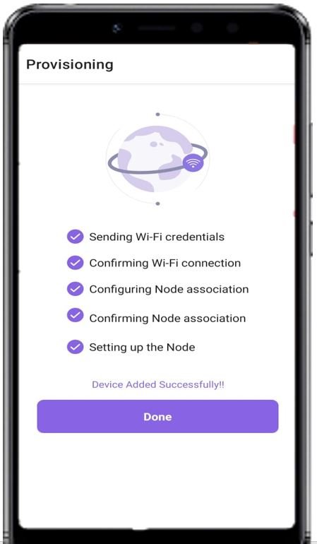
Now the Provisioning process starts. It consists of a number of steps which are verified before the device is successfully added. Click done after all steps are ticked.
If for some reason, any one one of the step fails, you can reset the ESP32 board to factory settings by long pressing the BOOT button for more than 10 seconds.
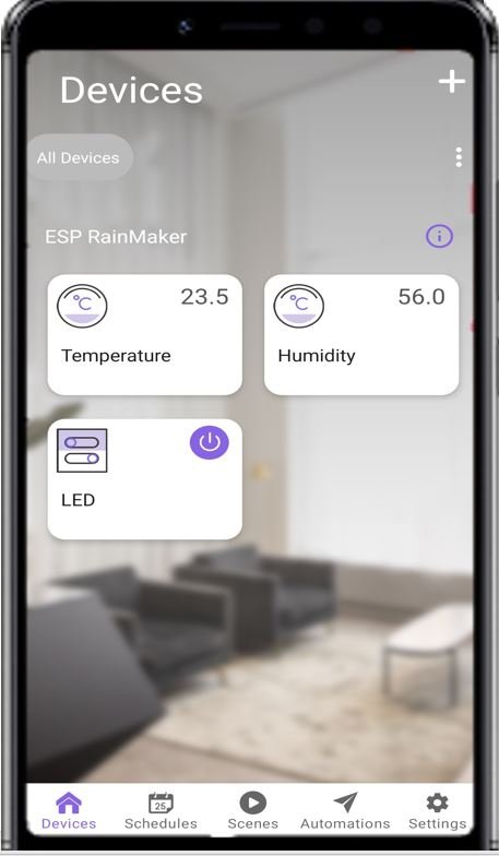
Now we can see that our widgets are created. We have three widgets, one for Temperature, another for Humidity and another for LED. The temperature and humidity readings will continuously update after every 5 seconds. These are also printed in the Arduino serial monitor.
Google Voice Assistant Integration
Now let us configure Google Voice Assistant inside our RainMaker project. Head over to Settings.’

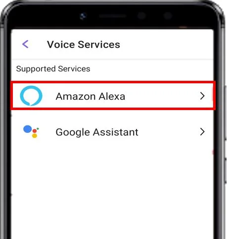
Then click ‘Voice Services.’

Here you can view that Amazon Alexa and Google Assistant are the supported voice services.

To use Google Assistant, we will have to first install the Google Home Application.

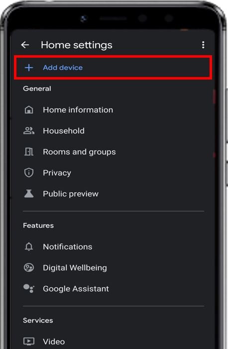
Open the app and go to Settings.

Click ‘Add device.’
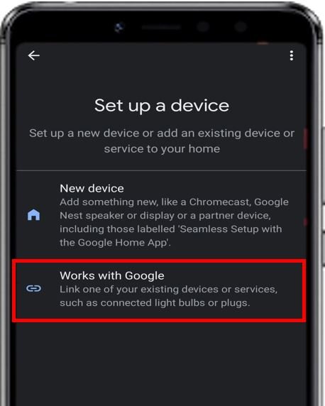
Now click ‘Works with Google.’
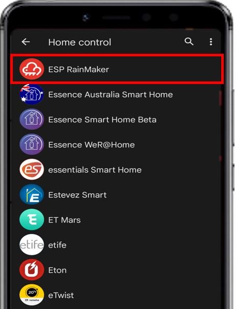
From the list of supported devices, choose ESP RainMaker.
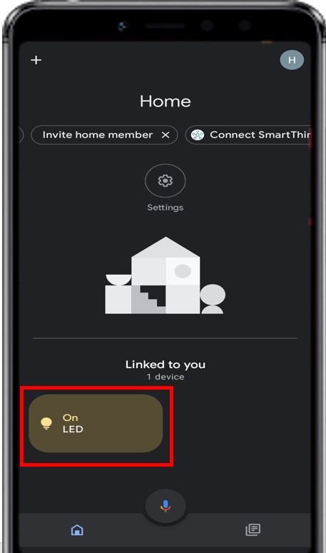
This opens the ESP RainMaker sign in page. Enter your ESP RainMaker email and password.

After you have successfully logged in, the Google Home App shows a shortcut to control the LED.
Amazon Alexa Integration
Similarly, to add Amazon Alexa voice service, open ESP RainMaker project and head over to Settings.’ Then click ‘Voice Services.’ Click Amazon Alexa.
Click ‘Link with Amazon Alexa.’

This opens the Amazon login page. Sign in to your Amazon account.

After successfully signing in, give permission for ESP RainMaker to access Alexa.

Video demo:
You may also like to read:
- ESP32 Motion Detection Notification on WhatsApp Number
- ESP32 MQTT Publish Multiple Sensor Readings to Node-Red with Arduino IDE
- ESP RainMaker Getting Started Tutorial with ESP32 and Arduino IDE
- Control ESP32 over Internet using Android App with MIT App Inventor
- ESP32-CAM Take and Send Photos via Email using an SMTP Server