In this tutorial, we will learn about ESP32 I2C communication protocol using different I2C devices having same and different addresses. We will discuss how to use multiple I2C devices with ESP32 having the same address by incorporating a hardware solution. By using a TCA9548A I2C Multiplexer, we will be able to increase the I2C addresses of the modules with the same I2C address and thereby connect these devices on the same I2C bus. Additionally, we will interface ESP32 with different sensors and devices that communicate via I2C protocol and program our board to run an I2C scanner. This scanner will determine the number of I2C devices connected with ESP32. So let us begin!
We have a same guide with Arduino:
For general introduction of I2C protocol, you can refer to this guide:
Recommended Components
The following components are used in this project or are helpful for building it with the ESP32.
| Component | How it’s used in this project | Buy on Amazon |
|---|---|---|
| ESP32 Development Board | The main controller acting as the I2C master that scans and communicates with all the connected devices. | Check Price |
| Micro USB Cable | Connects the ESP32 to your computer for uploading code and powering the board. | Check Price |
| Breadboard | Provides a solderless base to wire the ESP32, multiplexer and I2C devices together. | Check Price |
| Jumper Wires | Used to make the SDA, SCL, power and ground connections between the ESP32 and the I2C devices. | Check Price |
| 0.96″ SSD1306 OLED Display | Displays the sensor temperature readings and is used as a same-address I2C device behind the multiplexer. | Check Price |
| BME280 sensor | An I2C temperature sensor read by the ESP32 and shown on the OLED in this project. | Check Price |
| SHT31 sensor | A second I2C temperature sensor sharing the bus with the BME280 and OLED. | Check Price |
| Resistor Kit (220 Ω / 4.7k) | Provides the 10kΩ pull-up resistors needed on each multiplexer SDx/SCx channel. | Check Price |
As an Amazon Associate we earn from qualifying purchases. Prices and availability are accurate as of the date/time indicated and are subject to change.
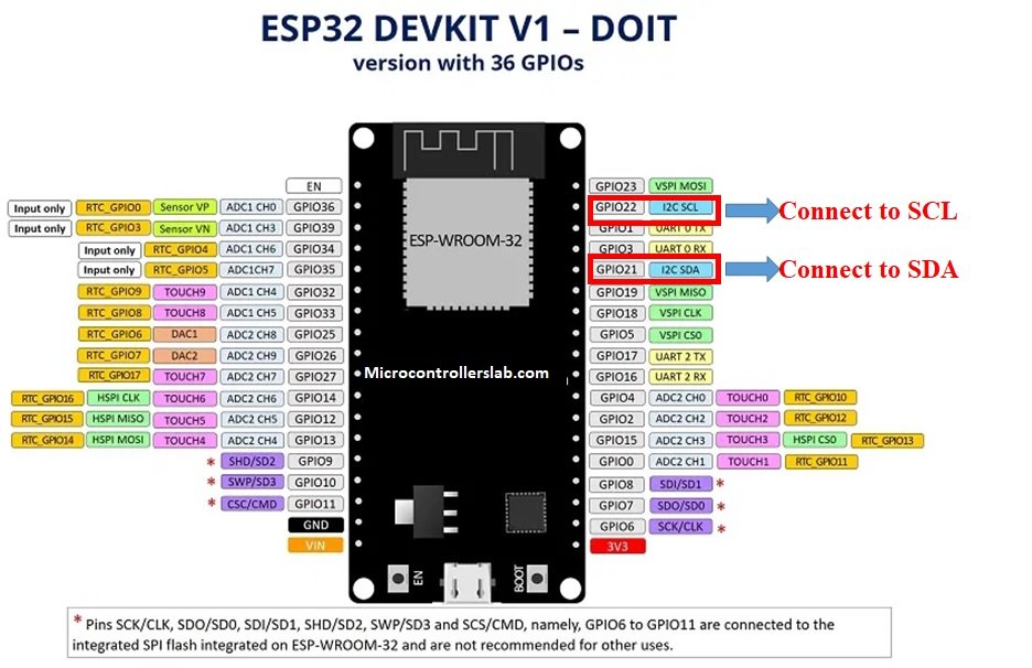
ESP32 I2C Pins
As mentioned earlier ESP32 has 2 I2C controllers which can be used to handle communication on an I2C bus. We can configure either as a master or slave. Now let’s see the default GPIO pins which are assigned to I2C controllers in the Arduino IDE library for ESP32.
The default I2C pin in ESP32 for SDA is GPIO21 and for SCL is GPIO22. If we want to change the GPIO pins we have to set them in code. The diagram below shows the pinout for the ESP32 which shows the default I2C pins.
The ESP32 I2C interface has the following features:
- Standard mode (100 Kbit/s)
- Fast mode (400 Kbit/s)
- Up to 5 MHz, yet constrained by SDA pull-up strength
- 7-bit/10-bit addressing mode
- Dual addressing mode
Now let’s see some examples. In the first section, we will see examples to connect different I2C devices which have different I2C addresses with ESP32. After that, we will see an example to connect the same I2C address devices with ESP32 using a TCA9548A 1-to-8 I2C multiplexer module.
Using Multiple Slave I2C Devices with ESP32 (I2C devices with different addresses)
In this section, we will first connect three different I2C devices (OLED, SHT32 (temperature sensor) and BME280 (temperature sensor)) with ESP32 using the default I2C pins. Then we will program our board to run an I2C scanner.
Components Required
- ESP32 development board
- SSD1306 OLED Display
- BME280 sensor
- SHT31 sensor
- Breadboard
- Connecting Wires
Interface ESP32 with OLED, BME280 and SHT31
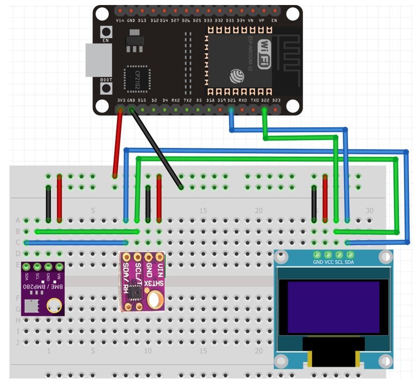
Let us see how to connect ESP32 with an OLED, BME280 module, and SHT31 module together. We will use a common I2C line to connect all the devices. ESP32 will act as a master, and the BME280 sensor, SHT31 sensor, and the OLED will act as slaves.
The connections between the four devices which we are using can be seen in the table below.
| ESP32 | SSD1306 OLED Display | BME280 | SHT31 |
| 3.3V | VCC | VCC | VCC |
| GPIO21 | SDA | SDA | SDA |
| GPIO22 | SCL | SCL | SCL |
| GND | GND | GND | GND |
We have used the same connections as specified in the table above.

ESP32 I2C Scanner Arduino Sketch
Every I2C device has an address associated with it. ESP32 uses this address to communicate with the slave via I2C protocol.
Now copy this code and upload it your board with all the I2C devices already connected with it.
This code will scan for any I2C devices connected with ESP32 and will specify the number of devices with the address in the serial terminal.
#include <Wire.h>

void setup() {
  Wire.begin();
  Serial.begin(115200);
  Serial.println("\nI2C Scanner");
    byte error, address;
  int nDevices;
  Serial.println("Scanning...");
  nDevices = 0;
  for(address = 1; address < 127; address++ ) {
    Wire.beginTransmission(address);
    error = Wire.endTransmission();
    if (error == 0) {
      Serial.print("I2C device found at address 0x");
      if (address<16) {
        Serial.print("0");
      }
      Serial.println(address,HEX);
      nDevices++;
    }
    else if (error==4) {
      Serial.print("Unknown error at address 0x");
      if (address<16) {
        Serial.print("0");
      }
      Serial.println(address,HEX);
    }
  }
  if (nDevices == 0) {
    Serial.println("No I2C devices found\n");
  }
  else {
    Serial.println("done\n");
  }
  delay(5000);
  Serial.print("i2c devices found:");
  Serial.println(nDevices);
}

void loop() {

}
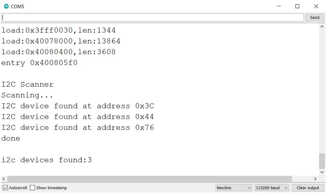
The I2C scanner identified 3 devices connected to the I2C interface. The I2C Address of OLED Display is 0x3C, SHT31 is 0x44 and BME280 is 0x76.
As all of these three I2C devices had different addresses therefore it was possible to share the same I2C bus.
ESP32 Display BME280 and SHT31 Temperature Readings on OLED
As seen in the I2C scanner, BME280, SHT31 and OLED have different I2C addresses, hence it is possible to share the same I2C bus. Let us show you a sketch which accesses temperature readings from these two sensors and displays them on the OLED.
We will use Arduino IDE to program our ESP32 development board. Thus, you should have the latest version of Arduino IDE.
Installing SSD1306 OLED Library in Arduino IDE
To use the OLED display in our project, we have to install the Adafruit SSD 1306 library in Arduino IDE. Follow the steps below to successfully install it.
Open Arduino IDE and click on Sketch > Library > Manage Libraries. The following window will open up.

Type ‘SSD1306’ in the search tab and install the Adafruit SSD1306 OLED library.

Installing BME280 Arduino Library
As we are connecting the BME280 sensor with ESP32, therefore, we will have to install BME280 libraries to our module. We will require two libraries for this project:
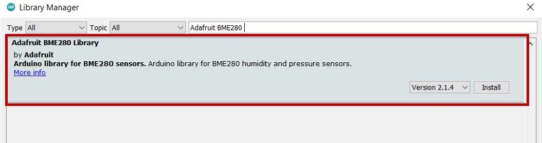
We will use the Library Manager in our Arduino IDE to install the latest versions of the libraries. Open your Arduino IDE and go to Sketch > Include Libraries > Manage Libraries. Type Adafruit BME280 library name in the search bar and install them both.
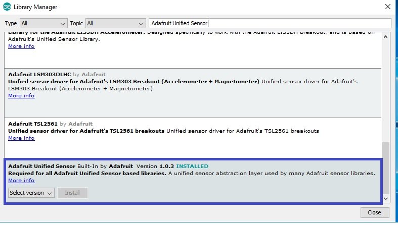
Open your Arduino IDE and go to Sketch > Include Libraries > Manage Libraries. Type Adafruit unified sensor library name in the search bar and install it.
Install SHT31 Arduino Library
As we are also connecting the SHT31 sensor module with ESP32, therefore, we will have to install the libraries to access the sensor data. We will require two libraries for this project:
- Adafruit SHT31
- Adafruit BusIO
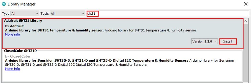
We will use the Library Manager in our Arduino IDE to install the latest versions of the libraries. Open your Arduino IDE and go to Sketch > Include Libraries > Manage Libraries. Type Adafruit SHT31 in the search bar and install the latest version.
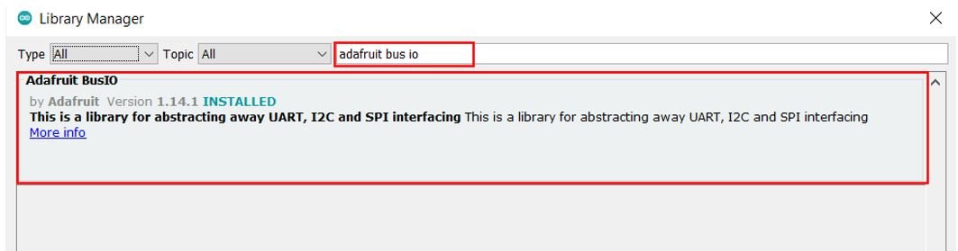
Type Adafruit BusIO in the search bar and install it as well.
ESP32 Display BME280 and SHT31 Temperature Readings on OLED Code
#include <Wire.h>
#include <Adafruit_Sensor.h>
#include <Adafruit_BME280.h>
#include <Adafruit_SHT31.h>
#include <Adafruit_GFX.h>
#include <Adafruit_SSD1306.h>

Adafruit_BME280 bme;
Adafruit_SHT31 sht31 = Adafruit_SHT31();

Adafruit_SSD1306 display = Adafruit_SSD1306(128, 32, &Wire);
unsigned long delayTime;

void setup() {
  Serial.begin(115200);
  display.begin(SSD1306_SWITCHCAPVCC, 0x3C);
   // init done
  display.display();
  delay(100);
  display.clearDisplay();
  display.display();
  display.setTextSize(1);
  display.setTextColor(WHITE);

  bool status;
  status = bme.begin(0x76);
  if (!status) {
    Serial.println("Could not find a valid BME280 sensor, check wiring!");
    while (1);
  }

  if (! sht31.begin(0x44)) {
    Serial.println("Check circuit. SHT31 not found!");
    while (1) delay(1);
  }

  Serial.println();
}


void loop() {

  display.setCursor(0,0);

  Serial.print("Temperature BME280 = "); Serial.print(bme.readTemperature()); Serial.println(" °C");
  display.print("Temperature: "); display.print(bme.readTemperature()); display.println(" C");

  display.setCursor(0,20);

  Serial.print("Temperature SHT31 = "); Serial.print(sht31.readTemperature()); Serial.println(" °C");
  display.print("Temperature: "); display.print(sht31.readTemperature()); display.println(" C");

  Serial.println();
  display.display();
  display.clearDisplay();

  delay(1000);
}
How the Code Works?
Now, let us understand how each part of the code works.
The code starts with including all the necessary libraries which are needed for the proper functionality of the code. The Wire.h will allow us to communicate through the I2C protocol. The rest of the libraries are the ones that we just installed for the functionality of the BME280 sensor, SHT31 sensor and OLED.
#include <Wire.h>
#include <Adafruit_Sensor.h>
#include <Adafruit_BME280.h>
#include <Adafruit_SHT31.h>
#include <Adafruit_GFX.h>
#include <Adafruit_SSD1306.h>
Then, we define the Adafruit_BME280 object named ‘bme’ by setting it on the default I2C GPIO pins and create the Adafruit_SHT31 object called ‘sht31.’
Adafruit_BME280 bme;
Adafruit_SHT31 sht31 = Adafruit_SHT31();
Now, we create another object named display which will be handling the OLED display. Also, define the size of the OLED display by passing arguments to the Adafruit_SSD1306() function.
Adafruit_SSD1306 display = Adafruit_SSD1306(128, 32, &Wire);setup()
Open the serial communication at a baud rate of 115200.
Serial.begin(115200);Initialize the OLED display by calling the begin() method on the display object.
display.begin(SSD1306_SWITCHCAPVCC, 0x3C); Next, we will clear the OLED screen by calling clearDisplay() function. Also, we set the color of the text using setTextColor() function and pass WHITE as an argument. If we have a dark background, we will display our text in white and if we have a bright background then we will display the text in black. Also, we set the font size using setTextSize().
  display.clearDisplay();
  display.display();
  display.setTextSize(1);
  display.setTextColor(WHITE);
Then, the BME280 sensor gets initialized using and in case of failure, an error message is printed on the serial monitor. Similarly, the SHT31 sensor is initialized as well. If the sensor initialization is not a success, a relevant message will be printed on the serial monitor.
  bool status;
  status = bme.begin(0x76);
  if (!status) {
    Serial.println("Could not find a valid BME280 sensor, check wiring!");
    while (1);
  }

  if (! sht31.begin(0x44)) {
    Serial.println("Check circuit. SHT31 not found!");
    while (1) delay(1);
  }
loop()
Inside the loop() function, we acquire the BME280 and SHT31 temperature readings using bme.readTemperature() and sht31.readTemperature respectively. These are then displayed in the Arduino serial monitor and the OLED after every second.
void loop() {

  display.setCursor(0,0);

  Serial.print("Temperature BME280 = "); Serial.print(bme.readTemperature()); Serial.println(" °C");
  display.print("Temperature: "); display.print(bme.readTemperature()); display.println(" C");

  display.setCursor(0,20);

  Serial.print("Temperature SHT31 = "); Serial.print(sht31.readTemperature()); Serial.println(" °C");
  display.print("Temperature: "); display.print(sht31.readTemperature()); display.println(" C");

  Serial.println();
  display.display();
  display.clearDisplay();

  delay(1000);
}
Demonstration
To see the demonstration of the above code, upload the code to ESP32. But, before uploading code, make sure to select ESP32 Dev Module from Tools > Board and also select the correct COM port to which the board is connected from Tools > Port.
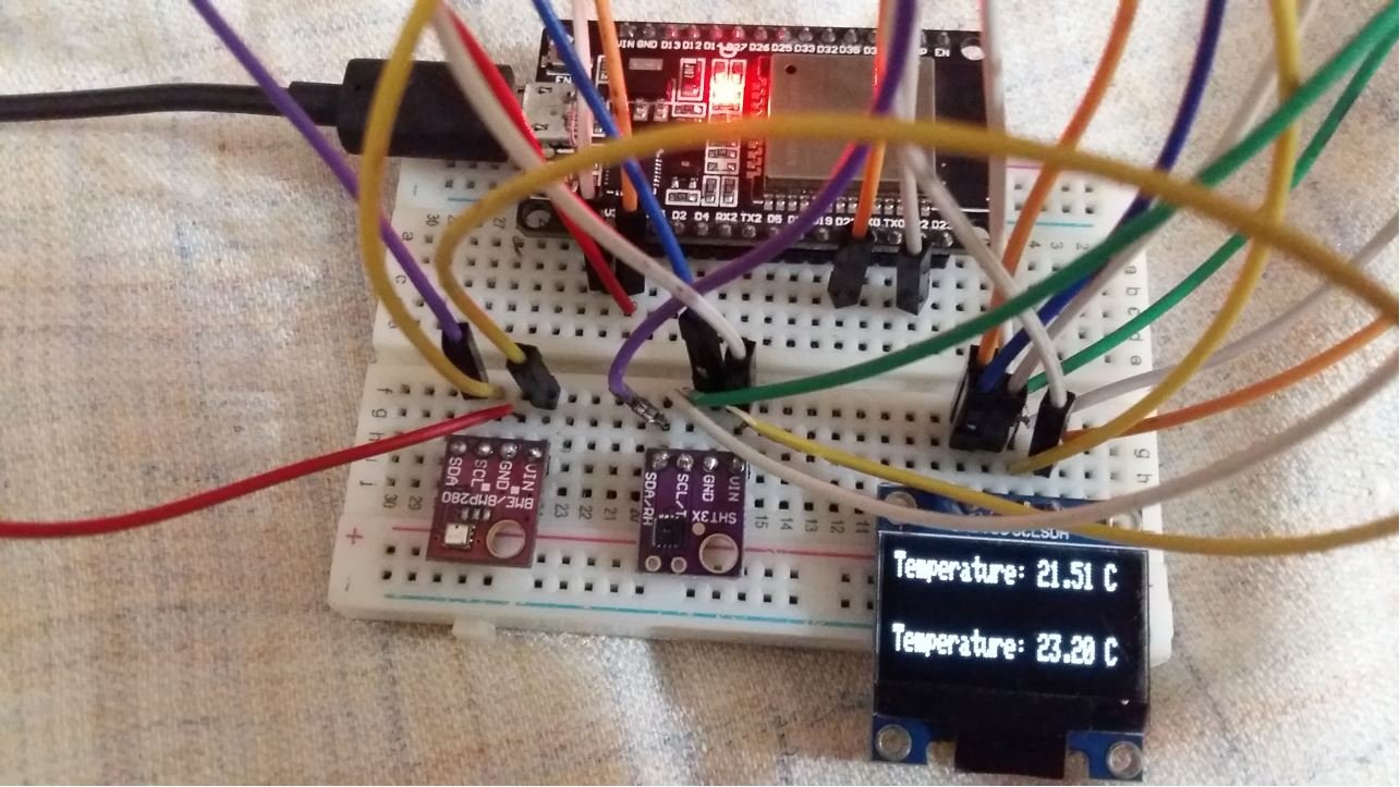
Once the code is successfully uploaded to the board, the OLED will start displaying the temperature readings from the two sensors as shown below:

Moreover, you can also view the temperature readings in the Arduino serial terminal. Remember to set the baud rate at 115200.
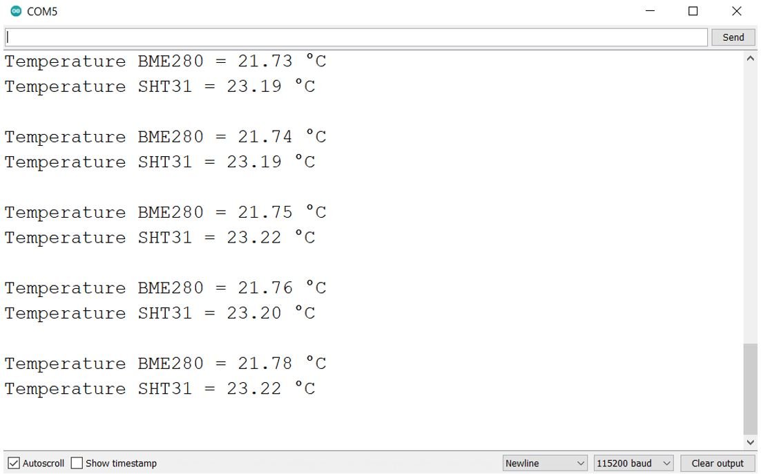
Use Same Addresses Multiple I2C Devices with ESP32 using TCA9548A Multiplexer IC
In the previous section, we were able to connect three different I2C devices on the same I2C pins of ESp32. This was because the ESP32 was able to identify them due to their unique address. However, what happens when we want to connect multiple devices with Arduino for I2C communication but they have the same address? For example, two BME280 sensors connected with ESP32 or two OLEDs connected with ESP32.
To use the same I2C devices with ESP32, we would either have to change the I2C address of the device or use an I2C multiplexer. However, it is not that simple to change the address of a device and it only allows limited devices to be used on the same I2C bus. Hence we can use a multiplexer eg. TCA9548A that will allow a maximum of eight devices with the same addresses to be connected to the same I2C bus. It operates on a range of 3-5.5 volts therefore making it convenient to use with microcontrollers having 3.3/5V logic pins.
The diagram below shows the TCA9548A multiplexer that we will use with I2C devices having the same address in order to communicate with ESP32.
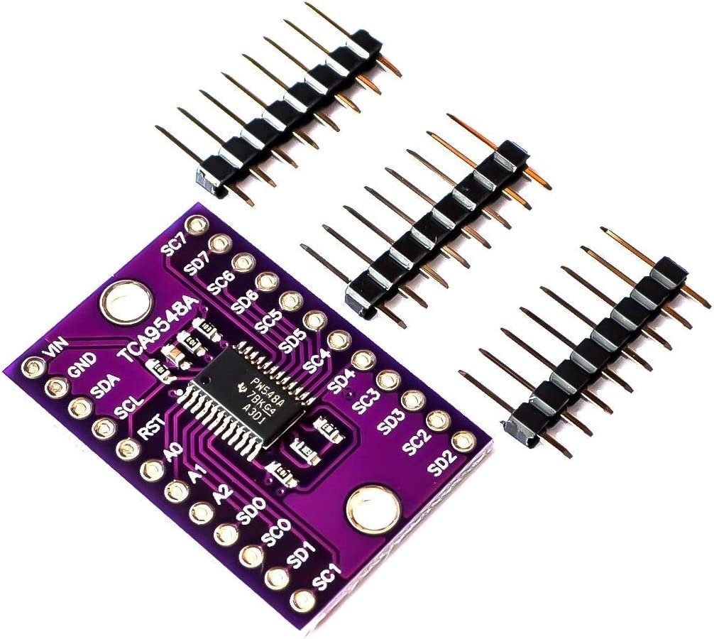
It is an electronic switching device that enables the users to connect multiple I2C busses with itself. All the slaves which have the same address need to be on connected to different busses. In order to communicate with the slave, the bus that is connected to the slave is switched by the user and then addressed.
TCA9548A Multiplexer Pinout
The diagram below shows the pinout of the TCA9548A multiplexer which acts as an I2C expander.
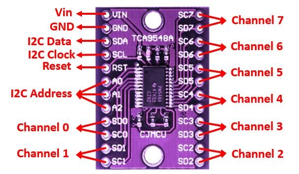
- Vin: This is the pin that provides power to the module. Connect 3.3V or Vin pin of ESP32 with this pin.
- GND: This is the pin which provides the common ground.
- SDA: This is the I2C serial data pin which is connected with the master device.
- SCL: This is the I2C serial clock pin which is connected with the master device.
- RST: This pin is responsible for resetting the multiplexer.
- A0, A1, A2: These three pins are used to change the I2C address of the multiplexer. By default, its address is 0x70 when these pins are unconnected. With the help of this module, a single I2C address can be expanded to a maximum of eight I2C addresses.
- SDx, SCx: These are the external I2C channels Channel 0 to Channel 7. Connect SDA pin with SDx and SCL pin with SCx for each I2C device having same address.
ESP32 Display Text on OLEDs using TCA9548A Multiplexer
Lets show you how to connect and program two OLEDs having the same address 0x3C with ESP32 using the TCA9548A multiplexer. We will require the following components:
Components Required
- ESP32 board
- Two SSD1306 OLEDs
- TCA9548A Multiplexer
- Four 10k ohm pullup resistors
- Breadboard
- Connecting Wires
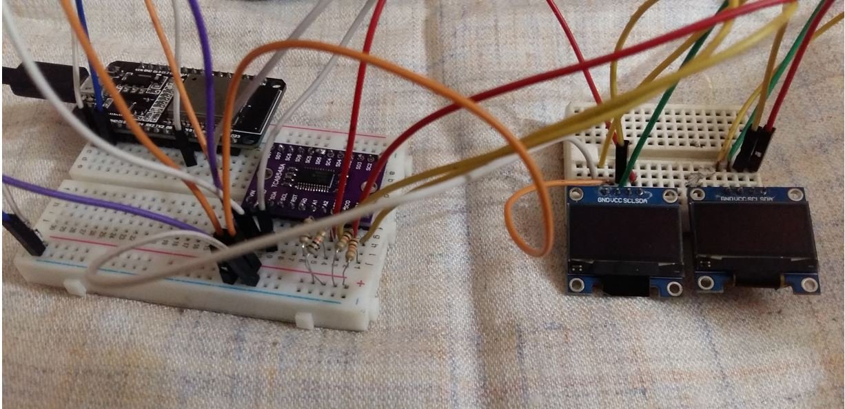
Interface ESP32 with TCA9548A multiplexer with OLEDs
Lets show you how to connect TCA9548A multiplexer with ESP32 and the OLEDs. The ESP32 will act as a master, and the OLEDs will act as slaves.
Follow the schematic diagram below to connect all the devices.
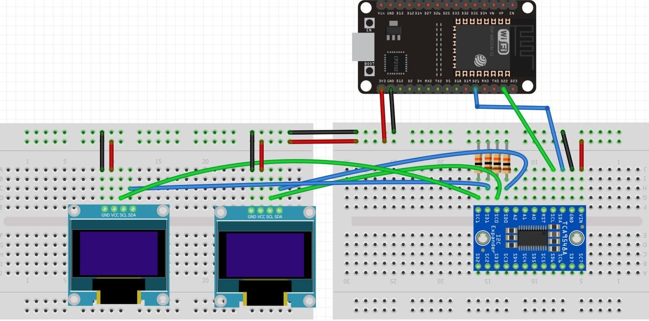
The table below shows the pins of TCA9548A connected with ESP32 and the two OLEDs.
| TCA9548A | Connections with rest of the devices |
| Vin | 3.3V of ESP32, VCC of both OLEDs |
| GND | GND of ESP32, GND of both OLEDs |
| SDA | GPIO21 of ESP32 |
| SCL | GPIO22 of ESP32 |
| SD0 | SDA of OLED1 with 10k ohm pullup resistor |
| SC0 | SCL of OLED1 with 10k ohm pullup resistor |
| SD1 | SDA of OLED2 with 10k ohm pullup resistor |
| SC1 | SCL of OLED2 with 10k ohm pullup resistor |
ESP32 Display Text on OLEDs using TCA9548A Multiplexer Code
#include <Wire.h>
#include <Adafruit_GFX.h>
#include <Adafruit_SSD1306.h>

Adafruit_SSD1306 display = Adafruit_SSD1306(128, 32, &Wire, -1);

void TCA9548A(uint8_t bus) //activate particular channel
{
  Wire.beginTransmission(0x70);  // TCA9548A address is 0x70
  Wire.write(1 << bus);          // send byte to select bus
  Wire.endTransmission();
}

void setup()
{
  Serial.begin(115200);
  Wire.begin();
  delay(100);

  TCA9548A(0);
  display.begin(SSD1306_SWITCHCAPVCC, 0x3C);
  display.clearDisplay();
  display.setTextSize(2);
  display.setCursor(20, 10);
  display.setTextColor(WHITE);
  display.println("OLED #1");
  display.display();

  TCA9548A(1);
  display.begin(SSD1306_SWITCHCAPVCC, 0x3C);
  display.clearDisplay();
  display.setTextSize(2);
  display.setCursor(20, 10);
  display.setTextColor(WHITE);
  display.println("OLED #2");
  display.display();

}

void loop() {

}
How the Code Works?
Now, let us understand how each part of the code works.
The code starts with including all the necessary libraries which are needed for the proper functionality of the code. The Wire.h will allow us to communicate through the I2C protocol and Adafruit_GFX.h and Adafruit_SSD1306.h are the OLED libraries.
#include <Wire.h>
#include <Adafruit_GFX.h>
#include <Adafruit_SSD1306.h>
Now, we create an object named display which will be handling the OLED display. Also, define the size of the OLED display by passing arguments to the Adafruit_SSD1306() function.
Adafruit_SSD1306 display = Adafruit_SSD1306(128, 32, &Wire, -1);Next we define a function for TCA9548A() that takes in a single parameter which is the I2C bus channel. This function is called whenever we want to activate a particular I2C channel.
void TCA9548A(uint8_t bus)
{
  Wire.beginTransmission(0x70);  // TCA9548A address is 0x70
  Wire.write(1 << bus);          // send byte to select bus
  Wire.endTransmission();
}
setup()
Open the serial communication at a baud rate of 115200 and initiate the I2C communication.
  Serial.begin(115200);
  Wire.begin();
Next we activate I2C channel 0 by calling TCA9548A() function as pass 0 as a parameter inside it. Our first OLED is connected with I2C channel 0. After that we initialize the OLED display, clear the screen, set the color of the text, set the font size and the cursor position. Then we print the text ‘OLED #1’ on the display.
  TCA9548A(0);
  display.begin(SSD1306_SWITCHCAPVCC, 0x3C);
  display.clearDisplay();
  display.setTextSize(2);
  display.setCursor(20, 10);
  display.setTextColor(WHITE);
  display.println("OLED #1");
  display.display();
Next we activate I2C channel 1 by calling TCA9548A() function as pass 1 as a parameter inside it. Our second OLED is connected with I2C channel 1. After that we initialize the OLED display, clear the screen, set the color of the text, set the font size and the cursor position. Then we print the text ‘OLED #2’ on the display.
TCA9548A(1);
  display.begin(SSD1306_SWITCHCAPVCC, 0x3C);
  display.clearDisplay();
  display.setTextSize(2);
  display.setCursor(20, 10);
  display.setTextColor(WHITE);
  display.println("OLED #2");
  display.display();
Demonstration
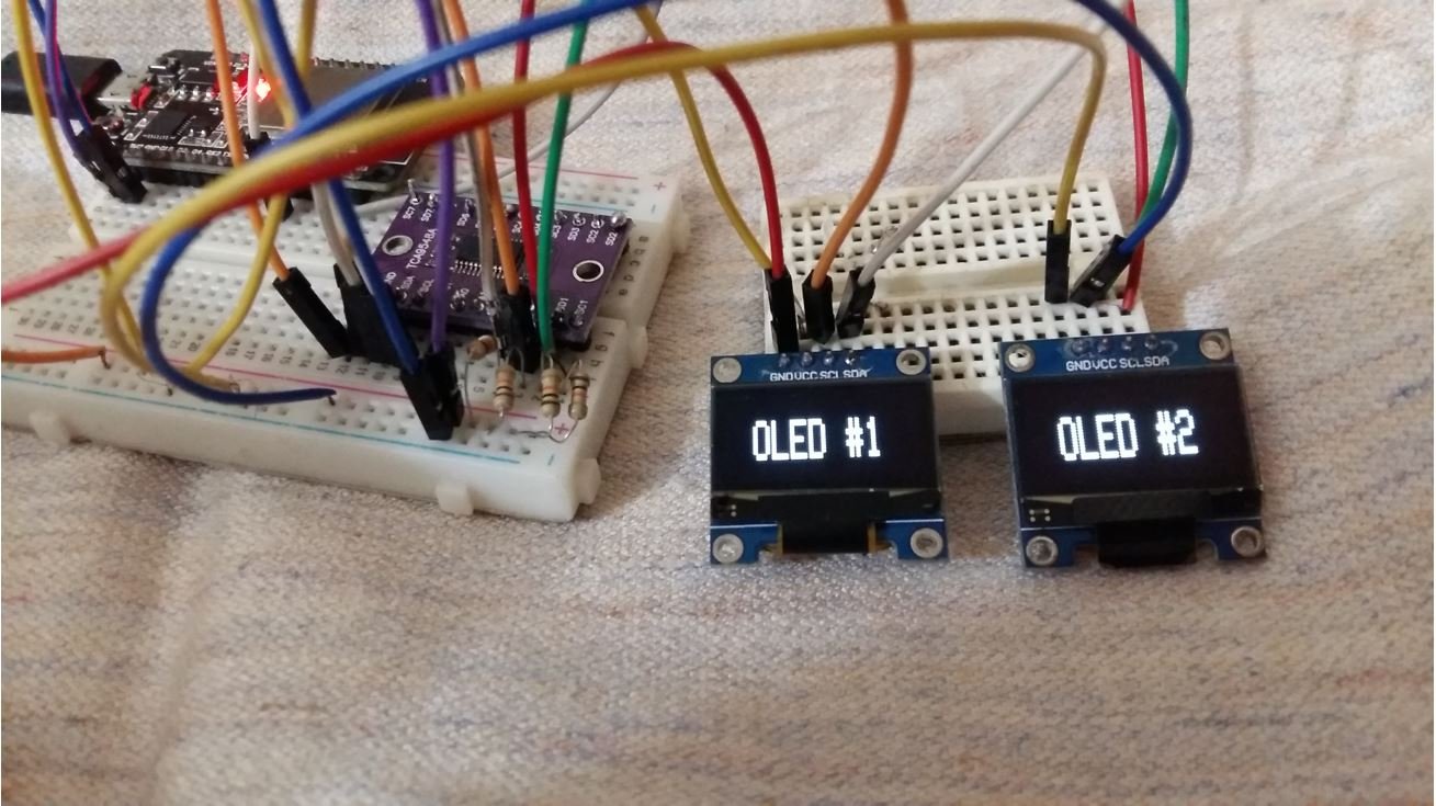
To see the demonstration of the above code, upload the code to ESP32. But, before uploading code, make sure to select ESP32 Dev Module from Tools > Board and also select the correct COM port to which the board is connected from Tools > Port.
Once the code is successfully uploaded to the board, the two OLEDs will start displaying their respective texts as shown below:
You may also like to read:
- I2C LCD with STM32 Blue Pill using STM32CubeIDE
- ESP32 I2C Communication Set Pins, Multiple Devices Interfaces and Change Pins
- I2C Communication Between Two Arduino Boards
- Raspberry Pi Pico I2C Communication
- I2C LCD with ESP32 and ESP8266 using MicroPython
- ADS1115 I2C external ADC with ESP32 in Arduino IDE