In this ESP32 tutorial, we will learn how to configure and use external interrupts with ESP32 GPIO pins in Arduino IDE. We will demonstrate this through an example with a push button and an LED. Additionally, we will also show you how to measure ESP32 interrupt latency via an oscilloscope measurement.
Recommended Components
The following components are used in this project or are helpful for building it with the ESP32.
| Component | How it’s used in this project | Buy on Amazon |
|---|---|---|
| ESP32 Development Board (DevKit V1) | The main controller that runs the project code and connects to the components. | Check Price |
| Micro USB Cable | Connects the ESP32 to your computer for programming and power. | Check Price |
| Breadboard | Lets you build the circuit and wire up parts without soldering. | Check Price |
| Jumper Wires | Make the connections between the ESP32 and the components on the breadboard. | Check Price |
| Tactile push button | Generates the external interrupt signal handled by the ESP32. | Check Price |
As an Amazon Associate we earn from qualifying purchases. Prices and availability are accurate as of the date/time indicated and are subject to change.
Prerequisites
We will use Arduino IDE to program our ESP32 development boards. Thus, you should have the latest version of Arduino IDE. Additionally, you also need to install the ESP32 plugin. If your IDE does not have the plugin installed you can visit the link below:
Interrupts
Interrupts are used to handle events that do not happen during the sequential execution of a program. For example, we want to perform certain tasks and these tasks execute sequentially in your Arduino program. But there are few tasks that only execute when a special event occurs such as an external trigger signal to the digital input pin of a microcontroller.
External Interrupts
An external interrupt or a ‘hardware interrupt’ is caused by the external hardware module. For example, there is a Touch Interrupt which happens when touch is detected and a GPIO interrupt when a key is pressed down. In this tutorial, we will focus on this type of interrupt.
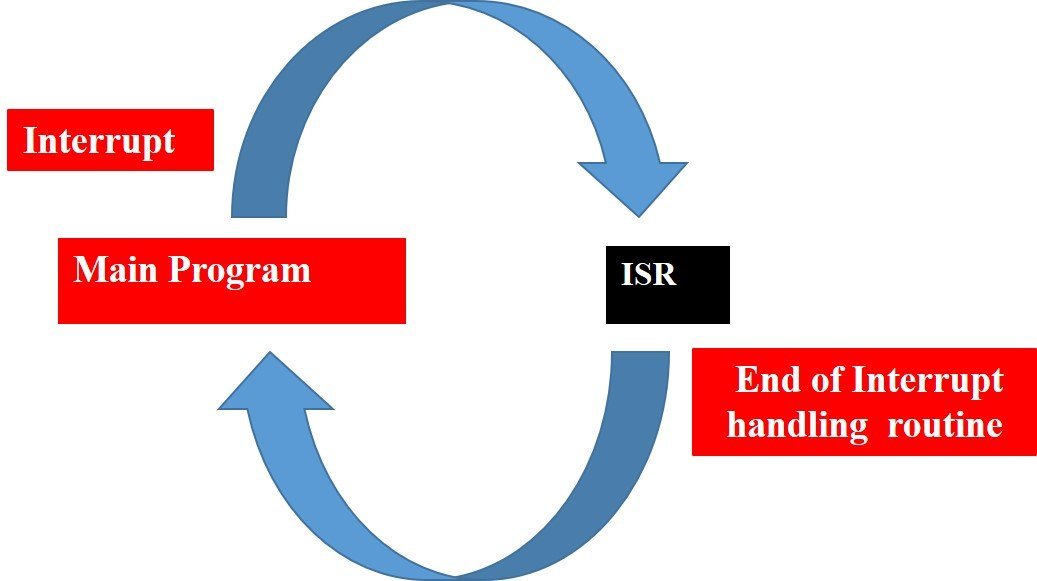
With interrupt, we do not need to continuously check the state of the digital input pin. When an interrupt occurs (a change is detected), the processor stops the execution of the main program and a function is called upon known as ISR or the Interrupt Service Routine. The processor then temporarily works on a different task (ISR) and then gets back to the main program after the handling routine has ended. This is shown in the figure below.
An example can be that of pressing a push button or motion detection with a PIR Sensor. In both cases, a push button or a PIR motion sensor can be used to trigger an interrupt. Therefore, when an external event occurs, the processor stops what it is doing and executes the interrupt service routine which we define for the respective event. After that, it returns to the current program. External Interrupts are extremely useful because with their help we do not have to constantly monitor the digital input pin state.
In a previous tutorial, we used the example of PIR sensor to demonstrate external interrupts with ESP32 in Arduino IDE as well in Micro Python. Follow the links below to access the guides:
- MicroPython: Interrupts with ESP32 and ESP8266 – PIR Sensor Interfacing Example
- ESP32 Interrupts and Timers with PIR Sensor using Arduino IDE
This time however we will use a push button to handle the external interrupt.
ESP32 Interrupt Pins
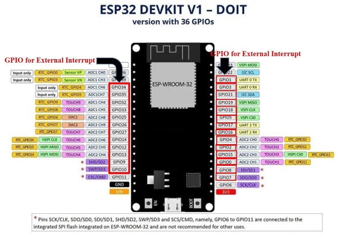
For ESP32 we can use all GPIO pins for external interrupt except for GPIO6, GPIO7, GPIO8, GPIO9, GPIO10, and GPIO11. The diagram below shows the pinout of the GPIO pins in ESP32 that can be used.
Configuring Interrupts in Arduino IDE
Now let us look at how to set up external interrupts in our ESP32 development boards using Arduino IDE. The following steps need to be followed.
We will use the following function to configure an interrupt in Arduino IDE:
attachInterrupt(digitalPinToInterrupt(pin), ISR, mode)The attachInterrupt() function takes in three arguments:
- digitalPinToInterrupt(pin): This is a function which takes in the GPIO pin of the ESP32 board as a parameter inside it. The pin denotes the GPIO associated with the pin which will cause an interrupt to occur. For example if setting GPIO2 as an interrupt pin the function will be specified as digitalPinToInterrupt(2). You can use any of the ESP32 interrupt pins shown in the diagram above, as a parameter inside this function.
- ISR: This is the second argument used to set up an interrupt. It is a special kind of function known as the Interrupt Service Routine which takes in no parameters and also returns nothing. Whenever the interrupt will occur this function will be called.
- mode: This denotes the triggering action for the interrupt to occur. The following four parameters are used to specify the mode:
LOW: This is used to trigger the interrupt when the pin is in a low state.
CHANGE: This is used to trigger the interrupt when the pin changes its state (HIGH-LOW or LOW-HIGH)
RISING: This is used to trigger the interrupt when the pin goes from LOW to HIGH.
FALLING: This is used to trigger the interrupt when the pin goes from HIGH to LOW.

External Interrupt using a Push Button to toggle LED
Now we will learn how to handle interrupts in the ESP32 board using a push button to toggle an LED. The push button will be connected to an interrupt pin of ESP32 and configured as an input. Whereas the LED will be set up as a digital output. The LED will be toggled on each rising edge.
The following components are required:
- ESP32 development board
- Push button
- One 5mm LED
- One 220 ohm resistor
- One 10k ohm resistor
- Breadboard
- Connecting Wires
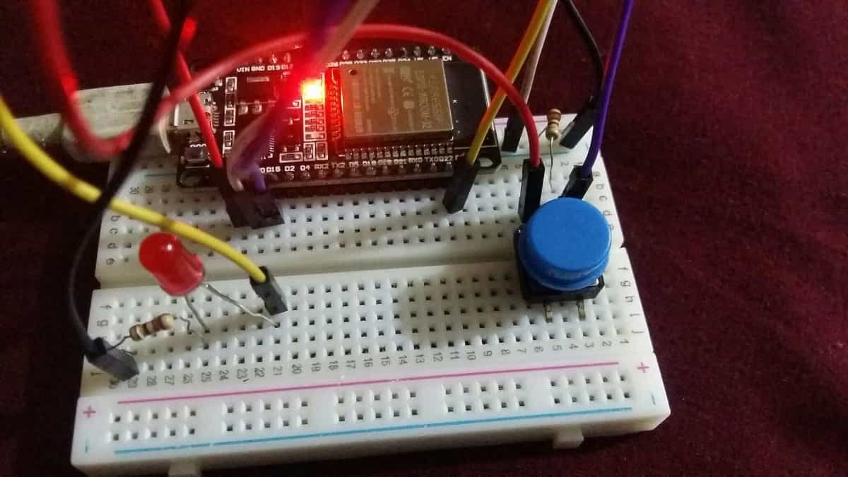
Assemble your circuit as shown below:
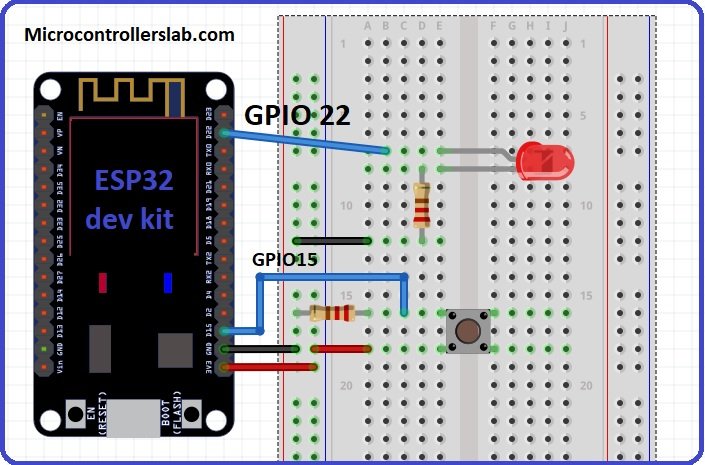
In the above schematics, we can see that GPIO22 is connected with the anode pin of LED, and the cathode pin is connected with the common ground through the 220-ohm resistor.
The push button has four terminals. One terminal is powered by 3.3 volts from ESP32 and the other terminal is connected by GPIO15 and the 10k ohm resistor which acts as a pull-down resistor. The other end of the resistor is connected with the common ground.
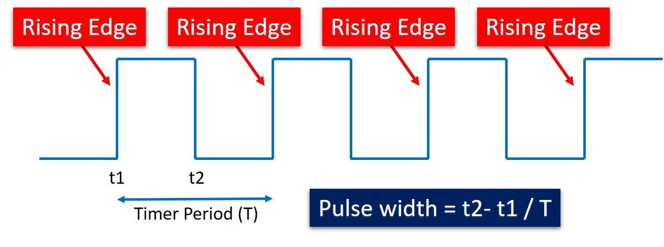
When the pushbutton is not pressed, logic low will appear on GPIO15, or push button state will be low and when the push button is pressed, a logic high will be on GPIO15. That means a rising edge occurs when a push button is pressed. We can detect this rising edge with the help of interrupt pins of ESP32. You can use any appropriate ESP32 interrupt GPIO pin which we showed you at the start.
Recommended reading: Push button with ESP32 – GPIO pins as digital input
How the Push Button works with External Interrupt?
The push button acts as a source for the external interrupt. That means we connect the output of the push button with the GPIO pin of ESP32. Furthermore, we attach the rising edge-triggered interrupt to this GPIO pin. That means this GPIO pin will trigger the interrupt whenever it will sense a rising edge on its input.
When the push button will be pressed, an external interrupt is caused, the LED will toggle. If initially it was OFF, it will turn ON and vice versa.
Arduino Sketch External Interrupt
Open your Arduino IDE and go to File > New to open a new file. Copy the code given below in that file and save it.
#define pushButton_pin   15
#define LED_pin   22

void IRAM_ATTR toggleLED()
{
  digitalWrite(LED_pin, !digitalRead(LED_pin));
}

void setup()
{
  pinMode(LED_pin, OUTPUT);
  pinMode(pushButton_pin, INPUT);
  attachInterrupt(pushButton_pin, toggleLED, RISING);
}

void loop()
{
}
How the Code Works?
First, we will define the GPIO pin through which the LED is connected. It is GPIO22 in our case. Also, we will define the GPIO pin through which the push button is connected. It is GPIO15 in our case.
#define pushButton_pin   15
#define LED_pin   22
Next, we will define the function which will act as the Interrupt Service Routine(ISR). It is called toggleLED(). Whenever the push button will be pressed, this function will be called. It will toggle the state of the LED. This will be achieved by using the digitalWrite() function and using the led_pin and !digitalRead(LED_pin) as parameters inside it. The digitalRead() function is used to read the state of the input pin. This digitalRead() function returns either logical HIGH or logical LOW input. If input state of the pin is HIGH, it will return HIGH and otherwise low.
void IRAM_ATTR toggleLED()
{
  digitalWrite(LED_pin, !digitalRead(LED_pin));
}
Inside the setup() function, we will first configure the LED pin as an output pin and the push button pin as an input pin. Then, we will set the interrupt by using the attachInterrupt() function and pass three arguments inside it. These include the ‘pushButton_pin’ that configures the interrupt with the pin connected with the push button, the ISR which is the ‘toggleLED’ function which we defined previously, and lastly RISING which is the mode for the interrupt set up. The pushButton_pin state will go through a change (LOW to HIGH) when the push button will be pressed and call the toggleLED function. This will in return change the state of the LED_pin.
void setup()
{
  pinMode(LED_pin, OUTPUT);
  pinMode(pushButton_pin, INPUT);
  attachInterrupt(pushButton_pin, toggleLED, RISING);
}
Demonstration
Choose the correct board and COM port before uploading your code to the ESP32 board. Go to Tools > Board and select ESP32 Dev Module.

Next, go to Tools > Port and select the appropriate port through which your board is connected.

Click on the upload button to upload the code into the ESP32 board. After you have uploaded your code to the board press its ENABLE button.

Now press the push button. The LED will turn ON. Press the push button again. The LED will turn OFF. Likewise, keep on pressing a push button and the LED will keep on toggling.
Watch the demonstration video below:
Sometimes the LED will toggle inconsistently as well. This is because of the push button bouncing which can be interpreted as a single button press as many. To counter that, we can include a debouncing circuit to our circuit design.
ESP32 Interrupt Latency
Interrupt Latency is the time when the interrupt was triggered to the time the event handler started execution. Ideally, we would want this time to be less. There are several factors that affect the interrupt latency including the microcontroller’s architecture/design, clock speed, type of interrupt controller used and the operating system itself.
We will show you to measure the time taken when the external interrupt was triggered till the start of the ISR routine.
What is ISR routine?
An interrupt service routine (ISR) is also called an interrupts handler. There are many different types of interrupt handlers which may handle many different types of interrupts. Like the clock in a system has its own interrupt handler same as the keyboard it also has its own interrupt handler. Every device which is existing has its interrupt handler.
Generally, ISR will use a volatile variable which can still be used between other pieces of code. Also, ISR should be as short and fast as possible. Interrupts execute immediately and stop everything that the program is currently doing in order to jump into the interrupts function and execute the code. Furthermore, the interrupts will return to the same point within the software where it had previously left off.
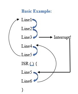
Above is an example of execution. So line by line the code will execute until the interrupt is called on Line3. Then the function jumps down to the ISR and starts executing line5 and line 6. After executing the lines within the ISR it jumps back to line4 and finishes the execution as routine. If it is in a loop then it goes back to line1.
ESP32 Interrupt Latency Measurement
Now let us measure the interrupt latency of the example which we provided above where we used a push button to trigger the interrupt and toggled the LED pin. We will basically measure the time the CPU took to handle the external interrupt by changing the state of the LED pin.
You may like to read:
- ESP8266 Interrupts and Timers Arduino IDE – PIR Motion Sensor Example
- Arduino Timer Interrupts – Explained with Timer1 and Timer2 Examples
- ESP32 Interrupts and Timers with PIR Sensor using Arduino IDE
- MicroPython: Interrupts with ESP32 and ESP8266 – PIR Sensor Interfacing Example
- Timer Interrupt TM4C123 – Generate Delay with GPTM Interrupt Service Routine
- GPIO Interrupts TM4C123 Tiva Launchpad – External Interrupts
- FreeRTOS Interrupt Management Examples with Arduino
Güzel bir çalışma çok yararlı oldu.
Gerçekten gerçekten muhteşem
The graphic on this page showing how to wire the circuit on a breadboard labelled: ‘Assemble your circuit as shown below:’ will work as shown, but the ground and power wires are reversed according to the color codes on the breadboard This could cause serious smoke if other components were added without noticing the error. The leftmost vertical row of pins next to the red line should be connected to the 3V3 pin and the second vertical row next to the blue line should be ground. The breadboards I have all show a ‘+’ on the red column and ‘-‘ on the blue. Other changes to the circuit must be made accordingly.