Interrupts are used to handle events that do not happen during the sequential execution of a program. There are two types of interrupts for the Arduino microcontroller. Hardware or external interrupt and Timer interrupt. In a previous tutorial, we looked at Arduino external interrupt where the interrupt was caused by is caused by the external hardware module. However, in this user guide, we will focus on Timer interrupts of Arduino, its introduction, and how to configure them in our Arduino. This guide is highly useful for people who want to increase the productivity of their program sketch by incorporating timer interrupts to enhance the capabilities of their microcontroller.
Recommended Components
The following components are used in this project or are helpful for building it with the Arduino.
| Component | How it’s used in this project | Buy on Amazon |
|---|---|---|
| Arduino Uno R3 | The main microcontroller board that runs the sketch and reads the sensors/modules in this project. | Check Price |
| Breadboard | Lets you wire the components to the Arduino without soldering for quick prototyping. | Check Price |
| Jumper Wires | Connect the Arduino pins to the module and other parts on the breadboard. | Check Price |
As an Amazon Associate we earn from qualifying purchases. Prices and availability are accurate as of the date/time indicated and are subject to change.
Interrupts
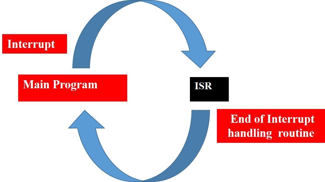
Interrupts are used to handle events that do not happen during the sequential execution of a program. For example, we want to perform certain tasks and these tasks execute sequentially in your Arduino program. But there are few tasks that only execute when a special event occurs such as an external trigger signal to the digital input pin of a microcontroller.
Interrupts are the section of hardware and software on a microcontroller which is capable of monitoring the external event on the input pin when any external event is monitored then the program stops sequential execution at this point and jumps into their ISR function which is an interrupt handler then after executing the ISR function, it goes back to the point where the external event is monitor than it completes sequential execution.
To learn how to generate external interrupts with Arduino follow the tutorial given below:
Arduino Timer Interrupts
Timer interrupts in Arduino pause the sequential execution of a program loop() function for a predefined number of seconds (timed intervals) to execute a different set of commands. After the set commands are executed, the program resumes again from the same position. The Arduino comes with three timers known as Timer0 (8-bit timer), Timer1 (16-bit timer), and Timer2 (8-bit timer). They act as a clock and are used to keep track of time based events. These timers will be programmed using registers which we will learn about.
Our user guide will focus on learning how to generate Timer1 and Timer2 interrupts of Arduino.
How do Timer Interrupts work?
As Timer1 and Timer2 are 16-bit and 8-bit timers respectively hence they can count from 0-65537 for Timer1 and 0-255 for Timer2. Depending on the timer mode which is selected the timer will start by increasing its value until it reaches its maximum count then go back to 0. This creates a triangle shaped curve which the timer follows. This will cause the interrupt to occur as the value increases from 0-255 in the case of Timer2 and then goes back to 0 and repeats again.

Each of the three timers are able to generate different interrupts.
Timer1 can generate Compare Match, Overflow and Input Capture interruptions. In compare match, the interrupt is triggered when the timer value in the register is equal to the compare value. If we set the compare value equal to 50 then whenever the Timer1 will reach this value an interrupt will be called. The next type of interrupt is overflow. This is triggered whenever the timer value reaches its maximum value. The last type of interrupt is input capture. Whenever an external trigger occurs, the value gets saved in a different register.
On the other hand Timer0 and Timer2 can generate Compare Match and Overflow interruptions only.
Timer Speed
One important aspect of the timer clock is its speed at which it increments the counter. It is directly related to the prescaler we will set for our timer. The prescaler can take values from 1, 8, 64, 256 or 1024 which is then used to divide the maximum Arduino clock speed i.e 16MHz to find the maximum timer speed.
Timer speed (Hz) = Arduino clock speed (16MHz) / prescaler
If the prescaler is set to 1 that means the timer will increase the counter at 16MHz on the other hand if the prescaler is set o 8 then the counter will increment at 2MHz. Thus, the prescaler will be able to control the speed of incrementation of the timer counter.
The following table shows the clock generation for both Timer1 and Timer2 at 16MHz:
| Timer1 | Timer2 | |
| Prescaler | 1, 8, 32, 64, 128, 256, 1024 | 1, 8, 32, 64, 128, 256, 1024 |
| Max Timer Period (ns) | 0.016, 0.128, 0.512, 1.024, 2.048, 4.096, 16.384 | 4.098, 32.784, 131.136, 262.272, 524.544, 1049.088, 4196.352 |
| Resolution (ms) | 0.063, 0.5, 2, 4, 8, 16, 64 | 0.063, 0.5, 2, 4, 8, 16, 64 |
Registers for Timer1
As we already know Timer1 is able to generate Output Compare Match, Overflow and Input Capture interrupts. For Output Compare Match enablement, OCIE1B and OCIE1A bits are used. Likewise, for overflow interrupt enablement, TOIE1 bit is used. Similarly, we use ICIE1 bit for input capture interrupt.
Timer1 consists of two major registers TCCR1A and TCCR1B which control the timers where TCCR1A is responsible for PWM and TCCR1B is used to set the prescalar value. We will set all the bits in the TCCR1A register to 0 as we will not be using it.
| Bit | 7 | 6 | 5 | 4 | 3 | 2 | 1 | 0 |
| (0x80) | COM1A1 | COM1A0 | COM1B1 | COM1B0 | – | – | WGM11 | WGM10 |
| Read/Write | R/W | R/W | R/W | R/W | R | R | R/W | R/W |
| Initial Value | 0 | 0 | 0 | 0 | 0 | 0 | 0 | 0 |
However, for TCCR1B, the first three bits are used to set the prescalar value. These are known as CS10, CS11 and CS12 bits.
| Bit | 7 | 6 | 5 | 4 | 3 | 2 | 1 | 0 |
| (0x81) | ICNC1 | ICES1 | – | WGM13 | WGM12 | CS12 | CS11 | CS10 |
| Read/Write | W | W | R | R/W | R/W | R/W | R/W | R/W |
| Initial Value | 0 | 0 | 0 | 0 | 0 | 0 | 0 | 0 |
The following table shows the bits for CS12, CS11 and CS10 respectively to set a prescalar value.
| CS12 | CS11 | CS10 | Description |
| 0 | 0 | 0 | Timer stop |
| 0 | 0 | 1 | Prescalar=1 |
| 0 | 1 | 0 | Prescalar=8 |
| 0 | 1 | 1 | Prescalar=64 |
| 1 | 0 | 0 | Prescalar=256 |
| 1 | 0 | 1 | Prescalar=1024 |
| 1 | 1 | 0 | Falling edge |
| 1 | 1 | 1 | Rising edge |
To set the operating mode, refer the table below:
| WGM13 | WGM12 | WGM11 | WGM10 | Mode | TOP |
| 0 | 0 | 0 | 0 | Normal | 0xFFFF |
| 0 | 1 | 0 | 0 | CTC | OCR1A |
Registers for Timer2
Now for Timer2 we already know Timer2 is able to generate Output Compare Match and Overflow interrupts. For Output Compare Match enablement, OCIE2B and OCIE2A bits are used. Likewise, for overflow interrupt enablement, TOIE2 bit is used.
Timer2 consists of two major registers TCCR2A and TCCR2B which control the timers where TCCR2A is responsible for PWM and TCCR2B is used to set the prescalar value. We will set all the bits in the TCCR2A register to 0 as we will not be using it.
| Bit | 7 | 6 | 5 | 4 | 3 | 2 | 1 | 0 |
| (0xB0) | COM2A1 | COM2A0 | COM2B1 | COM2B0 | – | – | WGM21 | WGM20 |
| Read/Write | R/W | R/W | R/W | R/W | R | R | R/W | R/W |
| Initial Value | 0 | 0 | 0 | 0 | 0 | 0 | 0 | 0 |
However, for TCCR2B, the first three bits are used to set the prescalar value. These are known as CS20, CS21 and CS22 bits.
| Bit | 7 | 6 | 5 | 4 | 3 | 2 | 1 | 0 |
| (0xB1) | FOC2A | FOC2B | – | – | WGM22 | CS22 | CS21 | CS20 |
| Read/Write | W | W | R | R | R/W | R/W | R/W | R/W |
| Initial Value | 0 | 0 | 0 | 0 | 0 | 0 | 0 | 0 |
The following table shows the bits for CS22, CS21 and CS20 respectively to set a prescalar value.
| CS22 | CS21 | CS20 | Description |
| 0 | 0 | 0 | Timer stop |
| 0 | 0 | 1 | Prescalar=1 |
| 0 | 1 | 0 | Prescalar=8 |
| 0 | 1 | 1 | Prescalar=32 |
| 1 | 0 | 0 | Prescalar=64 |
| 1 | 0 | 1 | Prescalar=128 |
| 1 | 1 | 0 | Prescalar=256 |
| 1 | 1 | 1 | Prescalar=1024 |
To set the operating mode, refer the table below:
| WGM22 | WGM21 | WGM20 | Mode | TOP |
| 0 | 0 | 0 | Normal | 0xFF |
| 0 | 1 | 0 | CTC | OCR2A |
Testing Timer Interrupts: Timer1 & Timer2
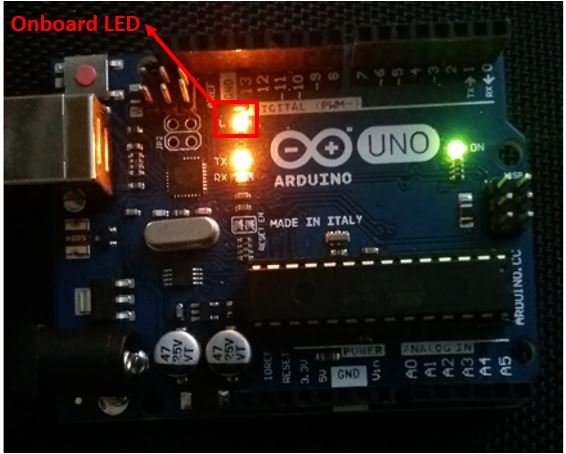
Now let us test the Timer1 and Timer2 interrupts. For Timer1 we will blink the onboard LED of Arduino UNO after every second. For Timer2 we will blink the onboard LED of Arduino UNO after every 0.5 s.
Calculations to find the Count value
- For Timer1:
System clock is 16Mhz and prescalar is 256 for generating clock of 1s
Speed of Timer1 = 16MHz/256 = 62.5 KHz
Pulse Time= 1/62.5 KHz = 16us
Hence value of OCR Register will be set to: 1s/16us = 62500
- For Timer2:
System clock is 16Mhz and prescalar is 1024 for generating clock of 10ms
Speed of Timer2 = 16MHz/1024 = 15.625 KHz
Pulse Time = 1/15.625 KHz = 64 us
Hence value of OCR register will be set to: 10ms/64us = 156.25 ->156 (whole number)
Arduino Sketch: Blinking onboard LED every second using Timer1 Interrupt
Open your Arduino IDE and go to File > New to open a new file. Copy the code given below in that file.
In the following sketch, Timer1 should generate an interrupt after every one second. The onboard LED will blink every second.
#include <avr/io.h>
#include <avr/interrupt.h>

const int LED_pin = 13;
unsigned int reload = 0xF424;
volatile int count;

ISR(TIMER1_COMPA_vect)
{
count++;
flash();
}
void setup()
{
Serial.begin(115200);
pinMode(LED_pin, OUTPUT);
digitalWrite(LED_pin, LOW);
cli();
TCCR1A = 0;
TCCR1B = 0;
OCR1A = reload;
TCCR1B = (1<<WGM12) | (1<<CS12);
TIMSK1 = (1<<OCIE1A);
sei();
Serial.println("TIMER1 Setup Finished.");
}
void loop()
{
Serial.println(count); // do anything
delay(200);
}
void flash()
{
static boolean output = HIGH;
digitalWrite(LED_pin, output);
output = !output;
}
How the Code Works?
In the ISR we will increase the count variable by 1 and toggle the state of the LED.
ISR(TIMER1_COMPA_vect)
{
count++;
flash();
}

void flash()
{
static boolean output = HIGH;
digitalWrite(LED_pin, output);
output = !output;
}
Inside, the setup() function, we will open the serial communication at a baud rate of 115200 and configure the onboard LED pin as an output. initially, we will set its state to LOW so that it will be OFF.
Serial.begin(115200);
pinMode(LED_pin, OUTPUT);
digitalWrite(LED_pin, LOW);
Then we will initialize the Timer1 registers. Reset the control registers by resetting TCCR1A and TCCR1B to 0.
TCCR1A = 0;
TCCR1B = 0;
The timer1 will be in CTC mode. We will set the value of compare register A to 0xF424 = 62500 as calculated previously. The ‘reload’ variable is defined at the start.
unsigned int reload = 0xF424;
OCR1A = reload;
Also, we will set the prescalar value by changing the bits of CS10, CS11 and CS12 in the following way.
TCCR1B = (1<<WGM12) | (1<<CS12);
TIMSK1 = (1<<OCIE1A);
Inside, the loop() function we will display the count variable in the serial monitor after every 200ms.
void loop()
{
Serial.println(count);
delay(200);
}
Demonstration
To see the demonstration of the above code, upload the code to Arduino. But, before uploading code, make sure to select the Arduino board from Tools > Board and also select the correct COM port to which the Arduino board is connected from Tools > Port.

Once the code is uploaded to Arduino, open the serial monitor and set the baud rate to 115200.
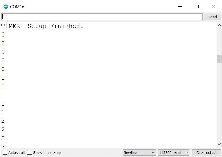
The onboard LED will start blinking every second.
Arduino Sketch: Blinking onboard LED every 0.5s using Timer2 Interrupt
Open your Arduino IDE and go to File > New to open a new file. Copy the code given below in that file.
In the following sketch, Timer2 should generate an interrupt after every 10 ms. The onboard LED will blink every half second.
#include <avr/io.h>
#include <avr/interrupt.h>

const int LED_pin = 13;
volatile byte count;
byte reload = 0x9C;

ISR(TIMER2_COMPA_vect)
{
count++;
OCR2A = reload;
}

void setup()
{
Serial.begin(115200);
pinMode(LED_pin, OUTPUT);
digitalWrite(LED_pin, LOW);
cli();
TCCR0B = 0;
OCR2A = reload;
TCCR2A = 1<<WGM21;
TCCR2B = (1<<CS22) | (1<<CS21) | (1<<CS20);
TIMSK2 = (1<<OCIE2A);
sei();
Serial.print("OCR2A: ");
Serial.println(OCR2A, HEX);
Serial.print("TCCR2A: ");
Serial.println(TCCR2A, HEX);
Serial.print("TCCR2B: ");
Serial.println(TCCR2B, HEX);
Serial.print("TIMSK2: ");
Serial.println(TIMSK2, HEX);
Serial.println("TIMER2 Setup Finished.");
}
void loop()
{
if (count == 50)
{
flash();
Serial.print(".");
count = 0;
}
}
void flash()
{
static boolean output = HIGH;
digitalWrite(LED_pin, output);
output = !output;
}
How the Code Works?
In the ISR we will increase the count variable by 1 and set the value of compare register A OCR2A to reload. The ‘reload’ variable was initially defined as ‘0xF424’ that is equal to 62500. This was calculated previously.
unsigned int reload = 0xF424;

ISR(TIMER2_COMPA_vect)
{
count++;
OCR2A = reload;
}
Inside, the setup() function, we will open the serial communication at a baud rate of 115200 and configure the onboard LED pin as an output. initially, we will set its state to LOW so that it will be OFF.
Serial.begin(115200);
pinMode(LED_pin, OUTPUT);
digitalWrite(LED_pin, LOW);
Then we will initialize the Timer2 registers and set it in CTC mode. Also, we will set the prescalar value by changing the bits of CS20, CS21 and CS22 as well.
TCCR0B = 0;
OCR2A = reload;
TCCR2A = 1<<WGM21;
TCCR2B = (1<<CS22) | (1<<CS21) | (1<<CS20);
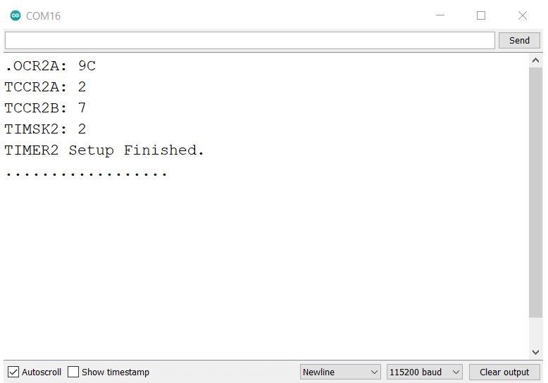
TIMSK2 = (1<<OCIE2A);In the serial monitor, we will display the bytes of Timer2 registers once the setup finishes.
Serial.print("OCR2A: ");
Serial.println(OCR2A, HEX);
Serial.print("TCCR2A: ");
Serial.println(TCCR2A, HEX);
Serial.print("TCCR2B: ");
Serial.println(TCCR2B, HEX);
Serial.print("TIMSK2: ");
Serial.println(TIMSK2, HEX);
Serial.println("TIMER2 Setup Finished.");
Inside the loop() function we will toggle the LED after every 0.5 s or 500ms. This will be achieved through an if statement which will check if the count has reached 50 or not. The count increments whenever an interrupt is caused after every 10ms. Thus when the count equals 50 that means the time is (50x10ms) = 500ms = 0.5s
void loop()
{
if (count == 50)
{
flash();
Serial.print(".");
count = 0;
}
}
void flash()
{
static boolean output = HIGH;
digitalWrite(LED_pin, output);
output = !output;
}
Demonstration
To see the demonstration of the above code, upload the code to Arduino. But, before uploading code, make sure to select the Arduino board from Tools > Board and also select the correct COM port to which the Arduino board is connected from Tools > Port.
Once the code is uploaded to Arduino, open the serial monitor and set the baud rate to 115200.
The onboard LED will start blinking every second.
Conclusion
In this guide, we have learned about Arduino timer interrupts and how to use Timer1 and Timer2 interrupts using Arduino IDE. We dedicated two sketches one for Timer1 and another for Timer2 where we demonstrated the interrupts through toggling the onboard LED. For Timer1, we set the clock to 1s. Every time the interruptions took place the state of the onboard LED was toggled. For Timer2, we set the clock to 10ms and toggled the LED after every 50 interruptions i.e. after every 0.5 seconds.
If I am not mistaking you mixed timer1 and timer2 in the table with the ‘Max Timer Period (ns)” and “Resolution (ms)” since timer1 is the one with 16bits
let us check again and correct it if it is wrong.
One of the timers doesn’t have a prescaler of 128. See table under “TimerSpeed”.
I found this tutorial and examples very enlightening. In conjunction with the
ATMEGA328 data sheet I’ve managed to achieve my objectives with the Timer/Counters.
As an inexperienced user though I noticed a few issues:
1. The first table has Timer1 and Timer2 swapped. Timer1 has a 16 bit counter and hence longer periods while Timer2 only has an 8 bit counter. Also, prescaler values 32 and 128 are not available in Timer1.
2. In the examples, the two “#include avr/…. ” compiler directives don’t appear to be necessary and should probably be of the form “#ifndef …. include …..”as the Arduino interface appears to already “#include” them.
3. As there are many abbreviations to take in it took me a while to work out that WGM12 and WGM21 set the timers in CTC mode. The data sheet implies that CTC1 may be an equivalent macro to WGM12 (Data sheet, Table 16.4, p121), but I haven’t tried that. (Doesn’t mention CTC2, table 18.8 though.)
4. In the Timer2 example, you set OCR2A in the ISR. It is not necessary to reload OCR2A as it is not affected by the CTC interrupt. At any Clear Timer on Compare interrupt, TCNTn is set to 0 and it all starts again with the existing Output Compare value, unless it is changed.
5. After the cli();, TCCR0B = 0; This refers to Timer0 and has no effect on Timer2 (but could probably interfere with other timer-based Arduino functions that rely on Timer0. You probably need a TCCR2B = 0 and TCCR2A = 0 for consistency.
6. I also observed that the timer-based macros (the ones in capitals) must have all their bits set/unset in the one command line else any settings made in previous commands are lost.
All in all, I enjoyed playing with the timers and this page was the most informative I found.