In this tutorial, you will learn how to use Arduino interrupts. First, we will see what are Arduino interrupts? After that we will see the general concepts of interrupts. We will see how to use interrupt service routine with Arduino. At the end of article, we will take two examples to demonstrate the effect and use of Arduino projects in real world embedded systems projects.
Recommended Components
The following components are used in this project or are helpful for building it with the Arduino.
| Component | How it’s used in this project | Buy on Amazon |
|---|---|---|
| Arduino Uno R3 | The main board that reads the interrupt pin and runs the interrupt service routine (ISR). | Check Price |
| Tactile push button | Wired to the interrupt pin to manually trigger the external interrupt in the examples. | Check Price |
| 5mm LED | Driven on pin 13 to show the interrupt firing (toggled inside the ISR). | Check Price |
| Resistor kit (220Ω) | A 220Ω series resistor protects the LED on the output pin. | Check Price |
| Breadboard | Solderless board to wire the button, LED and resistor to the Arduino. | Check Price |
| Jumper Wires | Connect the button, LED and resistor between the Arduino and breadboard. | Check Price |
As an Amazon Associate we earn from qualifying purchases. Prices and availability are accurate as of the date/time indicated and are subject to change.
What are interrupts?
Interrupts are the section of hardware and software on microcontroller which is capable of monitoring the external event on the input pin when any external event is monitor then the program is stop execution at this point and jump into their ISR function which is a interrupt handler then after executing the ISR function go back that point where the external event is monitor than it complete there execution.

Number of Arduino interrupts in different Arduino boards
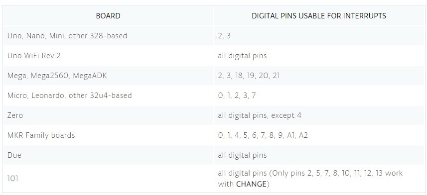
Different types of Arduino board have different numbers of interrupts pins e.g. Arduino UNO have two interrupt ports and Arduino Mega2560 have six interrupt ports named as INT1,INT0. On the software side create sleep mode for Arduino and use a timer base interrupts which would internally be essentially triggering awakening function and not relay on any external hardware.
How interrupts work?
So interrupts call an external function which is more commonly called an interrupts service routine or an ISR function. Interrupts service routine do have very specific constrains and do not behave exactly like some of the other functions that have been written for the Arduino.
What is a interrupt service routine?
Interrupt service routine (ISR) is also called an interrupts handler. There are many different type of interrupt handler which may handles many different types of interrupts like same as a simple example the clock in a system have its own interrupt handler same as the keyboard it also have its own interrupt handler for every device which is existing have its have its interrupt handler.
Generally ISR will use that something called a volatile variable which can still be used between other pieces of code also ISR should be short and fast as possible. Interrupts execute immediately if stop everything than program will currently doing in order to jump into the interrupts function and execute the code. Further more the interrupts will returns to the same point within the software where had perversely left off.
Basic Example of Arduino interrupts
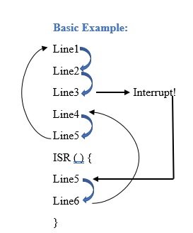
Above is the example of execution so line by line the code is execute until interrupt is called on Line3 then the function jumps down to the ISR and started executing the line5 and line 6 than after executing the lines within the ISR it jumps back to line4 and finishing the execution as routine. If it is in loop than go back to line1.
How interrupts are been triggered?
In Arduino interrupts, you can set how the interrupts are been triggered. There are five types of triggering Arduino interrupts:
- Change: When signal change even if signal rise or signal fall or if the signal is in low state at 0 or if the signal is in high state trigger 5v.
- Rising: On a rising edge the signal going from low to high means signal triggering from 0v to 5v.
- Falling: On a falling edge the signal going from high to low means signal is triggering from 5v to 0v.
- Low: Low is a continuous trigger whenever the signal is low in other words the signal is on 0v.
- High: High is a continuous trigger whenever the signal is high in other words the signal is on 5v.
The syntax which are going to be attach interrupt and specify the pin e.g. pin number 2 than ISR is the function which is going to be call and mode tells that whenever the interrupts is been triggered.
How to use Arduino interrupts?
Now lets see how to use Arduino interrupts functions already available in Arduino IDE to initialize Arduino interrupts and with which pin of Arduino you want to initialize it. Attach interrupt function is used for this purpose. This function takes two arguments as a input. one is a pin number to which pin you want to use for external interrupt triggering. Second argument is function name to which you want to call upon every interrupt. Last argument is the types of interrupt you are using. we have explained five types above.
attachInterrupt(digitalPinToInterrupt(pin), ISR, mode) ;For example:
attachInterrupt(digitalPinToInterrupt(2), InterruptFunction, Low) ;Example code of how to use Arduino interrupts
Below the example code of LED blinking in which the interrupt function is used to understand more clearly.
const byte ledPin = 13;Led is attach on the board of input pin 13.
const byte interruptPin = 2;A push button is attached on the interrupt pin 2.
volatile byte state = LOW;The state set to be at low
When the button pushed up then the interrupt is triggered and change the state if button is not pushed up then there is no change in the program and stay in the loop function.
void setup() {
   pinMode (ledPin, OUTPUT);
   pinMode (interruptPin , INPUT_PULLUP);
   attachInterrupt (digitalPinToInterrupt (interruptPin ), glow, CHANGE ) ;
}
With the help of this function the interrupt is attached in the code. Three parameters are presents in attachInterrupt function the 1st is interrupt pin in the care of this example the interrupt pin is 2, and the 2nd is ISR function which is named as Glow, and the 3rd is mode in this example the mode is set to change mode means whenever the interrupt trigger even if interrupt rise or fall and low or high at any condition interrupt triggered.
void loop ( ) {
   digitalWrite (ledPin, state ) ;
}
led set on the digital pin 13.When the interrupt call then level triggered and change is position than Led will glow up. Glow is the function of interrupt service routing.
void glow ( ) {
   state = !state ;
}
This line changes the state of LED whenever the button is pushed or the interrupts called.
Complete code is given below:
const byte ledPin = 13 ;

const byte interruptPin = 2 ;

volatile byte state = LOW ;

void setup ( ) {

   pinMode ( ledPin , OUTPUT ) ;

   pinMode ( interruptPin , INPUT_PULLUP) ;

   attachInterrupt ( digitalPinToInterrupt ( interruptPin ), glow, CHANGE ) ;

}

void loop ( ) {

   digitalWrite ( ledPin, state ) ;.

}

void glow ( )

{

   state = !state ;

}
Example code 2 of Arduino interrupts with falling edge
int ledpin = 13 ;
int y = 0 ;

Void setup ( ) {

attachInterrupt ( 0, increment, Falling);
Serial.begin (9600 );

}

void loop ( ) {

digitalWrite(ledPin, LOW) ;
delay(3000) ;
Serial.println(y, DEC) ;

}

Void increment ( ) {
Y++ ;
digitalWrite ( ledPin, HIGH) ;

}
LED is attached to digital pin 13 in Arduino board
int ledpin = 13 ;Variable to be updated by the interrupt
int y = 0 ;Enable interrupt 0 on pin 2 which is connected to a button
Void setup ( ) {
attachInterrupt ( 0, increment, Falling);
Jump to the increment function on falling edge
Serial.begin (9600 );It turn on the serial communication
It required interrupts to works but when the delay is inside the ISR function so it not able to works.
void loop ( ) {
digitalWrite(ledPin, LOW);
delay(3000);
Print y to serial monitor
Serial.println(y, DEC);ISR function for interrupt 0
Void increment ( ) {
Y++;
digitalWrite (ledPin, HIGH);
When the code is start execution and the variable y is incremented then the LED is turned on and after that the program return back to the main loop wherever it was break when the interrupt comes.
Respected sir, i’m beginers for arduino . I taken code from here and put in arduino ide and try to compile, then we get error. Why is this
There is a typo. Remove the stray period after
digitalWrite ( ledPin, state ) ;
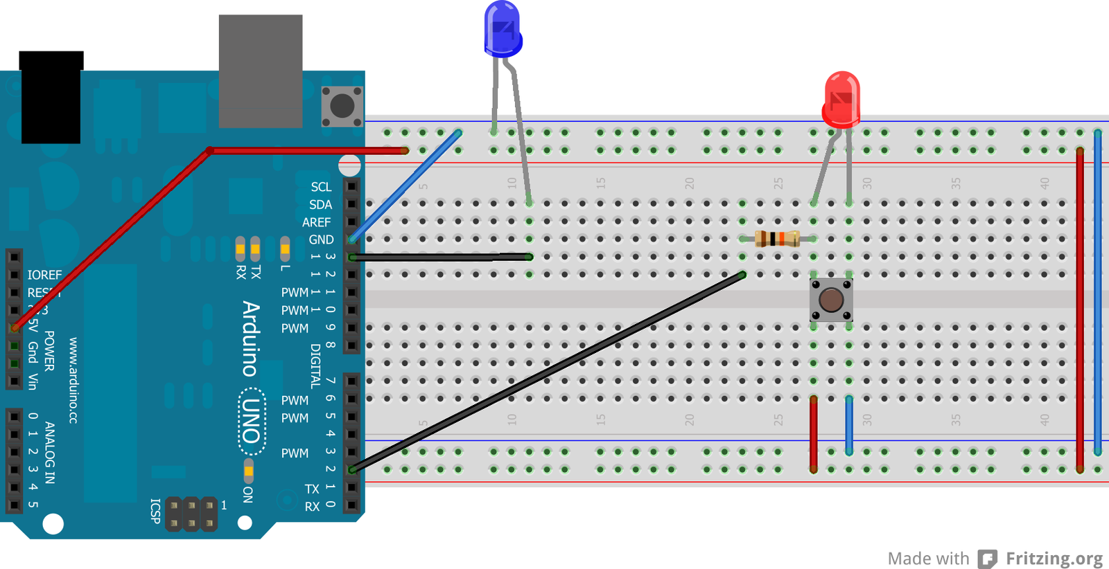
Correct me if I’m wrong but in the example it seems that when the switch is closed, the circuit is shorted and 5V (red) is connected directly to GND (blue). No resistor between!
There is a resistor.
Based on the image:
The resistor is not connected to the red LED, and so Chris is correct: the LED is receiving too much current: nearly 500 mA (the maximum it should be getting is 20 mA).
Instead, the resistor is connected to pin 2, rather than the red LED.
1 KiloOhms (the resistance of the resistor in the image) is a little much for the LEDs; 220 Ohms should be plenty.
The blue LED should have a resistor between its Anode and pin 13, otherwise it is receiving over 50 mA, when the maximum number of mA an LED should be receiving is 20 mA.
The push button is also used incorrectly. As it currently is setup, the red LED is constantly receiving power, as the push button connects its pins from left-to-right, not top-to-bottom. Pushing the button does nothing.
Hi Joshua,
Yes, you are right, and thanks for pointing out mistakes. We will update the article with the correct circuit diagram.
I DID NOT GET THE CODE IN THE TUTORIAL.. I WOULD BE VERY HAPPY IF THIS WAS THERE TO TRY.
THANKS
A lot of helpful information. But did you run the simulation on Fritzing with HW and code?