This tutorial will teach you how to capture and save a photo using the ESP32-CAM module onto a MicroSD card, including a timestamp as a filename with the current date and time. The image will be saved with a filename consisting of the date and time it was taken. ESP32 will get updated time from an NTP server.
In our previous article on ESP32-CAM where we took a photo with the module and saved it to a MicroSD card using an incremented index as a filename to differentiate between each image. Using a filename that includes the date and time makes it simpler to identify when the picture was taken.
Project Overview
The following diagram shows a high-level overview of this project:
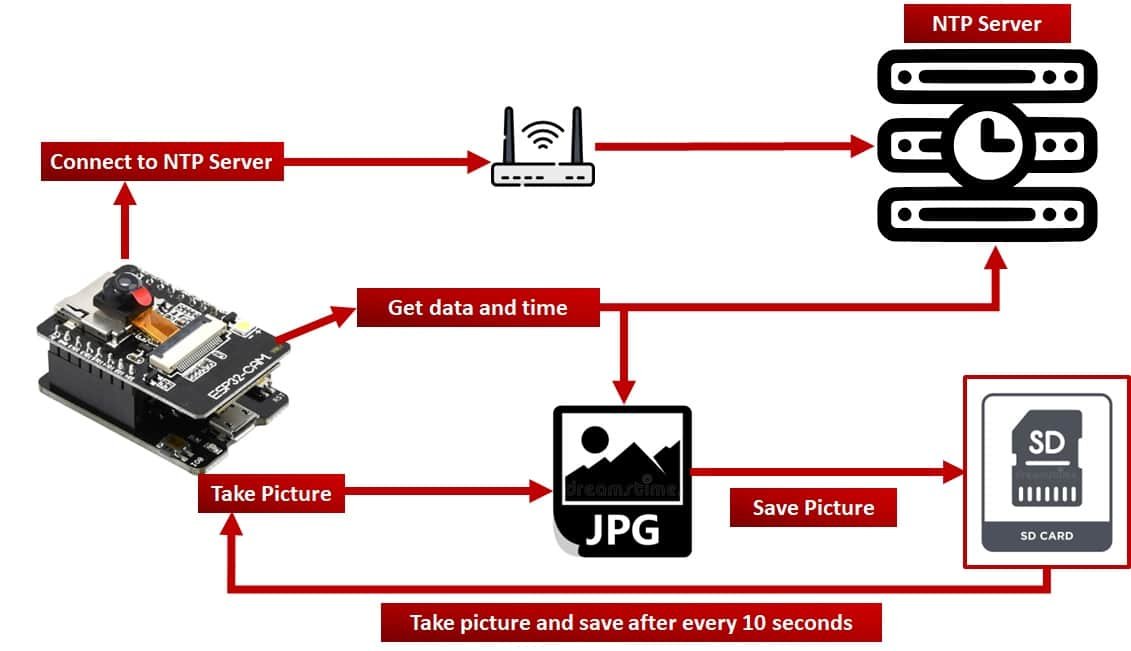
This tutorial provides a straightforward example that demonstrates the following steps:
- The ESP32-CAM gets a Wi-Fi connection to your router to obtain time from an NTP server.
- Connects to the NTP server to synchronize the date and time in the correct time zone.
- Initialize MicroSD card to save pictures
- Take a new picture and get the current date and time from the NTP server.
- set the filename of a picture according to current data and time
- save the picture to a MicroSD card
- Repeat the above steps after every 10 seconds
For this project, we will ESP32-CAM AI Thinker board. But you can use any type of ESP32-CAM development board, you just need to change pin configuration in the code accordingly.
We will be using Arduino IDE to program ESP32-CAM AI Thinker board. If you have not used ESP32 with Arduino IDE before, you need to install an ESP32 library in Arduino by following this guide:
If you are just started using ESP32-CAM, you can refer to these getting-started guides:
- ESP32-CAM AI-Thinker Board – All about GPIO Pins
- ESP32-CAM Take Photo and Display in Web Server
- ESP32-CAM Take and Send Photos via Email using an SMTP Server
As mentioned earlier, we will save photos to a MicroSD card with a timestamp used as a filename of each picture. Before inserting your MicroSD card into the ESP32-CAM module make sure to format it with FAT32 filesystem format.
If you want to get familiarized with the use of a MicroSD card with ESP32 and how to perform file read and operations, you can read the following guide:
Furthermore, we will use an NTP server to get the most up-to-date time and date information according to our timezone and sync the ESP32 time with the corresponding NTP server values.
To learn how to retrieve the current date and time from the NTP server using the ESP32 development board and Arduino IDE, you can refer to the following guide:
Connecting ESP32-CAM with FTDI programmer
We will require the following components for this project:
- ESP32-CAM development board
- FTDI Programmer/ USB Serial to TTL Converter
- Connecting Wires
- External 5V power supply (optional)
Unlike the ESP32 development board, the ESP32-CAM does not come with a USB port attached to it. So to upload a program sketch to the ESP32-CAM, we will need to use an FTDI programmer (USB to TTL Serial converter).
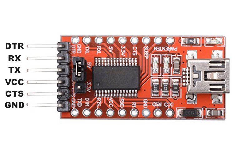
You can learn more about this FTDI cable here:
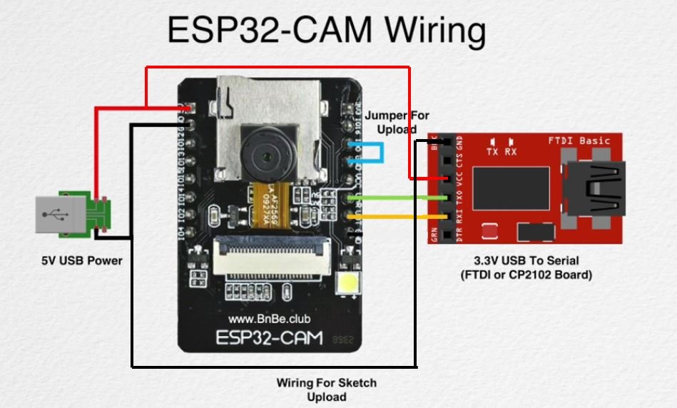
The table shows the connections between the ESP32-CAM and FTDI programmer:
| ESP32-CAM | FTDI Programmer |
|---|---|
| 5V | VCC |
| UOR (GPIO3) | TX |
| UOT (GPIO1) | RX |
| GND | GND |
Connect the 5V pin of ESP32-CAM with the VCC pin of the FTDI programmer to power up. Both grounds of the two devices will be connected in common. The TX pin of the FTDI programmer will be connected with UOR (GPIO3) of ESP32-CAM. Likewise, the RX pin will be connected with the UOT (GPIO1) of the ESP32-CAM module.
Additionally, you will need to connect GPIO0 with GND to enable the ESP32-CAM module to go in flashing mode. Remove this connection after uploading the program sketch to the module.
On some ESP32-CAM boards, you will get a brown-out detector error which is due to the insufficient voltage provided by the FTDI cable. In that case, you should connect an external 5V power supply to ESP32 as shown below:
ESP32-CAM Code
This ESP32-CAM code takes a photo after every 10 seconds and saves it to an SD card. It also connects to a WiFi network to set the time zone and synchronize the ESP32 time using an NTP server. Furthermore, it sets the filename for the photo based on the current updated time from NTP server.
#include "esp_camera.h"
#include "FS.h"                // SD Card ESP32
#include "SD_MMC.h"            // SD Card ESP32
#include "soc/soc.h"           // Disable brownout problems
#include "soc/rtc_cntl_reg.h"  // Disable brownout problems
#include "driver/rtc_io.h"
#include <WiFi.h>
#include "time.h"

const char* my_ssid = "Replace_with_your_ssid";
const char* my_password = "replace_with_your_password";

String time_zone ="PKT-5";

#define PWDN_GPIO_NUM     32
#define RESET_GPIO_NUM    -1
#define XCLK_GPIO_NUM      0
#define SIOD_GPIO_NUM     26
#define SIOC_GPIO_NUM     27
#define Y9_GPIO_NUM       35
#define Y8_GPIO_NUM       34
#define Y7_GPIO_NUM       39
#define Y6_GPIO_NUM       36
#define Y5_GPIO_NUM       21
#define Y4_GPIO_NUM       19
#define Y3_GPIO_NUM       18
#define Y2_GPIO_NUM        5
#define VSYNC_GPIO_NUM    25
#define HREF_GPIO_NUM     23
#define PCLK_GPIO_NUM     22

camera_config_t config;

void init_camera_pins(){
  config.ledc_channel = LEDC_CHANNEL_0;
  config.ledc_timer = LEDC_TIMER_0;
  config.pin_d0 = Y2_GPIO_NUM;
  config.pin_d1 = Y3_GPIO_NUM;
  config.pin_d2 = Y4_GPIO_NUM;
  config.pin_d3 = Y5_GPIO_NUM;
  config.pin_d4 = Y6_GPIO_NUM;
  config.pin_d5 = Y7_GPIO_NUM;
  config.pin_d6 = Y8_GPIO_NUM;
  config.pin_d7 = Y9_GPIO_NUM;
  config.pin_xclk = XCLK_GPIO_NUM;
  config.pin_pclk = PCLK_GPIO_NUM;
  config.pin_vsync = VSYNC_GPIO_NUM;
  config.pin_href = HREF_GPIO_NUM;
  config.pin_sscb_sda = SIOD_GPIO_NUM;
  config.pin_sscb_scl = SIOC_GPIO_NUM;
  config.pin_pwdn = PWDN_GPIO_NUM;
  config.pin_reset = RESET_GPIO_NUM;
  config.xclk_freq_hz = 20000000;
  config.pixel_format = PIXFORMAT_JPEG; //YUV422,GRAYSCALE,RGB565,JPEG
  config.grab_mode = CAMERA_GRAB_LATEST;

  if(psramFound()){
    config.frame_size = FRAMESIZE_UXGA; // FRAMESIZE_ + QVGA|CIF|VGA|SVGA|XGA|SXGA|UXGA
    config.jpeg_quality = 10; //0-63 lower number means higher quality
    config.fb_count = 1;
  } else {
    config.frame_size = FRAMESIZE_SVGA;
    config.jpeg_quality = 12;
    config.fb_count = 1;
  }

  esp_err_t err = esp_camera_init(&config);
  if (err != ESP_OK) {
    Serial.printf("ESP32 CAM init failed with error 0x%x", err);
    return;
  }
}

void  connect_wifi(){
  WiFi.begin(my_ssid, my_password);
  Serial.println("Connecting to Wi-Fi");
  while (WiFi.status() != WL_CONNECTED) {
    Serial.print(".");
    delay(500);
  }
}

void set_time_zone(String timezone){
  Serial.printf("  Setting Timezone to %s\n",timezone.c_str());
  setenv("TZ",timezone.c_str(),1);  //  Now adjust the TZ.  Clock settings are adjusted to show the new local time
  tzset();
}

void get_ntp_time(String timezone){
  struct tm timeinfo;
  Serial.println("Getting time from NTP Server");
  configTime(0, 0, "pool.ntp.org");    // First connect to NTP server, with 0 TZ offset
  if(!getLocalTime(&timeinfo)){
    Serial.println(" Failed to get time from NTP");
    return;
  }
  Serial.println("Successfully received time from NTP");
  set_time_zone(timezone);
}

String set_pic_name_time_stamp(){
  struct tm timeinfo;
  if(!getLocalTime(&timeinfo)){
    Serial.println("Failed to get time");
    return "";
  }
  char timeString[20];
  strftime(timeString, sizeof(timeString), "%Y-%m-%d_%H-%M-%S", &timeinfo);
  Serial.println(timeString);
  String filename = "/picture_" + String(timeString) +".jpg";
  return filename;
}

void init_sd_card(){
  Serial.println("Starting SD Card");
  if(!SD_MMC.begin()){
    Serial.println("SD Card Mount Failed");
    return;
  }
  uint8_t cardType = SD_MMC.cardType();
  if(cardType == CARD_NONE){
    Serial.println("No SD Card attached");
    return;
  }
}

void take_photo_and_save(){
  camera_fb_t * fb = esp_camera_fb_get();


  if(!fb) {
    Serial.println("Camera capture failed");
    delay(1000);
    ESP.restart();
  }

  String path = set_pic_name_time_stamp();
  Serial.printf("Picture file name: %s\n", path.c_str());

  fs::FS &fs = SD_MMC;
  File file = fs.open(path.c_str(),FILE_WRITE);
  if(!file){
    Serial.printf("Failed to open file in writing mode");
  }
  else {
    file.write(fb->buf, fb->len); // payload (image), payload length
    Serial.printf("Saved: %s\n", path.c_str());
  }
  file.close();
  esp_camera_fb_return(fb);
}

void setup() {
  WRITE_PERI_REG(RTC_CNTL_BROWN_OUT_REG, 0); // disable brownout detector

  Serial.begin(115200);
  delay(2000);

  connect_wifi();
  get_ntp_time(time_zone);
  Serial.print("Initializing ESP32 camera module...");
  init_camera_pins();
  Serial.println("Ok!");
  Serial.print("Initializing the Micro SD card module... ");
  init_sd_card();
}

void loop() {
  take_photo_and_save();
  delay(10000);
}
How does Code work?
These lines include several libraries and header files that are required for an ESP32-based project involving a camera control, SD card, WiFi connectivity, and time synchronization.
#include "esp_camera.h"
#include "FS.h"                // SD Card ESP32
#include "SD_MMC.h"            // SD Card ESP32
#include "soc/soc.h"           // Disable brownout problems
#include "soc/rtc_cntl_reg.h"  // Disable brownout problems
#include "driver/rtc_io.h"
#include <WiFi.h>
#include "time.h"
Define two const character strings to store Wi-Fi ssid and password. Replace the value of these constant strings with your Wi-Fi router SSID and password.
const char* my_ssid = "Replace_with_your_ssid";
const char* my_password = "replace_with_your_password";
Define a variable named time_zone of type String. The value of this variable is the string “PKT-5”, which likely represents the time zone for a particular location. You should replace the time zone value according to your time zone. You can follow this link to get timezone from your country.
String time_zone ="PKT-5";Initialize ESP32-CAM AI Thinker Pins
Define the pin configuration for ESP32‑CAM AI-Thinker module Camera pins. The following definitions are for OV2640 camera module pins which come with ESP32-CAM AI Thinker module.
Each #defiine preprocessor directive represents the GPIO pin number that is connected to a specific pin of a camera module. For example, PWDN_GPIO_NUM represents the GPIO pin number that is connected to the “power down” pin, while Y7_GPIO_NUM (GPIO36 of ESP32) represents the GPIO pin number that is connected to the Y7 pin of the camera module and similarly for other pins.
#define PWDN_GPIO_NUM     32
#define RESET_GPIO_NUM    -1
#define XCLK_GPIO_NUM      0
#define SIOD_GPIO_NUM     26
#define SIOC_GPIO_NUM     27
#define Y9_GPIO_NUM       35
#define Y8_GPIO_NUM       34
#define Y7_GPIO_NUM       39
#define Y6_GPIO_NUM       36
#define Y5_GPIO_NUM       21
#define Y4_GPIO_NUM       19
#define Y3_GPIO_NUM       18
#define Y2_GPIO_NUM        5
#define VSYNC_GPIO_NUM    25
#define HREF_GPIO_NUM     23
#define PCLK_GPIO_NUM     22
The init_camera_pins() function initializes the camera pins by assigning specific GPIO numbers of ESP32 to the different camera data and control pins. It sets the LEDC channel and timer used for PWM output, pixel format for the camera output, frame size, and quality for JPEG encoding.
If a PSRAM module is detected, the frame size is set to UXGA and the JPEG quality is set to 10. Otherwise, the frame size is set to SVGA and the JPEG quality is set to 12. Finally, the camera grab mode is set to CAMERA_GRAB_LATEST.
camera_config_t config;

void init_camera_pins(){
  config.ledc_channel = LEDC_CHANNEL_0;
  config.ledc_timer = LEDC_TIMER_0;
  config.pin_d0 = Y2_GPIO_NUM;
  config.pin_d1 = Y3_GPIO_NUM;
  config.pin_d2 = Y4_GPIO_NUM;
  config.pin_d3 = Y5_GPIO_NUM;
  config.pin_d4 = Y6_GPIO_NUM;
  config.pin_d5 = Y7_GPIO_NUM;
  config.pin_d6 = Y8_GPIO_NUM;
  config.pin_d7 = Y9_GPIO_NUM;
  config.pin_xclk = XCLK_GPIO_NUM;
  config.pin_pclk = PCLK_GPIO_NUM;
  config.pin_vsync = VSYNC_GPIO_NUM;
  config.pin_href = HREF_GPIO_NUM;
  config.pin_sscb_sda = SIOD_GPIO_NUM;
  config.pin_sscb_scl = SIOC_GPIO_NUM;
  config.pin_pwdn = PWDN_GPIO_NUM;
  config.pin_reset = RESET_GPIO_NUM;
  config.xclk_freq_hz = 20000000;
  config.pixel_format = PIXFORMAT_JPEG; //YUV422,GRAYSCALE,RGB565,JPEG
  config.grab_mode = CAMERA_GRAB_LATEST;

  if(psramFound()){
    config.frame_size = FRAMESIZE_UXGA; // FRAMESIZE_ + QVGA|CIF|VGA|SVGA|XGA|SXGA|UXGA
    config.jpeg_quality = 10; //0-63 lower number means higher quality
    config.fb_count = 1;
  } else {
    config.frame_size = FRAMESIZE_SVGA;
    config.jpeg_quality = 12;
    config.fb_count = 1;
  }
 esp_err_t err = esp_camera_init(&config);
  if (err != ESP_OK) {
    Serial.printf("ESP32 CAM init failed with error 0x%x", err);
    return;
  }
}
The ESP32-CAM can take pictures and save them in one of the following formats. We have set the image format to PIXFORMAT_JPEG in this tutorial as shown in the above code snippet.
PIXFORMAT_JPEG
PIXFORMAT_YUV422
PIXFORMAT_GRAYSCALE
PIXFORMAT_RGB565
PIXFORMAT_JPEG (format that we’re using)
These lines set the camera resolution (frame_size), JPEG quality (jpeg_quality), and frame buffer count (fb_count). If your ESP32-CAM module has PSRAM support, the frame size will be set to FRAMESIZE_UXGA (ultra extended graphics array) with lower JPEG quality, otherwise, the frame size will be set to FRAMESIZE_SVGA (super VGA) with higher JPEG quality. The frame buffer count is always set to 1.
if(psramFound()){
    config.frame_size = FRAMESIZE_UXGA; // FRAMESIZE_ + QVGA|CIF|VGA|SVGA|XGA|SXGA|UXGA
    config.jpeg_quality = 10; //0-63 lower number means higher quality
    config.fb_count = 1;
  } else {
    config.frame_size = FRAMESIZE_SVGA;
    config.jpeg_quality = 12;
    config.fb_count = 1;
  }
Additionally, we can set the frame size to one of the following if ESP32-CAM module has PSRAM support:
FRAMESIZE_UXGA (1600 x 1200)
FRAMESIZE_QVGA (320 x 240)
FRAMESIZE_CIF (352 x 288)
FRAMESIZE_VGA (640 x 480)
FRAMESIZE_SVGA (800 x 600)
FRAMESIZE_XGA (1024 x 768)
FRAMESIZE_SXGA (1280 x 1024)
Initialize ESP32-CAM AI thinker module with esp_camera_init() function. The esp_camera_init() function initializes the camera driver with the given configuration settings.
The esp_err_t is a data type that represents the error status returned by functions in the ESP-IDF framework. A err will store the error status returned by the esp_camera_init() function. In other words, if the camera is not initialized successfully, it will return an error.
 esp_err_t err = esp_camera_init(&config);
  if (err != ESP_OK) {
    Serial.printf("ESP32 CAM init failed with error 0x%x", err);
    return;
  }
}
Define the connect_wifi() function which connects ESP32-CAM AI Thinker module to a Wi-Fi network using the SSID and password stored in the variables my_ssid and my_password respectively.
It prints the message “Connecting to Wi-Fi” on the serial monitor. After that, it will start a loop that will continue until the Wi-Fi connection is established. The WL_CONNECTED is a constant that indicates that the Wi-Fi connection has been established. Once the connection to the Wi-Fi network is established, the function will exit.
void  connect_wifi(){
  WiFi.begin(my_ssid, my_password);
  Serial.println("Connecting to Wi-Fi");
  while (WiFi.status() != WL_CONNECTED) {
    Serial.print(".");
    delay(500);
  }
}
Set and Get Timer from NTP Server
The set_time_zone() function sets the time zone of ESP32 according to input parameter of the function.
void set_time_zone(String timezone){
  Serial.printf("  Setting Timezone to %s\n",timezone.c_str());
  setenv("TZ",timezone.c_str(),1);  //  Now adjust the TZ.  Clock settings are adjusted to show the new local time
  tzset();
}
It sets the environment variable “TZ” to the provided timezone value using the setenv() function. The second argument 1 tells the function to overwrite any previous value of the “TZ” environment variable.
setenv("TZ",timezone.c_str(),1); // Now adjust the TZ. Clock settings are adjusted to show the new local timeCall tzset() function to update the time zone based on the new value of the “TZ” environment variable. This will affect the behavior of various time-related functions in the program, such as time(), localtime(), gmtime(), and strftime()
tzset();The get_ntp_time function connects ESP32-CAM module to an NTP server and gets updated time from an NTP server.
The configTime() function configures the timezone and NTP server for the ESP32’s system clock. It takes three arguments: the first one is the timezone offset in seconds (here set to 0); the second one is the daylight saving time offset (not used here); and the third one is the NTP server name.
After configuring time zone, the getLocalTime() function retrieves the current date and time from the ESP32 system clock and stores it in the timeinfo variable. If it fails (returns false), an error message is printed and the function returns.
void get_ntp_time(String timezone){
  struct tm timeinfo;
  Serial.println("Getting time from NTP Server");
  configTime(0, 0, "pool.ntp.org");    // First connect to NTP server, with 0 TZ offset
  if(!getLocalTime(&timeinfo)){
    Serial.println(" Failed to get time from NTP");
    return;
  }
  Serial.println("Successfully received time from NTP");
  set_time_zone(timezone);
}
Generate Picture File Name with Timestamp
This set_pic_name_time_stamp function generates a timestamp string in the format of year-month-day_hour-minute-second based on the current local time. It then returns a string with the filename “picture_” followed by the timestamp and “.jpg”.
String set_pic_name_time_stamp()
{
  struct tm timeinfo;
  if(!getLocalTime(&timeinfo)){
    Serial.println("Failed to get time");
    return "";
  }
  char timeString[20];
  strftime(timeString, sizeof(timeString), "%Y-%m-%d_%H-%M-%S", &timeinfo);
  Serial.println(timeString);
  String filename = "/picture_" + String(timeString) +".jpg";
  return filename;
}
Declares a variable called timeinfo of type struct tm, which is a C structure that holds date and time values.
struct tm timeinfo;Call the getLocalTime function to get the current date and time information, and saves the result in the timeinfo variable. If the getLocalTime() function returns false, indicating that it failed to get the time, the function prints an error message to the serial monitor and returns an empty string.
 if(!getLocalTime(&timeinfo)){
    Serial.println("Failed to get time");
    return "";
  }
Declare a character array called timeString that can hold 20 characters.
char timeString[20];Formats the date and time information stored in timeinfo as a string in the format of “%Y-%m-%d_%H-%M-%S”. This format represents the year, month, and day separated by dashes, followed by the hour, minute, and second separated by colons. The resulting string is stored in timeString.
strftime(timeString, sizeof(timeString), "%Y-%m-%d_%H-%M-%S", &timeinfo);Finally, construct a String object called filename by concatenating the string “/picture_”, the formatted date and time string stored in timeString, and the file extension “.jpg”. The resulting string is stored in the filename variable.
String filename = "/picture_" + String(timeString) +".jpg";Return the filename string to the calling function.
return filename; Initialize microSD Card
This init_sd_card() function initializes the SD card and checks if it is properly mounted. If the SD card is not mounted or no SD card is attached, it will print an error message and return.
void init_sd_card(){
  Serial.println("Starting SD Card");
  if(!SD_MMC.begin()){
    Serial.println("SD Card Mount Failed");
    return;
  }
  uint8_t cardType = SD_MMC.cardType();
  if(cardType == CARD_NONE){
    Serial.println("No SD Card attached");
    return;
  }
}
Take Picture and Save to SD Card with Timestamp
The take_photo_and_save() function captures a photo using the ESP32-CAM AI Thinkder module camera and saves it to an SD card with a filename as the current date and time. The captured image is written to the file with the path obtained from the function set_pic_name_time_stamp(). If the image is successfully written to the file, a success message is printed; otherwise, an error message is printed.
void take_photo_and_save(){
  camera_fb_t * fb = esp_camera_fb_get();


  if(!fb) {
    Serial.println("Camera capture failed");
    delay(1000);
    ESP.restart();
  }

  String path = set_pic_name_time_stamp();
  Serial.printf("Picture file name: %s\n", path.c_str());

  fs::FS &fs = SD_MMC;
  File file = fs.open(path.c_str(),FILE_WRITE);
  if(!file){
    Serial.printf("Failed to open file in writing mode");
  }
  else {
    file.write(fb->buf, fb->len); // payload (image), payload length
    Serial.printf("Saved: %s\n", path.c_str());
  }
  file.close();
  esp_camera_fb_return(fb);
}
Declare a pointer fb of type camera_fb_t and assigns it the value returned by the function esp_camera_fb_get(). In other words, esp_camera_fb_get() function takes an image and points the image content pointer to fb buffer.
camera_fb_t * fb = esp_camera_fb_get();This if statement checks if fb is null (i.e., if the camera capture failed). If it is null, the function prints an error message, waits for 1 second and then restarts the ESP board.
if(!fb) {
    Serial.println("Camera capture failed");
    delay(1000);
    ESP.restart();
  }
Get the file name from the set_pic_name_time_stamp() function and save it to the path string.
String path = set_pic_name_time_stamp();
Serial.printf("Picture file name: %s\n", path.c_str());
After getting the picture buffer and file name, let’s save the picture to a MicroSD card. Create a reference fs of type fs::FS and assigns it to the SD_MMC object, which represents the SD card. Opena a file on the SD card in writing mode with the file name specified by the path variable.
If ESP32-CAM is failed to open a file with the given name path, print an error. Otherwise, save the image buffer to a file with a file.write() function and pass it fb buffer content and its length.
 fs::FS &fs = SD_MMC;
  File file = fs.open(path.c_str(),FILE_WRITE);
  if(!file){
    Serial.printf("Failed to open file in writing mode");
  }
  else {
    file.write(fb->buf, fb->len); // payload (image), payload length
    Serial.printf("Saved: %s\n", path.c_str());
  }
Finally, close the file and clear the memory allocated for the buffer by calling esp_camera_fb_return() function.
  file.close();
  esp_camera_fb_return(fb);
Setup Function
The setup() function performs several initializations for the ESP32-CAM AI Thinker project. It starts by disabling the brownout detector, initializes the serial communication, connecting to Wi-Fi, setting the time using NTP, initializing the camera module, and finally initializing the Micro SD card module. The function provides status updates during the initialization process through Serial.println() statements.
void setup() {
  WRITE_PERI_REG(RTC_CNTL_BROWN_OUT_REG, 0); // disable brownout detector

  Serial.begin(115200);
  delay(2000);

  connect_wifi();
  get_ntp_time(time_zone);
  Serial.print("Initializing ESP32 camera module...");
  init_camera_pins();
  Serial.println("Ok!");
  Serial.print("Initializing the Micro SD card module... ");
  init_sd_card();
}
Inside loop() function, repeatedly takes a photo using the ESP32-CAM module and saves it to the SD card every 10 seconds.
void loop() {
  take_photo_and_save();
  delay(10000);
}
Uploading and Demonstration
Now, we are ready to compile and upload the code to our ESP32-CAM. Make sure the FTDI programmer is properly connected with the module and GPIO0 is grounded as well.
Choose the correct board and COM port before uploading your code to the ESP32-CAM board. Go to Tools > Board and select ESP32 AI Thinker.
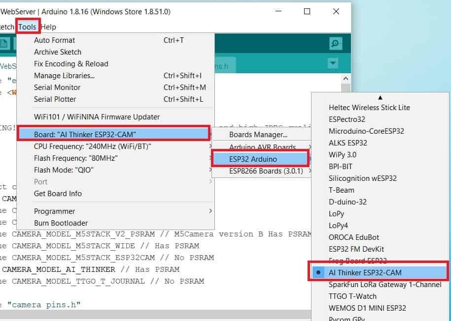
Next, go to Tools > Port and select the appropriate port through which your board is connected.
Click on the upload button to upload the code into the ESP32-CAM board.
If you view Connecting….._____….._____….. in the error window, press the RESET button present on the ESP32-CAM as shown below:

After you have successfully uploaded your code to the board, remove the connecting wire from GPIO0 and GND.
Now open the serial monitor and press the RESET button on the ESP32-CAM AT Thinker module.
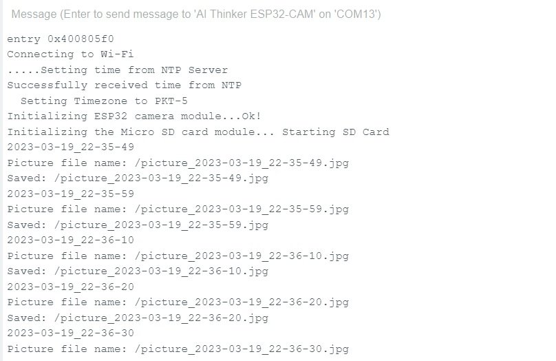
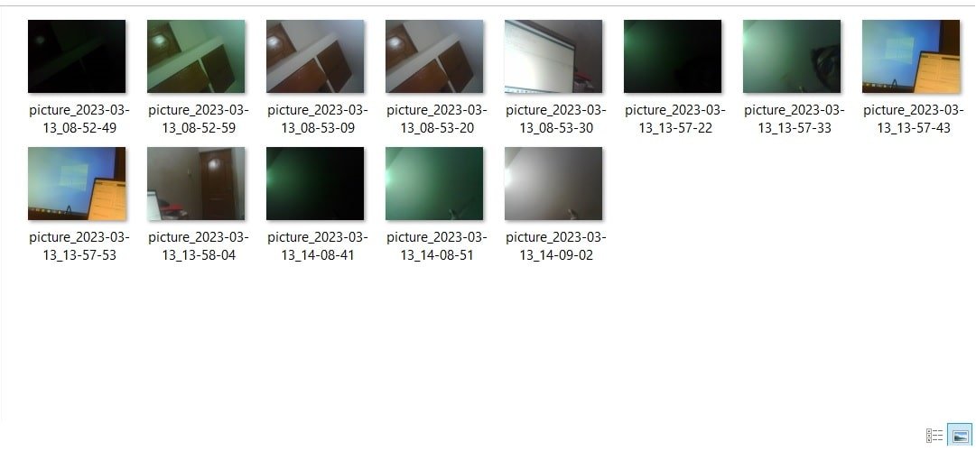
Take the microSD card out of ESP32-CAM module and insert it into your system to view all the images. Here, you can see pictures are saved into a MicroSD card and each picture has data and time as its name.
In summary:
In this ESP32-CAM project, we learned how to take photos and save them to a micro SD card. We also learned to connect ESP32 with an NTP server and retrieve the current time from an NTP server. The camera takes photos every 10 seconds and saves them to the SD card using a timestamped filename.
You may also like to read:
I ‘d like the projet you have