In this tutorial, we will learn how to interface RFID reader RDM6300 or RDM630 with ESP32 development board. Both of these RFID readers communicate via a serial connection on UART and follow the same interfacing with ESP32 thus this tutorial will be compatible with both types of RFID readers. First, we will give you a brief description of the RDM6300 module which is cheaper than RDM630 and easily available, its pinout and connection with the ESP32 board. Then we will show you a sketch which will enable us to identify EM4100-compatible tags via this RFID reader.
We have a similar guide with Arduino and ESP32:
Recommended Components
The following components are used in this project or are helpful for building it with the ESP32.
| Component | How it’s used in this project | Buy on Amazon |
|---|---|---|
| ESP32 Development Board | Reads the RFID tag IDs from the reader over UART. | Check Price |
| Micro USB Cable | Programs the ESP32 and powers it during testing. | Check Price |
| Breadboard | Holds the reader module and wiring without soldering. | Check Price |
| Jumper Wires | Connect the UART and power lines between the ESP32 and the reader. | Check Price |
| RDM6300/RDM630 RFID reader | 125 kHz RFID reader that sends scanned tag IDs to the ESP32 over serial. | Check Price |
As an Amazon Associate we earn from qualifying purchases. Prices and availability are accurate as of the date/time indicated and are subject to change.
RDM6300 RFID reader
RFID stands for Radio Frequency Identification. It is a tagging identification system that uses electromagnetic waves in radio frequency to transfer data. An RFID system consists of a passive card or tag and an active read or write device which is RDM6300 in our case.
RDM6300 RFID module is a low-cost RFID reader. You can purchase it for less than 5$ as compared to RDM630 which costs approximately $10-15. Both of the modules work on a 125kHz radio frequency. Therefore, they are able to detect RFID tags or cards which can communicate with RFID readers at 125KHz frequency. RDM6300 RFID module works on transistor logic or in short TTL logic. It means you need to provide 5 volt dc to power supply pins of this module. It has a UART communication function. In other words, it can communicate with microcontroller through a UART serial communication. It has TTL RS232 format.
Note: RDM6300 can only read data from 125KHz tags or cards.
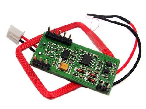
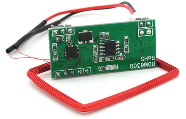
Below you can view the two RDM630 and RDM6300 modules:

RDM630 
RDM6300
Pin configuration of RDM6300 RFID reader module
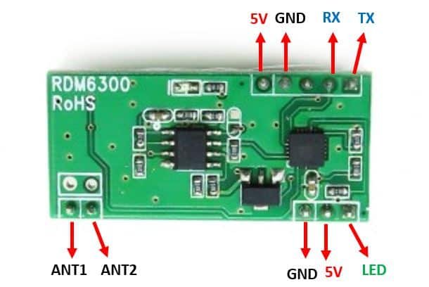
The RDM6300 module consists of 10 pins out of which only 5 pins are required to interface this RFID tag reader with the microcontroller. You can view the pinout below:
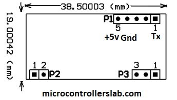
The RDM6300 module consists of three headers as shown above. Details of P1 header pins are given below:
| Pin | Description |
|---|---|
| 1 | This is the TX pin. TX is a data transmit pin of UART of RFID reader |
| 2 | This is the RX pin which is a data receive pin |
| 3 | This pin is not used |
| 4 | This is the GND pin |
| 5 | This is the 5V power supply pin |
The antenna is connected to the P2 header. Details of P2 header pins are given below:
- Pin number one is terminal number one of Antenna
- Pin number two is terminal two of Antenna.
Pin number one on header P3 is a light emitting diode. It is a status or indication LED. It normally remains on and turns off while reading the RFID tag or card.
Below you can view each individual pin in a clear manner:
Working
RDM6300 RFID reader module consists of a driver and coils which are connected to the driver. It generates and modulates radio frequency signal of frequency 125KHz. When we place the 125KHz RFID card near to this generated radio frequency field, they get the energy to transfer power to master the RFID module.
This RDM6300 RFID module is similar to the EM-18 reader module. Because both work on the same radio frequency that is 125KHz and provide a UART serial interface.
For more details on RFID and its working, you can visit this link.
Interfacing RDM6300 with ESP32
We will require the following components for this project.
Required Components:
- ESP32 development board
- RDM6300 or RDM630
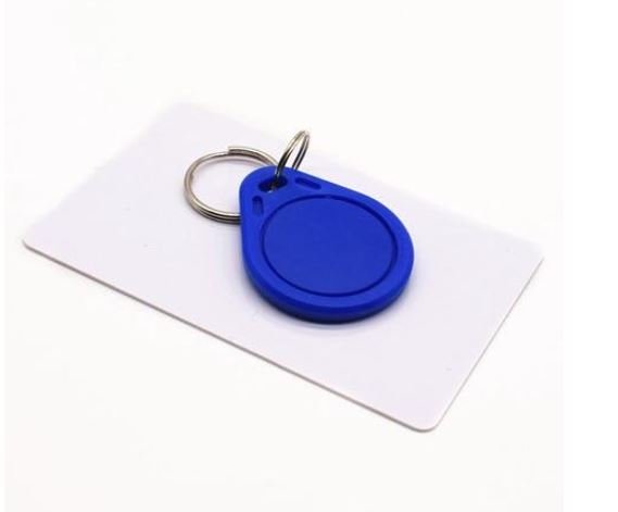
- 125 kHz tags or cards (should be EM4100 compatible)
- Connecting Wires
Point to Note: The connection diagram and the Arduino code will work for both RDM6300 and RDM630 modules as they have similar pin configurations and work on the same frequency. We will use RDM6300 for our project.
Assemble the devices as shown in the schematic diagram below:
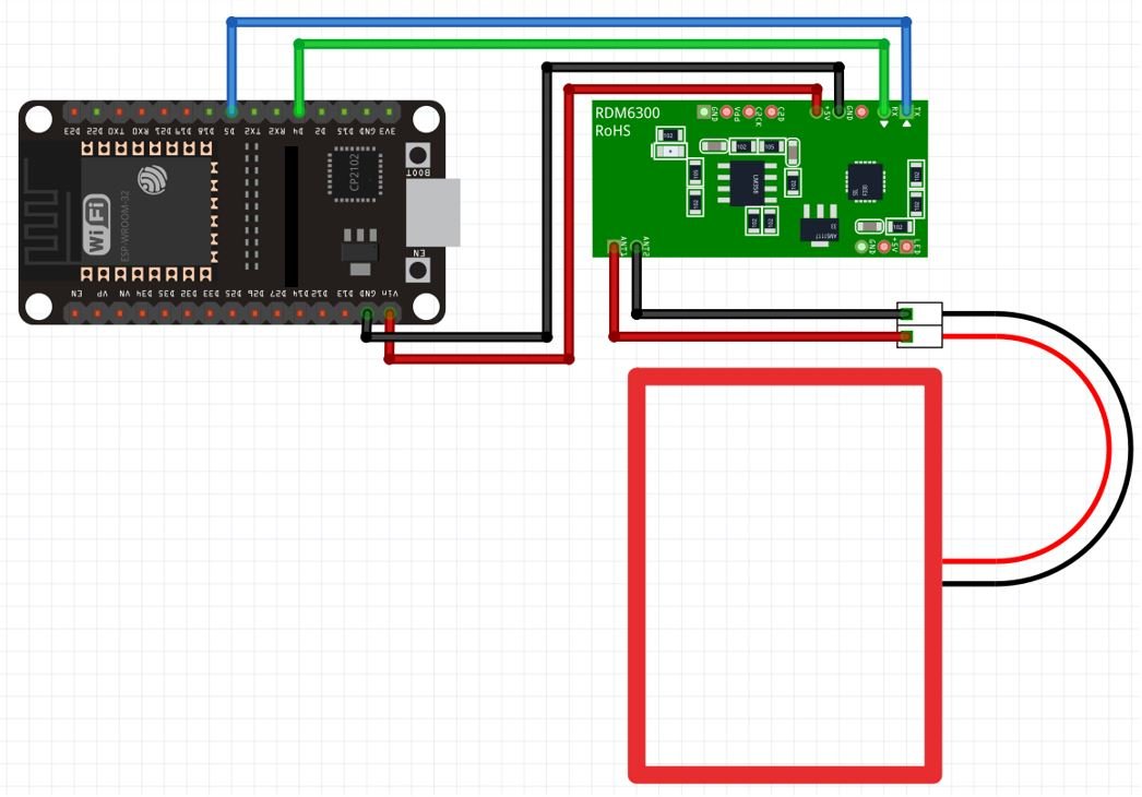
We will connect 4 pins of the RDM6300 module with ESP32. These include the VCC, GND, TX, and RX pins present on Header 1. The VCC will be connected with Vin pin from the ESP32. GND of both the devices will be in common. We will connect the TX pin with GPIO5 and RX pin with GPIO4 of the ESP32 board. The antenna already comes attached to pins ANT1 and ANT2.
Arduino Sketch: RDM6300/RDM630 reading RFID tags/cards
Open your Arduino IDE and go to File > New. A new file will open. Copy the code given below in that file and save it.
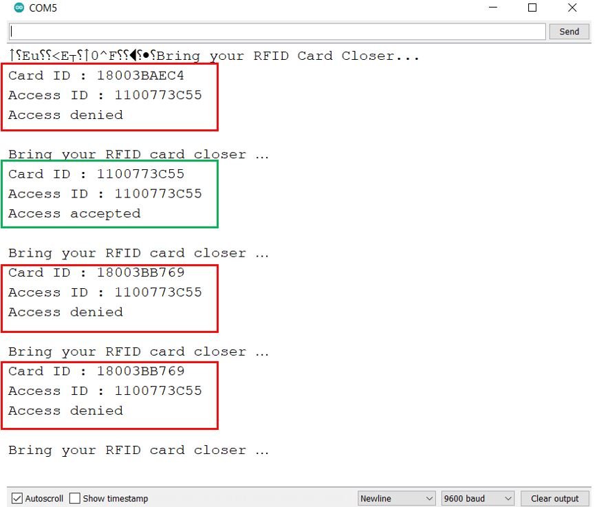
When the user brings a RFID tag/card near RDM6300, it detects the tag and reads its value. If the value is same as defined in the code then ‘Access accepted’ message is shown in the serial monitor. Otherwise ‘Access denied’ message is shown instead. This process occurs every time the user brings the RFID tag closer to the module.
#include <SoftwareSerial.h>
SoftwareSerial RFID(5,4); // RX and TX

String text;
String CardNumber;

void setup()
{
  Serial.begin(9600);
  RFID.begin(9600);
  Serial.println("Bring your RFID Card Closer...");
  CardNumber = "1100773C55";
}
char c;

void loop()
{
  while (RFID.available() > 0) {
    delay(5);
    c = RFID.read();
    text += c;
  }
  if (text.length() > 20)
  check();
  text = "";
}

void check()
{
  text = text.substring(1, 11);
  Serial.println("Card ID : " + text);
  Serial.println("Access ID : " + CardNumber);

  if (CardNumber.indexOf(text) >= 0) {
    Serial.println("Access accepted");
  }
  else {
    Serial.println("Access denied");
  }
  delay(2000);
  Serial.println(" ");
  Serial.println("Bring your RFID card closer …");
}
We will use software serial to communicate between the two devices.
#include <SoftwareSerial.h>Then we will set up the RX and TX pins. These will be passed as a parameter inside the SoftwareSerial().
SoftwareSerial RFID(5,4); // RX and TXTo detect an RFID tag, the RFID.read() function is used which saves the tag/card ID in the string variable ‘text.’
c = RFID.read();
 text += c;
The user defined check() function is used to determine whether the card being read has the same ID as the one which we have defined in the program sketch or not. The serial monitor will display Access accepted/ Access denied message after each RFID tag/card is read.
void check()
{
  text = text.substring(1, 11);
  Serial.println("Card ID : " + text);
  Serial.println("Access ID : " + CardNumber);

  if (CardNumber.indexOf(text) >= 0) {
    Serial.println("Access accepted");
  }
  else {
    Serial.println("Access denied");
  }
  delay(2000);
  Serial.println(" ");
  Serial.println("Bring your RFID card closer …");
}
Demonstration
To see the demonstration of the above code, upload the code to ESP32 board.
Before uploading code, make sure to select ESP32 Dev Module from Tools > Board and also select the correct COM port to which the board is connected from Tools > Port.

Once the code is uploaded to the microcontroller, open the serial monitor and set the baud rate to 9600. Press the ENABLE button on the ESP32 board.

Bring the RFID tag or card close to the antenna. The serial monitor will display the information regarding it. Here you will be able to view the special ID of the tag. Here we have set the tag ID as 1100773C55 in our program sketch. Hence if that particular tag is brought close to RDM6300 then access will be granted otherwise access will be denied. You can see that in the case where other cards have been not allowed. This particular program can be further modified to create a door lock system.
Watch the video demonstration below:
You may like to read:
HOLAAAAAAA MIRA ESTOY PROBANDO TU PRIYECTO SIN EMABRGO NO ME TRANSMITE NADA EL LECTOR RDM630, NO SE SI TENGA QUE HACER ALGUNA CONFIGURACION A LA TARJETASS QUE ESTOY UTILIZANDO, PORBE SI SRIVE EL SERIAL QUE ETA CONECTADO AL MODULO Y FUNCIONA LO QUE HICE FUE MANDAR DATOS DESDE EL SERIAL AL SERIAL DEL RFID Y LLEGAN DATOS ES DECIR QEU LA CONFIGURACION DE PINES Y LA CONEXION CON EL MICRO ESTA BIEN SIN EMABRGO NO SE QUE PASO CUANDO CONECTO EL MODULO DEL PIN G5 A TX DEL MODULO PUES CUADNO ACERCO UNA TARJETA LA ESP32 NO RECIBE DATOS AL PUESTO SERIAL VIRTUAL