PN532 is a simple NFC RFID Arduino based module. This module is a little different from the other RFIC modules and devices because of its functionality. PN532 functions describe modern communication functions through an NFC chip. The single module comes with three communication methods, UART, SPI, and I2C. Most commonly the device interfaces with the Arduino because of its official libraries in Arduino IDE. The module uses to perform multiple functions like data sending, as RFIC cards and an RFID reader. The device can work up to 5-7cm at a close range only, however, due to its less power consumption and fast speed, most of the mobile companies start integrating this module in their devices for multiple functions.
PN532 RFID Module Pinout Configuration
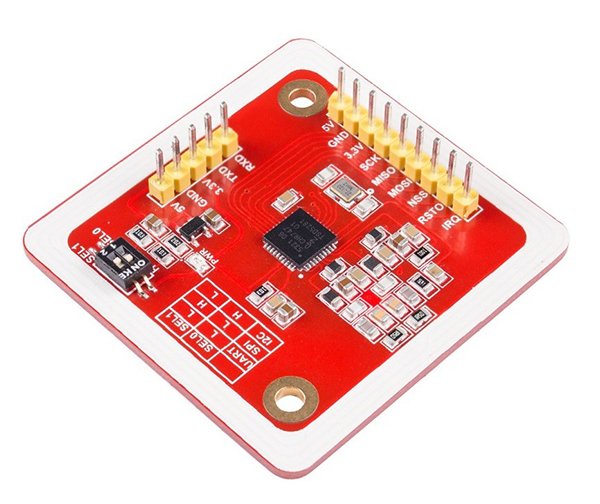
PN532 offers multiple communication methods. So, its number of pins is a little high from other RFID but in the circuit, only some pins are useable at a time. The pin diagram shows all these pins:

Pinout Diagram Details
| Pins | Details |
|---|---|
| VCC | VCC is to power up the whole device. |
| GND | GND pin helps to make the common ground with power supply and the Arduino/Microcontroller. |
| UART Communication Pins | |
| TXD | UART communication requires two communication pins one for transmitting data and second for receiving it. TXD helps to transmit the data. |
| RXD | The RXD pin is the data receiving pin of the UART communication. |
| I2C Communication Pins | |
| SDA | I2C communication requires one pin for data transmission and receiving. Therefore, in the PN532 module SDA is a data pin for I2C communication. |
| SCL | SCL is the clock pin of I2C communication. Data travel between devices according to the clock pulse. |
| IRQ | IRQ pin is an interrupt pin, which helps to I2C communication to generate the interrupt to get the attention of the Arduino/Microcontroller. |
| RST | RST is a reset pin, which helps to reset the device through an external signal. In PN532 this device is for I2C communication. |
| SPI Communication Pins | |
| MOSI | SPI communication requires 4-pins for data communication. Therefore, MOSI is a Master Out Slave In pin, it helps to transmit data from Arduino to PN532. |
| MISO | MISO is a Master In Slave Out, it helps to transmit data from PN532 to Arduino. |
| SS | SS is a slave select pin; it activates the SPI communication of the Slave (PN532). |
| SCK | It’s a clock pin, helps in Transreceiving of data according to the clock pulse. |
PN532 NFC RFID Module Features
The device may be smaller in size but the features list of this device is much different and according to the modern applications. The features PN532 offers are mostly available in specific devices only and increasing daily due to their market demands.
- The PN532 allows the two modules to exchange any kind of data between each other at a specific distance.
- The RFID module uses 13.56MHz frequency and it is legal to use due to its small range.
- The module PN532 is useable as an NTAG/RFID Card Tag and reader.
- The device can operate with 3.3V for SPI and 5V for other communications.
- Onboard, switch helps to change the communication protocol.
- There are three kinds of protocols in a single chip to make an interface with it.
- The device has an onboard antenna and its size is smaller which helps to attach it anywhere in the device without covering too much space.
- This supports the NFC of Android phones.
PN532 Applications
- In mobiles, phone PN532 helps to exchange the data.
- Security keys like cars, doors, etc are using the RFID module in a wide range.
- In most of the shopping malls, PN532 helps to identify the package.
- In most of the Airports, PN532 helps to identify the luggage, bags, etc.
How to use a PN532 RFID Module
The most common and official recommendation for PN532 is to use it with Arduino broads. There’s a lot of work has and research on this module in Arduino. to use it with Arduino first to understand where the module should connect with Arduino. If you are a beginner with Arduino, read this complete guide:
The module uses SPI, I2C and UART protocol. First, connect it with the external module on the following pins:
Arduino UNO
- SPI
- SS – D10
- MOSI – D11
- MISO – D12
- SCK – D13
- I2C
- SCL – A5, D19
- SDA – A4, D18
- UART
- RX – D0
- TX – D1
The other Arduino board’s communication pins are different and available on its official site. Here everything will be according to the Arduino UNO. After connecting all communication pins with the PN532, it also has a toggle switch. The toggle switch pattern activates the single protocol at a time.
| SWITCH 1 | SWITCH 2 | PROTOCOL |
|---|---|---|
| 0 | 0 | UART |
| 1 | 1 | SPI |
| 1 | 0 | I2C |
How to interface PN532 with Arduino
These all the instructions and detail discussed are for the hardware side. To make the PN532 fully operate use the following Arduino programming. You may like to go through:
Programming with Arduino
In programming, the Arduino always depends on the library of PN532. The library offers the developers to change the pins according to the board.
#include <Adafruit_PN532.h>
Protocol
Using the PN532 library, the Arduino won’t be able to communicate. To use the I2C and SPI protocol the following library will help the device to communicate.
#include <Wire.h>
#include <SPI.h>
The wire library is for I2C communication. Both protocols have fixed pins in almost every board. To define the use of any protocol instead of Hardware serial the following object will help:
Adafruit_PN532 nfc(PN532_SS);

Adafruit_PN532 nfc(PN532_IRQ, PN532_RESET);
In case of using the default, SPI pins use the PN532_SS as it is but for I2C protocol replace the PN532_IRQ and PN532_RESET with their digital PINs. Sometimes the boards can cause the problem in communication. So, to avoid the issue in SPI communication the following function helps to define the pins.
Adafruit_PN532 nfc(PN532_SCK, PN532_MISO, PN532_MOSI, PN532_SS);
PN532_SCK, PN532_MISO, PN532_MOSI, and PN532_SS defines the sequence of pins numbers and should be replaced by their new PINs. These all the above discussion is about the choice of the protocol through the library but instructions for activation and use of the PN532 are the same for all the protocols.
Data Communication Initialization
In PN532 the first and most important thing of the programming is to initialize the PN532, without initializing it sometimes the IDE won’t give any error. Then it becomes hard for developers to identify the reason why the module is not working.
nfc.begin(); // For initilizing the PN532
nfc.SAMConfig(); // It will set the card in reader mode
The communication method and all the protocols are for only initializing the module. To transmit and receive data everything should be initialized within the programming. There are multiple different methods that the NFC module can perform.
NFC RFID Example with Arduino
Her we will define the PN532 as a reader for NTAGS. Every NTAGS card has a code that is viewable and changeable with PN532. To do that programming will be required for different functions. First, attach the pins of a module with Arduino at I2C pins that are D18 and D19. After that, upload the following code.

Arduino Code with Libraries
#include <Wire.h>
#include <Adafruit_PN532.h>
#define PN532_IRQ (2)
#define PN532_RESET (3)
Adafruit_PN532 nfc(PN532_IRQ, PN532_RESET);
void setup(void) {
Serial.begin(115200);
nfc.begin();
uint32_t versiondata = nfc.getFirmwareVersion();
if (! versiondata) {
Serial.print("Didn't find PN53x board");
while (1);
}
nfc.SAMConfig();
}

void loop(void) {
uint8_t success;
uint8_t uid[] = { 0, 0, 0, 0, 0, 0, 0 };
uint8_t uidLength;
success = nfc.readPassiveTargetID(PN532_MIFARE_ISO14443A, uid, &uidLength);
if (success) {
Serial.println("Found an ISO14443A card");
Serial.print(" UID Length: "); Serial.print(uidLength, DEC); Serial.println(" bytes");
Serial.print(" UID Value: ");
nfc.PrintHex(uid, uidLength);
Serial.println("");
if (uidLength == 7){
uint8_t data[32];
Serial.println("Seems to be an NTAG2xx tag (7 byte UID)");
for (uint8_t i = 0; i < 42; i++){
success = nfc.ntag2xx_ReadPage(i, data);
Serial.print("PAGE ");
if (i < 10){
Serial.print("0");
Serial.print(i);
}
else{
Serial.print(i);
}
Serial.print(": ");
if (success){
nfc.PrintHexChar(data, 4);
}
else{
Serial.println("Unable to read the requested page!");
}}}
else
{
Serial.println("This doesn't seem to be an NTAG203 tag (UUID length != 7 bytes)!");
}
Serial.println("\n\nSend a character to scan another tag!");
Serial.flush();
while (!Serial.available());
while (Serial.available()) {
Serial.read();
}
Serial.flush();
}
}
After uploading the code, now place the card near the module. The serial monitor will be able to show the card codes. The NTAGS cards are usable for any industry for security purposes. The above code will only help to read the card code but the cards are programmable by PN532 with different programming. The security of NTAGS is a little different in every version. Every module has different bits for security but all of them are usable with PN532. The most NTAGS works with NTAG203, NTAG213, NTAG215, and NTAG2016.
2D Diagram

Alternative Wireless Options :
Does the board also work with arduino nano 33 ble?