In this tutorial, you will learn to interface oa servo motor with the PIC16F877A microcontroller. This tutorial covers the programming required to control the servo motor, as well as the hardware connections between the servo motor and the PIC16F877A microcontroller. Let’s start with a basic introduction to the servo motor. Then, I will move forward with its circuit diagram and programming.
Recommended Components
The following components are used in this project or are helpful for building it with a PIC microcontroller.
| Component | How it’s used in this project | Buy on Amazon |
|---|---|---|
| PIC16F877A microcontroller | Generates the timed control pulses that set the servo angle. | Check Price |
| PICkit 5 programmer/debugger | Uploads the servo control program to the PIC16F877A. | Check Price |
| Servo motor (SG90) | The 180° servo whose shaft position is driven by the PIC pulses. | Check Price |
| Breadboard | Provides a base for wiring the PIC to the servo and power. | Check Price |
| Jumper Wires | Links the RB0 signal, 5V, and GND lines to the servo. | Check Price |
As an Amazon Associate we earn from qualifying purchases. Prices and availability are accurate as of the date/time indicated and are subject to change.
What is a Servo Motor?
A servo motor is a unique type of motor that executes actions according to specific instructions. What sets it apart is its exceptional angular precision. Unlike typical electric motors that continuously rotate until power is applied or removed, a servo motor rotates precisely to a designated degree or until directed otherwise. After reaching the designated position, the motor ceases its movement and remains idle until a new instruction is provided for subsequent actions.
Servo motors are governed by a servomechanism, a system that manages their operation. The motor’s angular rotation and final position are guided by feedback mechanisms. The control line’s input determines the desired position for the output shaft. This intricate interplay between input, feedback, and control ensures that servo motors respond with remarkable accuracy to specific positional requirements.
servo motor?
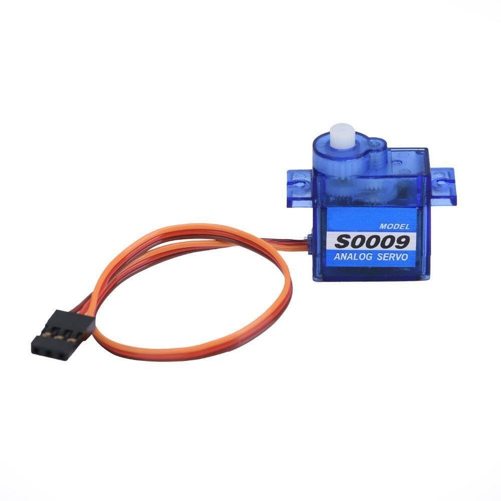
SG-90 Servo Motor Introduction
SG90 is a low-cost and high-output power servo motor. It can rotate up to 180 degrees and each step can be of maximum 90 degrees. Moreover, it is small enough that it can easily fit into your robotics ARM or obstacle avoidance robotics projects. On top of that, it requires only one output pulse signal to control its movement.
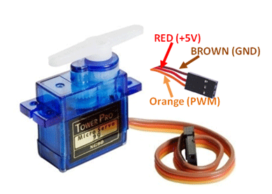
Pinout
The following figure shows the pinout diagram of the SG90 servo motor. It consists of three pins only such as PWM, ground, and Vcc pin. Brown, orange and red wires are GND, Vcc, and PWM pins respectively. Details and functionality of each pin are listed in the next section.
Pin Configuration Details
VCC and ground, as their names suggest, are the power supply pins used to power the servo motor. Only a 5-volt power signal is required to power this motor. Most microcontrollers or development boards have an onboard 5-volt supply that we can use to power SG90 servos.
PWM Pin is an input pin of a servo motor. We provide a PWM output signal from the pic microcontroller to drive the servo motor through this pin.
This table briefly described all three pins:
| Wire of motor | Possible colors of each wire |
|---|---|
| Vcc pin | Red |
| GND pin | Black, or brown |
| Control Signal / PWM pin | Yellow, orange, or white |
How to control Servo motor rotator movement?
The position of the servo rotator is directly related to the width of the pulse applied to the PWM signal of the motor.
To control rotation, we apply pulses to the PWM pin of the servo motor. The frequency of the PWM signal should be 50Hz, which means the control signal pulse should be applied to the PWM pin every 20ms. The width of the pulse has a direct relation with the angular position of the motor.
For SG90-type servo motors, a pulse width of 1 ms corresponds to a 0-degree rotation, 1.5 ms corresponds to a 90-degree rotation, and 2 ms corresponds to a 180-degree rotation.
Hence, the pulse width between 1ms to 2ms controls the shaft position of the servo motor between 0 to 180 degrees.
Note: This pulse duration may be different for different types of servo motors.
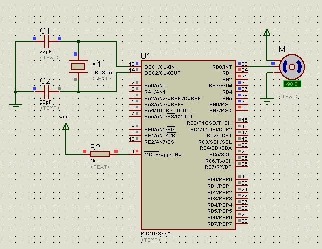
Circuit Diagram for Servo Motor Interfacing with PIC16F877A Microcontroller
The circuit diagram provided illustrates the interfacing of a servo motor with a PIC16F877A microcontroller. Let’s break down the components and connections shown in the diagram:
- The servo motor is depicted as a labeled rectangular box named “Servo Motor” in the upper section of the diagram.
- The control wire of the servo motor is physically connected to the RB0 (Port B, Pin 0) pin of the PIC16F877A microcontroller. This specific pin functions as an output channel, providing the necessary signals to achieve angular displacement in the motor.
- The VCC (power supply) and GND (ground) pins of the servo motor are directly linked to the corresponding VCC and GND pins of the microcontroller. This connection guarantees that the servo motor is adequately powered for proper operation.
- Solid lines represent the connections established between the microcontroller and the servo motor components.
- A power symbol (+) represents connections to the VCC pins, while a ground symbol (-) represents connections to the GND pins.
Overall, the circuit diagram illustrates a straightforward interaction between the PIC16F877A microcontroller and the servo motor. By connecting the control wire of the servo motor to the RB0 pin of the microcontroller, precise angular displacement can be achieved by adjusting the length of the applied pulse, thus enabling accurate motor control.
The circuit diagram for this setup is straightforward. The control wire of the servo motor is directly linked to the RB0 pin of the microcontroller. This specific pin is responsible for delivering the necessary angular displacement to the motor. In this project, our focus is on a servo motor designed for an angular range of 0° to 180°. Within this defined scope, we achieve precise control over the motor’s rotation by manipulating the width of the pulses, ensuring that the desired angle is attained with accuracy.
Pic Microcontroller MikroC Code
The following code is written using MikroC for PIC compiler. But if you don’t know how to use MikroC for PIC compiler, you can check the following tutorials:
- How to Use “MikroC PRO for PIC” to Program PIC Microcontrollers
- Pic microcontroller programming in c using Mikroc Pro for PIC
The provided code is for controlling a servo motor’s rotation at three different angles (0°, 90°, and 180°) using a PIC16F877A microcontroller.
void Rotation0() //0 Degree
{
unsigned int i;
for(i=0;i<50;i++)
{
PORTB.F0 = 1;
Delay_us(800); // pulse of 800us
PORTB.F0 = 0;
Delay_us(19200);
}
}

void Rotation90() //90 Degree
{
unsigned int i;
for(i=0;i<50;i++)
{
PORTB.F0 = 1;
Delay_us(1500); // pulse of 1500us
PORTB.F0 = 0;
Delay_us(18500);
}
}

void Rotation180() //180 Degree

{
unsigned int i;
for(i=0;i<50;i++)
{
PORTB.F0 = 1;
Delay_us(2200); // pulse of 2200us
PORTB.F0 = 0;
Delay_us(17800);
}
}

void main()
{
TRISB = 0; // PORTB as Ouput Port
do
{
Rotation0(); //0 Degree
Delay_ms(2000);
Rotation90(); //90 Degree
Delay_ms(2000);
Rotation180(); //180 Degree
}while(1);
}
Individual functions for angular rotation of the motor by 0°, 90°, and 180° have been defined at the beginning of the code. However, there are a few clarifications and corrections to be made in the explanation:
In this tutorial, we are not using the actual Pulse Width Modulation (PWM) feature of the PIC16F877A microcontroller to generate pulses. Instead, the pulses are simulated using delays within the program. Each delay duration for a specific angle corresponds to the pulse length required for the motor to rotate to the respective angle.
- For instance, for the 0° angle, the pulse width is approximately 800 microseconds (us), so a delay of 800 microseconds is implemented while the PORT pin RB0 is set to high. This high signal initiates the pulse.
- Similarly, for a rotation of 90°, a pulse of approximately 1500 microseconds is needed. Therefore, a delay of 1500 microseconds is applied while PORT pin RB0 is high.
- For a full rotation of 180°, a pulse of around 2200 microseconds is necessary. Hence, a delay of 2200 microseconds is used with PORT pin RB0 in its high state.
In summary, the program mimics the effect of Pulse Width Modulation by utilizing timed delays. The duration of each delay corresponds to the required pulse length for the servo motor to rotate to the specified angle. This approach, while not employing true hardware PWM, achieves the desired rotation angles effectively.
Furthermore, it’s important to point out that while this method works, it may not offer the precision and accuracy of hardware PWM in more demanding applications. Also, the exact pulse durations might need adjustments based on the servo motor’s specifications and characteristics.
Applications
Servo motor has a large number of application in industries. In industrial manufacturing, the conveyor belt uses servo motors to control the precise movement of the belt. Servo motors are most popular in robotics. The precise angular displacement of a robot’s arm is controlled by a servo motor. The physical movement of the solar panel with respect to the sun is also carried out by servo motors in a solar tracking system.
// your codes are straight understandable….. have a long life
can i use this code to run the motor using L293D
thank you so much, it’s really useful
sir why r u using a loop of 50 also the pulse that are generated on oscilloscope on proteus are of different time and servo is not going to 90 instead it is going to -33 in my case im using pic18f4520 i have made the changes accordingly to the code for pic 18
i need to be assited to write a code of running 5 servo motors using c language and MPLAB compiler.
Where to buy servomotor with pIc 16f877a can install with one half square meter solar panel
you can buy from amazon and aliexpress
How mich the servo motor with pic16f877a can caŕry solar panel about 2kls
Please i want to control the speed of rotation of the servo motor so that it can get the right angle slower.
If any one could help me !
unsigned int rpm;
unsigned int speed;
unsigned int pulse=0;
float *x;
char ms,sec,minu,hr;
int timer;
char text[15];
void main()
{
TRISD.F0=1;
TRISA=0X00;
PORTA=0;
TRISC=0X00;
PORTC=0;
rpm=0;
speed=0;
#define sw PORTD.RD0//RD0 PIN pulse input
TRISB=0; // COnfigurePortB as output Port.
LATB=0x01; // Turn on LED on PORT B pin0
T0CON=0x07; // Prescaler= 1:256, 16-bit mode, Internal Clock
while(1)
{
if(sw==1){
while(sw==1);
pulse++ ;
speed=1000*pulse++/1;
}
if(pulse>=721)pulse=0;
if(RD0_bit==1)pulse++;
if(pulse==pulse=129 && pulse<=180 ){
PORTA.F2=1;
}
// Values calculated for 1 second delay with 20MHz crystal
TMR0H=0xB3; // Placing Lower byte in TMR0L
TMR0L=0xB4; // Placing Lower byte in TMR0L
T0CON.TMR0ON=1; // Timer0 On
while(INTCON.TMR0IF==0); // Wait until TMR0IF gets flagged
T0CON.TMR0ON=0; // Timer0 Off
INTCON.TMR0IF=0; // Clear Timer0 interrupt flag
LATB=(LATB<>7); // Circular right shift at PortB
}
}
please help me to make real velocity and rpm
C’est possible de commander le servo moteur SUR 45°?