In this tutorial, we will learn how to perform wireless HTTP communication between two ESP32 boards using Wi-Fi without any physical router or internet connection. In other words, we will learn to exchange data between ESP32 boards wirelessly. The type of communication will be HTTP where one ESP32 board acts as an HTTP client generating an HTTP request and the other as a server that responds to the HTTP requests.
We will connect a BME280 sensor with an ESP32 server that will transfer sensor data to the ESP32 client. Any appropriate sensor can be used such as DS18B20, DHT22, LM35, and MPU6050 but for this project, we will use a BME280 sensor which is used to measure temperature, pressure, and humidity.
This article is divided into the following sections:
- Project Overview
- Prerequisites (Installing Libraries)
- Setting ESP32 as server AP mode (Schematic, Arduino Sketch and demonstration)
- Setting ESP32 as client station mode (Schematic, Arduino Sketch and demonstration)
- Conclusion
Recommended Components
The following components are used in this project or are helpful for building it with the ESP32.
| Component | How it’s used in this project | Buy on Amazon |
|---|---|---|
| ESP32 Development Board (DevKit V1) | Two of these run the server and client sketches that communicate over Wi-Fi in this project. | Check Price |
| Micro USB Cable | Connects each ESP32 to your computer for flashing the code and powering the boards. | Check Price |
| Breadboard | Holds the ESP32 boards while you set up and test the Wi-Fi communication. | Check Price |
| Jumper Wires | Handy for any supporting connections while prototyping the setup. | Check Price |
As an Amazon Associate we earn from qualifying purchases. Prices and availability are accurate as of the date/time indicated and are subject to change.
Project Overview
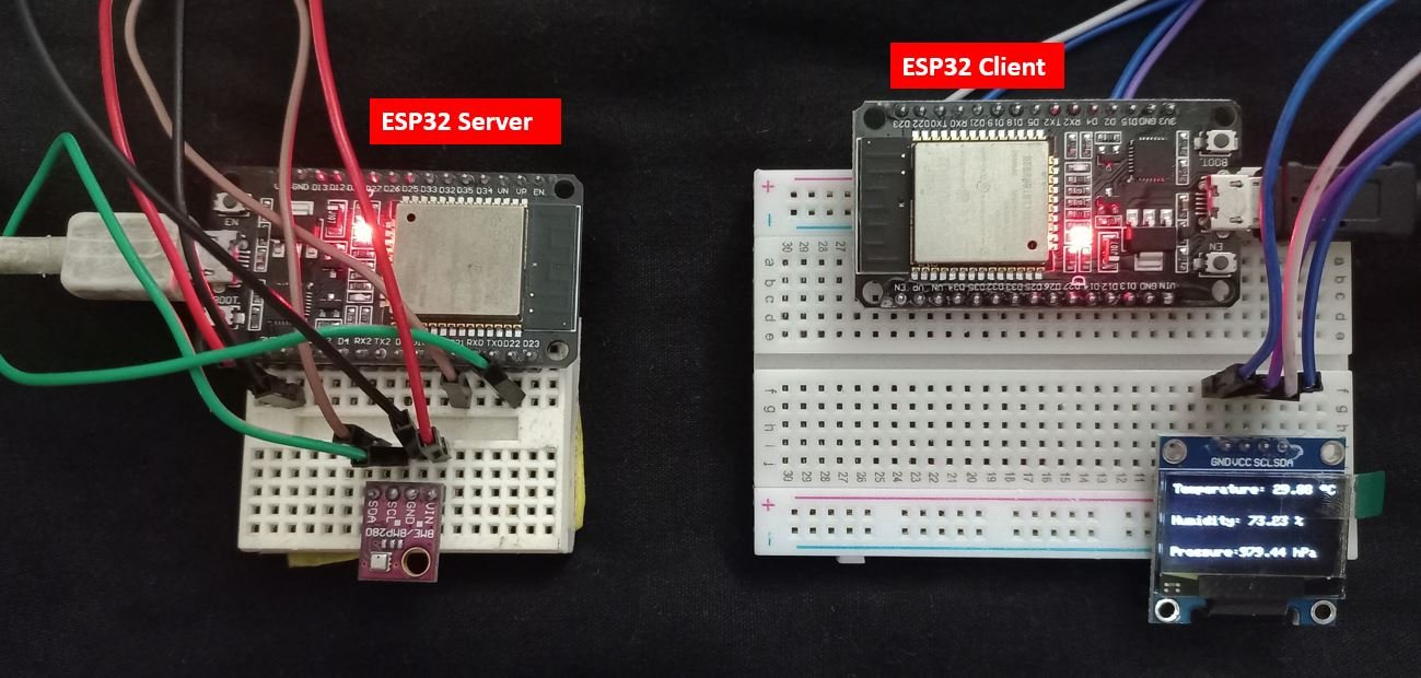
The ESP32 server will be connected with a BME280 sensor whereas the ESP32 client will be connected with a 0.96 inch OLED display.
Our aim is to send sensor readings from ESP32 server to ESP32 client via HTTP requests without the use of a physical router. To do that we will follow the steps given below:
- The ESP32 server will be in Soft Access Point mode. In the Soft AP mode, the ESP32 server will create its own wireless Wi-Fi network similar to our existing Wi-Fi router. In this mode, we do not need to connect ESP32 to a physical router.
- The ESP32 client will be in station mode and thus will be able to connect to the ESP32 server’s network.
- Now the ESP32 client will request sensor readings from the ESP32 server via HTTP communication. These requests will be made on the IP address of the ESP32 server. In our case the ESP32 client will request on the following route: IP_ADDRESS/temperature, IP_ADDRESS/pressure and IP_ADDRESS /humidity.
- The ESP32 server will receive the HTTP requests and will respond by sending the readings to the ESP32 client.
- These readings will be displayed on the OLED screen when the ESP32 client will receive them.
Prerequisites
Before we start this project make sure you are familiar with and have the latest version of Arduino IDE installed and also have ESP32 add-on installed in Arduino IDE:
Install ESP32 add-on in Arduino IDE
Installing BME280 Libraries
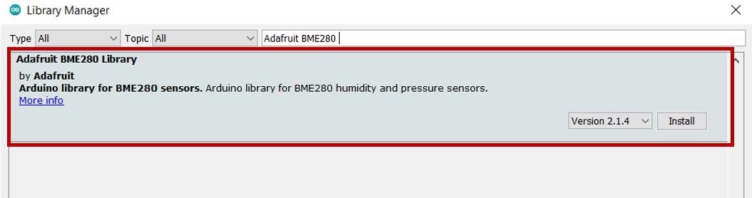
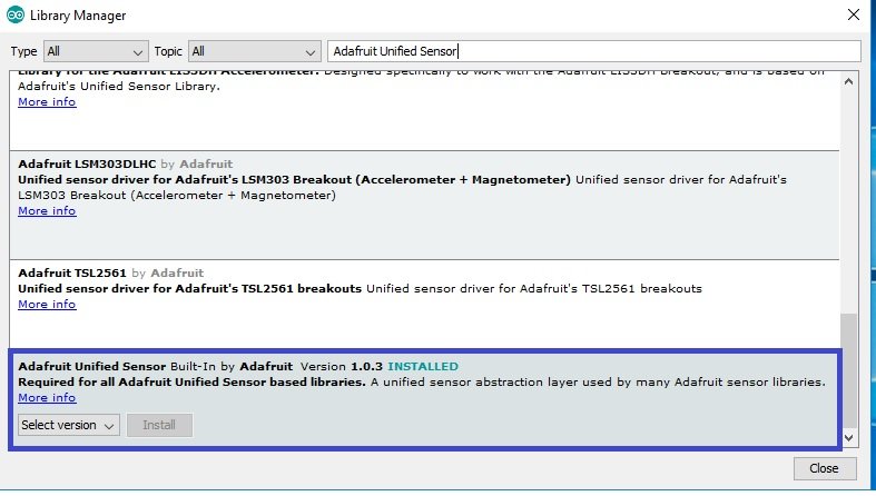
As we are connecting the BME280 sensor with ESP32 server so we will have to install BME280 libraries. We will require two libraries for this project:
- Adafruit_BME280 library
- Adafruit_Sensor library
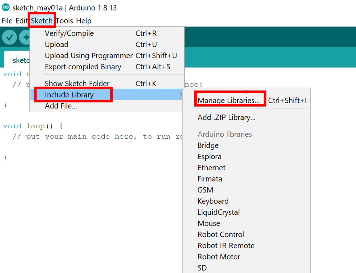
We will use the Library Manager in our Arduino IDE to install the latest versions of the libraries. Open your Arduino IDE and go to Sketch > Include Libraries > Manage Libraries. Type each library name in the search bar and install them both.
Installing OLED Library
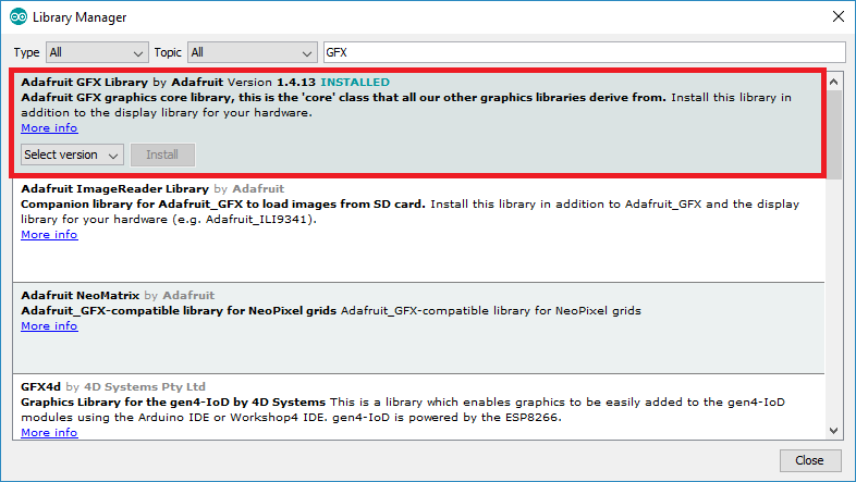
To use the OLED display in our project, we have to install the Adafruit SSD 1306 library and Adafruit GFX library in Arduino IDE. Follow the steps below to successfully install them.
Open Arduino IDE and click on Sketch > Library > Manage Libraries
The following window will open up.

Type ‘SSD1306’ in the search tab and install the Adafruit SSD1306 OLED library.

We will also require the Adafruit GFX library which is a dependency for SSD1306. Type ‘Adafruit GFX’ in the search tab and install it as well.
Installing ESPAsyncWebServer Library and Async TCP Library
To handle the HTTP requests we will require the following libraries:
- ESPAsyncWebServer library
- AsyncTCP library
Both of these libraries are not available in the Arduino library manager. Therefore, we will have to download and load them on our ESP32 board ourselves.
- To install the ESPAsyncWebServer library for free, click here to download. You will download the library as a .zip folder which you will extract and rename as ‘ESPAsyncWebServer.’ Then, transfer this folder to the installation library folder in your Arduino IDE.
- To install the Async TCP library for free, click here to download. You will download the library as a .zip folder which you will extract and rename as ‘AsyncTCP.’ Then, transfer this folder to the installation library folder in your Arduino IDE.
Likewise, you can also go to Sketch > Include Library > Add .zip Library inside the IDE to add the libraries as well.
After installing the libraries, restart your IDE.
Setting ESP32 server (Access Point mode)
We will first set up the ESP32 server that will be in AP mode. As you already know we will connect it with a BME280 sensor. The BME280 sensor is used to measure readings regarding ambient temperature, barometric pressure, and relative humidity. It is mostly used in web and mobile applications where low power consumption is key. This sensor uses I2C or SPI to communicate data with the micro-controllers. Although there are several different versions of BME280 available in the market, the one we will be studying uses the I2C communication protocol and SPI.
Our ESP32 server will receive HTTP requests on its IP address/temperature, /pressure and /humidity from the client side. To respond to these requests, the server will send the respective sensor data to the client via HTTP communication.
Recommended Reading: ESP32 soft access point web server in Arduino IDE
Connecting BME280 sensor with the ESP32 development board
The connection of BME280 with the ESP32 boards is very easy. We have to connect the VCC terminal with 3.3V, ground with the ground (common ground), SCL of the sensor with SCL of the module, and SDA of the sensor with the SDA pin of the ESP32 module.
The I2C pin in ESP32 for SDA is GPIO21 and for SCL is GPIO22.
Required Components:
We will need the following components to connect our ESP32 server board with the BME280 sensor.
- ESP32 board
- BME280 Sensor
- Connecting Wires
- Breadboard
Follow the schematic diagram below for the ESP32 module and connect them accordingly.
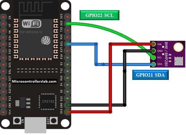
The SCL pin is connected with its respective GPIO pin on the ESP32 board. Likewise, the SDI terminal is connected with its respective GPIO pin on the board. Vin is connected with a 3.3V pin on the module and both the ESP32 board and the sensor is commonly grounded.
You can read this in-depth guide:
BME280 with ESP32 – Display Values on OLED ( Arduino IDE)
Arduino Sketch ESP32 server
Open your Arduino IDE and go to File > New. A new file will open. Copy the code given below in that file and save it. This code sets the ESP32 in soft access point mode. Additionally, it acquires sensor data from the BME280 sensor and listens and responds to HTTP requests by sending current temperature, humidity, or pressure values to the client accordingly.
#include "WiFi.h"
#include "ESPAsyncWebServer.h"
#include <Wire.h>
#include <Adafruit_Sensor.h>
#include <Adafruit_BME280.h>
const char* ssid = "ESP32-Soft-accessPoint";
const char* password = "microcontrollerslab";
Adafruit_BME280 bme;
AsyncWebServer server(80);
String Temperature() {
return String(bme.readTemperature());
}
String Humidity() {
return String(bme.readHumidity());
}
String Pressure() {
return String(bme.readPressure() / 100.0F);
}
void setup(){
Serial.begin(115200);
Serial.println();
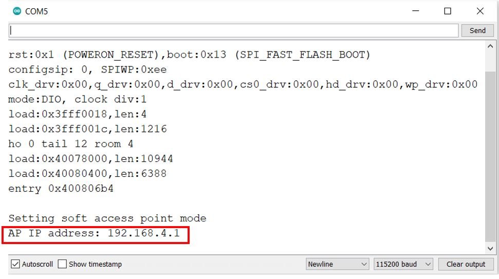
Serial.println("Setting soft access point mode");
WiFi.softAP(ssid, password);
IPAddress IP = WiFi.softAPIP();
Serial.print("AP IP address: ");
Serial.println(IP);
server.on("/temperature", HTTP_GET, [](AsyncWebServerRequest *request){
request->send_P(200, "text/plain", Temperature().c_str());
});
server.on("/humidity", HTTP_GET, [](AsyncWebServerRequest *request){
request->send_P(200, "text/plain", Humidity().c_str());
});
server.on("/pressure", HTTP_GET, [](AsyncWebServerRequest *request){
request->send_P(200, "text/plain", Pressure().c_str());
});
bool status;
status = bme.begin(0x76);
if (!status) {
Serial.println("BME280 not connected properly!");
while (1);
}
server.begin();
}
void loop(){
}
How the Code Works?
Including Libraries
Firstly, we will include the relevant libraries which are necessary for this project. We are using five libraries: WiFi.h, ESPAsyncWebServer.h, Wire.h, Adafruit_BME280.h and Adafruit_Sensor.h.
The WiFi.h and ESPAsyncWebServer.h will be required for the HTTP communication. The Wire.h library will allow us to communicate through the I2C protocol that is required between the ESP32 and the BME280 sensor. The other two libraries are the ones that we previously installed and will be required for the BME280 sensor functionality.
#include "WiFi.h"
#include "ESPAsyncWebServer.h"
#include <Wire.h>
#include <Adafruit_Sensor.h>
#include <Adafruit_BME280.h>
Setting Network Credentials
Next, we need to define the SSID name and the password. Following lines set the name of ssid as “ESP32-Soft-accessPoint” and password as “microcontrollerslab”. You can replace the ssid and password to whatever value you want.
const char* ssid = "ESP32-Soft-accessPoint";
const char* password = "microcontrollerslab";
Creating BME280 Object
Additionally, we will also create an object of Adafruit_BME280 called bme which we will use later on to initialize the BEM280 sensor.
Adafruit_BME280 bme; Creating the AsyncWebServer Object
The AsyncWebServer object will be used to set up the asynchronous web server. We will pass the default HTTP port which is 80, as the input to the constructor. This will be the port where the server will listen to the requests.
AsyncWebServer server(80);Obtaining Temperature, Pressure and Humidity readings
Now we will create three separate functions called Temperature(), Pressure() and Humidity(). Each function will return its respective reading in the form of string through bme.readTemperature(), bme.readHumidity() and bme.readPressure() / 100.0F. These will return the current temperature, pressure and humidity readings from the BME280 sensor.
String Temperature() {
  return String(bme.readTemperature());
}

String Humidity() {
  return String(bme.readHumidity());
}

String Pressure() {
  return String(bme.readPressure() / 100.0F);
}
setup()
Inside the setup() function, we will open a serial connection at a baud rate of 115200.
Serial.begin(115200);The Serial.print() function will print the string “Setting soft access point mode” on the Serial monitor. The WiFi.softAP() function will be used to set the soft AP mode with two arguments as an input to this function. The first is the name of SSID which you want to set and second is the password of Wi-Fi network. These two parameters were already defined earlier.
Serial.print("Setting soft access point mode");
WiFi.softAP(ssid, password);
The WiFi.softAPIP() function will be used to get the IP address of ESP32 server. This line will save the IP address value in the variable ‘IP’. This will then get printed in the serial monitor.
IPAddress IP = WiFi.softAPIP();
Serial.print("AP IP address: ");
Serial.println(IP);
Handling Requests
In this section, we will discuss how our ESP32 server board will handle the requests on the different URLs.
/temperature URL
Firstly, we will deal with the /temperature URL request which the ESP32 server board will receive.
We will use the send_P() method. This method will take in three parameters. The first is 200 which is the HTTP status code for ‘ok’. The second is “text/plain” which will correspond to the content type of the response. The third input is the value returned from the Temperature() function converted to a character. This will be the current temperature reading and will be sent as a response to the ESP32 client.
server.on("/temperature", HTTP_GET, [](AsyncWebServerRequest *request){
    request->send_P(200, "text/plain", Temperature().c_str());
  });
/pressure URL
Secondly, we will deal with the /pressure URL request which the ESP32 server board will receive.
We will use the send_P() method. This method will take in three parameters. The first is 200 which is the HTTP status code for ‘ok’. The second is “text/plain” which will correspond to the content type of the response. The third input is the value returned from the Pressure() function converted to a character. This will be the current pressure reading and will be sent as a response to the ESP32 client.
 server.on("/pressure", HTTP_GET, [](AsyncWebServerRequest *request){
    request->send_P(200, "text/plain", Pressure().c_str());
  });
/humidity URL
Lastly, we will deal with the /humidity URL request which the ESP32 server board will receive.
We will use the send_P() method. This method will take in three parameters. The first is 200 which is the HTTP status code for ‘ok’. The second is “text/plain” which will correspond to the content type of the response. The third input is the value returned from the Humidity() function converted to a character. This will be the current humidity reading and will be sent as a response to the ESP32 client.
 server.on("/humidity", HTTP_GET, [](AsyncWebServerRequest *request){
    request->send_P(200, "text/plain", Humidity().c_str());
  });
Initializing Sensor
The following lines of code will initialize the BME280 sensor. If the connection between the module and the sensor is incorrect, it will print that message on the serial monitor that is “BME280 not connected properly!”. This is inside the setup() function.
bool status;
  status = bme.begin(0x76);
  if (!status) {
    Serial.println("BME280 not connected properly!");
    while (1);
  }
To start the server, we will call begin() on our server object.
server.begin();Testing Arduino Sketch
Let us first test this Arduino sketch on our ESP32 server before setting up the ESP32 client.
Choose the correct board and COM port before uploading your code to the board. Go to Tools > Board and select ESP32 Dev Module.

Next, go to Tools > Port and select the appropriate port through which your board is connected.

Click on the upload button to upload the code into the ESP32 development board. After you have uploaded your code to the development board, press its ENABLE button.

Open your Serial Monitor. If you are able to see the IP address then it means you were successful in setting up your ESP32 server board as an access point.
Testing ESP32 Handling Requests
Now let us test whether our ESP32 board is receiving and responding to HTTP requests or not. First, we will connect any system e.g. smart phone, laptop or computer to the ESP32 server’s wireless network. To do that go to your device’s Wi-Fi option and search for available Wi-Fi networks. You will be able to see the name of SSID that you specified in the Arduino sketch.
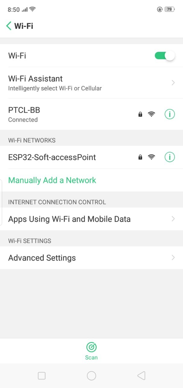
After that click on the Wi-Fi option and enter the password which you set inside the sketch as shown in the picture.
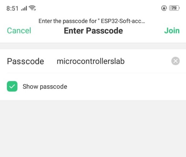
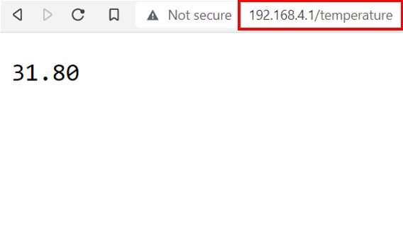
Now click on the join button to connect to this Wi-Fi network. Once you connected with the Wi-Fi of ESP32 server, now go to the web browser of your mobile device. Type your IP_ADDRESS/temperature and press enter. The current temperature reading will get displayed.
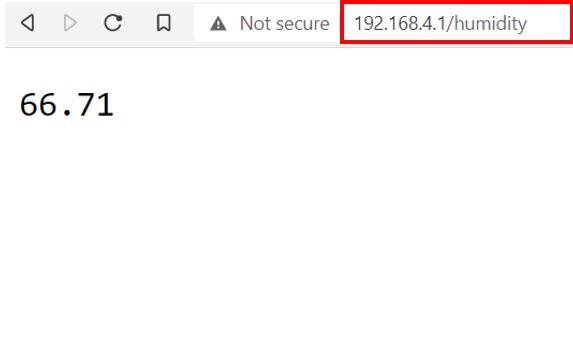
Now type your IP_ADDRESS/humidity and press enter. The current pressure reading will get displayed.
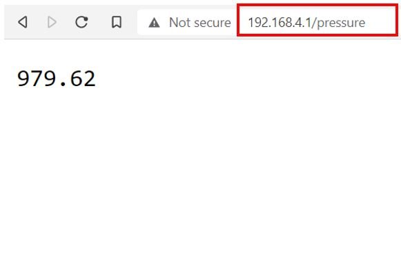
Likewise, type your IP_ADDRESS/pressure and press enter. The current humidity reading will get displayed.
If you are getting valid readings for all three parameters then it means that your ESP32 server is handling the requests promptly. Now let us move ahead and set up the ESP32 client.
Setting ESP32 client (Station mode)
Now we will set up the ESP32 client that will be in station mode. It will connect with the ESP32 server’s wireless network. As you already know we will connect it with an OLED display. Our ESP32 client will make HTTP requests on IP address/temperature, /pressure and /humidity to the server side. To respond to these requests, the server will send the respective sensor data to the client via HTTP communication. This sensor data will get displayed in the OLED screen on the client side.
Connecting SSD1306 OLED Display with ESP32
SSD1306 OLED Pinout
Let us take a look at the OLED display which we will be using in this article. It is called SSD 1306 0.96-inch OLED display which has 128×64 pixels and communicates only via I2C protocol with the ESP development boards. It is cheap and readily available in the market.
Below you can see the pinout of this OLED Display.
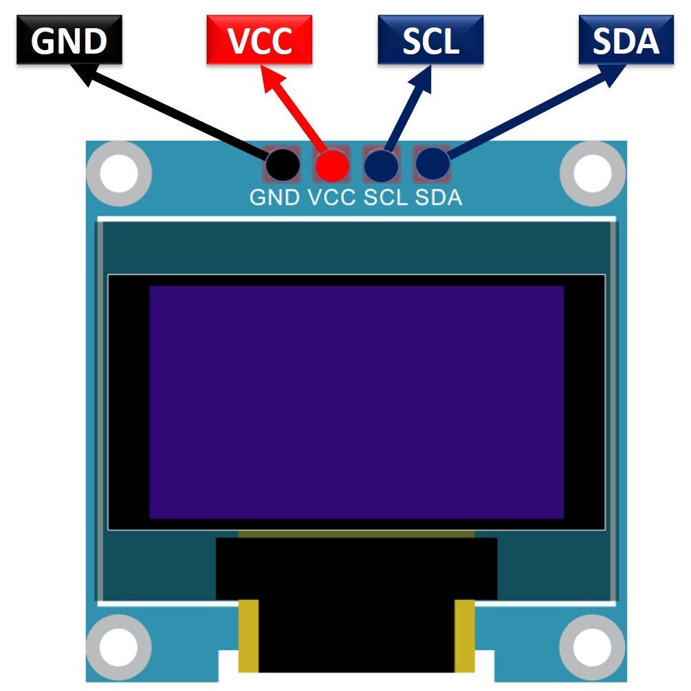
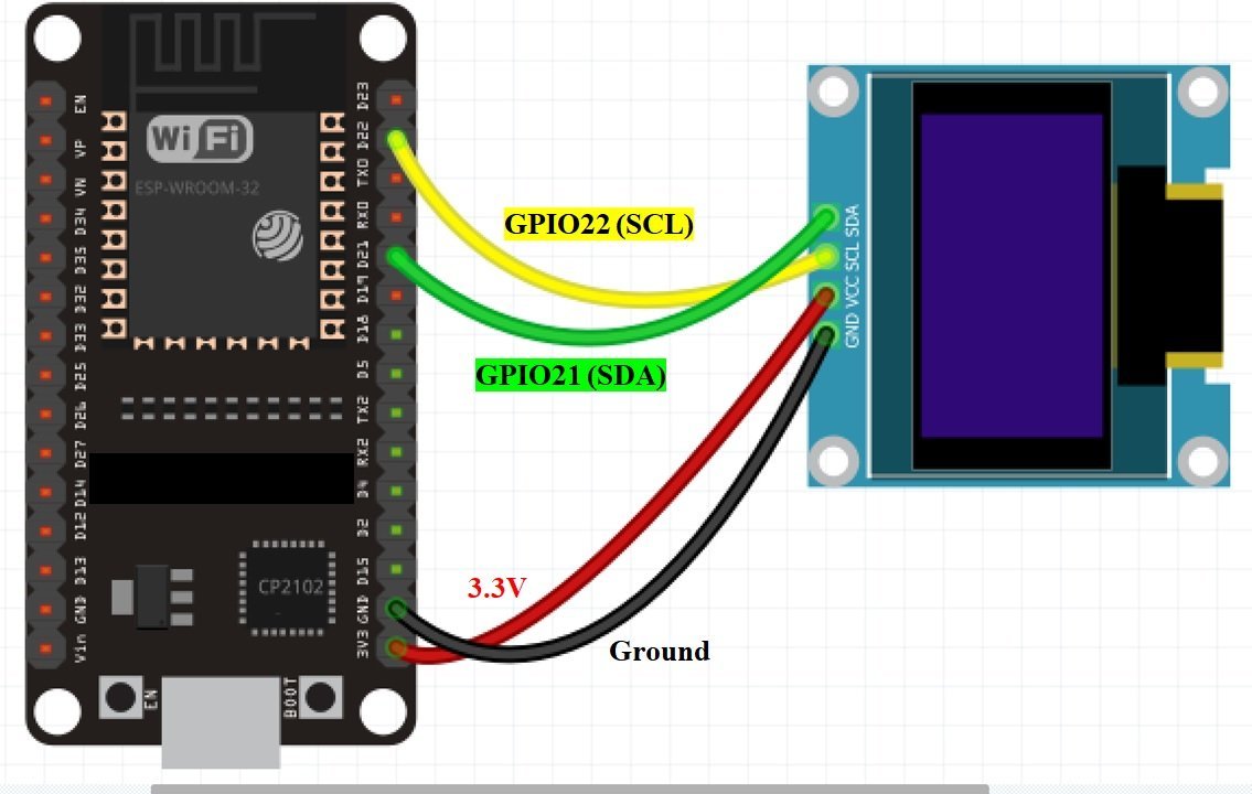
The OLED display has 4 terminals which we will connect with the ESP32 board. As the OLED display requires an operating voltage in the range of 3.3-5V hence we will connect the VCC terminal with 3.3V which will be in common with the ESP32 board. SCL of the display will be connected with the SCL pin of the module and the SDA of the display will be connected with the SDA of the module. By default, the I2C pin in ESP32 for SDA is GPIO21, and for SCL is GPIO22. The connections between the two devices can be seen below.
| ESP32 board | SSD1306 OLED Display |
|---|---|
| VCC=3.3V | VCC |
| GPIO21(I2C SDA) | SDA |
| GPIO22(I2C SCL) | SCL |
| GND | GND |
The I2C pins stated above are set in default. If you want to use any GPIO pins for I2C, you will have to set it in code using SoftI2C().
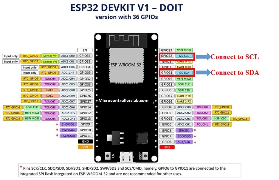
ESP32 I2C Pins
The I2C pins stated above are set in default. If we want to change the GPIO pins we have to set them in code. The diagram below shows the pinout for the ESP32.
Components Required:
We will need the following components to connect our ESP32 board with the OLED Display.
- ESP32 board
- SSD1306 OLED Display
- Connecting Wires
- Breadboard
Schematic ESP32 with OLED
Follow the schematic diagram below for the ESP32 module and connect them accordingly.
You may like to read:
OLED Display Interfacing with ESP32 – Display Text, Draw shapes and Images
Arduino Sketch ESP32 Client
Open your Arduino IDE and go to File > New. A new file will open. Copy the code given below in that file and save it. This code sets the ESP32 in station mode. Additionally, it makes HTTP requests on IP_ADDRESS/temperature, IP_ADDRESS/humidity, and IP_ADDRESS/pressure URLs and displays the sensor data received from the ESP32 server side on the OLED display.
#include <WiFi.h>
#include <HTTPClient.h>
#include <Wire.h>
#include <Adafruit_GFX.h>
#include <Adafruit_SSD1306.h>

const char* ssid = "ESP32-Soft-accessPoint";
const char* password = "microcontrollerslab";

const char* temperature_server = "http://192.168.4.1/temperature";
const char* humidity_server = "http://192.168.4.1/humidity";
const char* pressure_server = "http://192.168.4.1/pressure";

#define SCREEN_WIDTH 128
#define SCREEN_HEIGHT 64

Adafruit_SSD1306 display(SCREEN_WIDTH, SCREEN_HEIGHT, &Wire,-1);

String temperature;
String humidity;
String pressure;

unsigned long last_time = 0;
const long Delay = 10000;

void setup() {
  Serial.begin(115200);
  display.begin(SSD1306_SWITCHCAPVCC, 0x3C);

  display.clearDisplay();
  display.setTextColor(WHITE);

  WiFi.begin(ssid, password);
  Serial.println("Connecting");
  while(WiFi.status() != WL_CONNECTED) {
    delay(500);
    Serial.print(".");
  }
  Serial.println("");
  Serial.print("Connected to WiFi network with IP Address: ");
  Serial.println(WiFi.localIP());
}

void loop() {
  unsigned long current_time = millis();
  if(current_time - last_time >= Delay) {
    if(WiFi.status()== WL_CONNECTED ){
      temperature = HTTP_Request(temperature_server);
      humidity = HTTP_Request(humidity_server);
      pressure = HTTP_Request(pressure_server);
      Serial.println("Temperature: " + temperature + " *C - Humidity: " + humidity + " % - Pressure: " + pressure + " hPa");

      display.clearDisplay();
      display.setTextSize(1);
      display.setTextColor(WHITE);
      display.setCursor(0,0);
      display.print("Temperature: ");
      display.print(temperature);
      display.print(" ");
      display.setTextSize(1);
      display.cp437(true);
      display.write(248);
      display.setTextSize(1);
      display.print("C");

      display.setTextSize(1);
      display.setCursor(0, 25);
      display.print("Humidity: ");
      display.print(humidity);
      display.print(" %");

      display.setTextSize(1);
      display.setCursor(0, 50);
      display.print("Pressure: ");
      display.print(pressure);
      display.print(" hPa");

      display.display();

      last_time = current_time;
    }
    else {
      Serial.println("WiFi got disconnected!");
    }
  }
}

String HTTP_Request(const char* server_name) {
  WiFiClient client;
  HTTPClient http;
  http.begin(client, server_name);
  int httpResponseCode = http.GET();

  String payload = "--";

  if (httpResponseCode>0) {
    Serial.print("HTTP Response code: ");
    Serial.println(httpResponseCode);
    payload = http.getString();
  }
  else {
    Serial.print("Error code: ");
    Serial.println(httpResponseCode);
  }
  http.end();

  return payload;
}
How the Code Works?
Including Libraries
Firstly, we will include all the following libraries which are required for this project. The WiFi.h and HTTPClient.h will be used to connect to the wireless network and for HTTP communication. Additionally, Wire.h will allow us to communicate through the I2C protocol. Whereas the other libraries are the ones which we previously installed and are required for the proper functionality of the OLED display.
#include <WiFi.h>
#include <HTTPClient.h>
#include <Wire.h>
#include <Adafruit_GFX.h>
#include <Adafruit_SSD1306.h>
Setting Network Credentials
Now, specify the same network credentials which were defined in the ESP32 server Arduino sketch. Make sure they match otherwise the ESP32 client will not be able to connect with the ESP32 server’s wireless network.
const char* ssid = "ESP32-Soft-accessPoint";
const char* password = "microcontrollerslab";
Defining URLs for Making Requests
Next, define three global variables for each URL where the client will make the HTTP request. These are /temperature, /pressure and /humidity. Specify the ESP32 server IP address that we obtained previously in the URL. Remember to replace it with yours.
const char* temperature_server = "http://YOUR_SERVER_IP_ADDRESS/temperature";
const char* humidity_server = "http://YOUR_SERVER_IP_ADDRESS/humidity";
const char* pressure_server = "http://YOUR_SERVER_IP_ADDRESS/pressure";
Defining OLED Display
We will first define the width and height of our OLED display in pixels. We are using a 128×64 display hence the width will be 128 and the height will be 64.
#define SCREEN_WIDTH 128
#define SCREEN_HEIGHT 64
Next, we will initialize the display by creating an object of Adafruit_SSD1306 and specifying the width, height, I2C instance (&Wire), and -1 as parameters inside it.’ -1′ specifies that the OLED display which we are using does not have a RESET pin. If you are using the RESET pin then specify the GPIO through which you are connecting it with your development board.
Adafruit_SSD1306 display(SCREEN_WIDTH, SCREEN_HEIGHT, &Wire, -1);Defining Variables
We will create three variables of type string that for each sensor reading obtained from the ESP32 server side.
String temperature;
String humidity;
String pressure;
Adding Delay
The client will request sensor readings after every 10 seconds. We will incorporate this value in the Delay variable in milliseconds.
unsigned long last_time = 0;
const long Delay = 10000;
setup()
Inside the setup() function, we will open a serial connection at a baud rate of 115200.
Serial.begin(115200);Moreover, we will also initialize the OLED display by using display.begin(). Make sure you specify the correct address of your display. In our case, it is 0X3C.
display.begin(SSD1306_SWITCHCAPVCC, 0x3C)Then, we will clear the buffer by using clearDisplay() on the Adafruit_SSD1306 object. Next, we will control the colour of the text by using the setTextColor() function and passing WHITE as an argument. If we have a dark background, we will display our text in white and if we have a bright background then we will display the text in black.
display.clearDisplay();
display.setTextColor(WHITE);
The following section of code will connect our ESP32 client board with the ESP32 server’s wireless network whose network credentials we already specified above. We will use the WiFi.begin() function. The arguments will be the SSID and the password which we defined earlier in the code. After a successful connection is established, the IP address of the client gets displayed on the serial monitor.
  WiFi.begin(ssid, password);
  Serial.println("Connecting");
  while(WiFi.status() != WL_CONNECTED) {
    delay(500);
    Serial.print(".");
  }
  Serial.println("");
  Serial.print("Connected to WiFi network with IP Address: ");
  Serial.println(WiFi.localIP());
}
loop()
Inside the loop() function the client will make the HTTP requests after every 10 seconds and display the sensor readings obtained from the server on the OLED display as well as on its serial monitor. This will be done with the help of HTTP_Request() function. This function takes in a single argument that is the server name and returns the sensor reading from the ESP32 server in the form of a string variable.
 String HTTP_Request(const char* server_name) {
  WiFiClient client;
  HTTPClient http;
  http.begin(client, server_name);
  int httpResponseCode = http.GET();

  String payload = "--";

  if (httpResponseCode>0) {
    Serial.print("HTTP Response code: ");
    Serial.println(httpResponseCode);
    payload = http.getString();
  }
  else {
    Serial.print("Error code: ");
    Serial.println(httpResponseCode);
  }
  http.end();

  return payload;
}
We will call this function after every 10 seconds and specify the URLs that we initially defined as parameters inside it. The responses will get saved in the respective variables for temperature, pressure and humidity.
 unsigned long current_time = millis();
  if(current_time - last_time >= Delay) {
    if(WiFi.status()== WL_CONNECTED ){
      temperature = HTTP_Request(temperature_server);
      humidity = HTTP_Request(humidity_server);
      pressure = HTTP_Request(pressure_server);
These values we will display in the serial monitor.
Serial.println("Temperature: " + temperature + " *C - Humidity: " + humidity + " % - Pressure: " + pressure + " hPa");Displaying Sensor Readings on the OLED Display
Additionally, to display the sensor readings on the OLED display we will use the following lines of code. First, we will display the temperature reading with its unit. Next, we will display the humidity reading with its unit. Lastly, we will display the pressure reading with its unit.
We will set the size of the text using setTextSize() and pass the size as a parameter inside it. 1 denotes the smallest size and it increases relatively after incrementing it. We have set the font size as default which is 1. Whenever we increase the size by +1, the pixel resolution of the text increases by 10 in height.
Next, we will control the colour of the text by using the setTextColor() function and passing WHITE as an argument. If we have a dark background, we will display our text in white and if we have a bright background then we will display the text in black.
We will use the setCursor() function to denote the x and the y axis position from where the text should start. We have passed (0,0) as the parameter for the first reading hence the text starts from the upper left corner. The first parameter is the x-axis position that (+x) increases towards the right. The second parameter is the y-axis position that (+y) increases downwards. Then by using print() we will pass the text which we want to display on the OLED. We will set the cursor again at different positions to display the next readings. We will call the display() function on the display object so that the text displays on the OLED.
      display.clearDisplay();
      display.setTextSize(1);
      display.setTextColor(WHITE);
      display.setCursor(0,0);
      display.print("Temperature: ");
      display.print(temperature);
      display.print(" ");
      display.setTextSize(1);
      display.cp437(true);
      display.write(248);
      display.setTextSize(1);
      display.print("C");

      display.setTextSize(1);
      display.setCursor(0, 25);
      display.print("Humidity: ");
      display.print(humidity);
      display.print(" %");

      display.setTextSize(1);
      display.setCursor(0, 50);
      display.print("Pressure: ");
      display.print(pressure);
      display.print(" hPa");

      display.display();
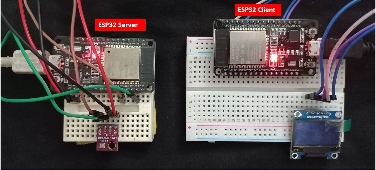
ESP32 Server-Client WiFi Communication Demonstration
Now let us demonstrate our project. Make sure both the ESP32 server and ESP32 client boards are powered on and their respective codes uploaded on them.
To see the demonstration, upload the above code to Arduino. Before uploading the code, make sure to select the ESP32 board from Tools > Board and also select the correct COM port to which the ESP32 client board is connected from Tools > Port.
Once the code is uploaded to ESP32 client, open its serial monitor. You will be able to see the sensor readings being obtained from the server side after every 10 seconds.
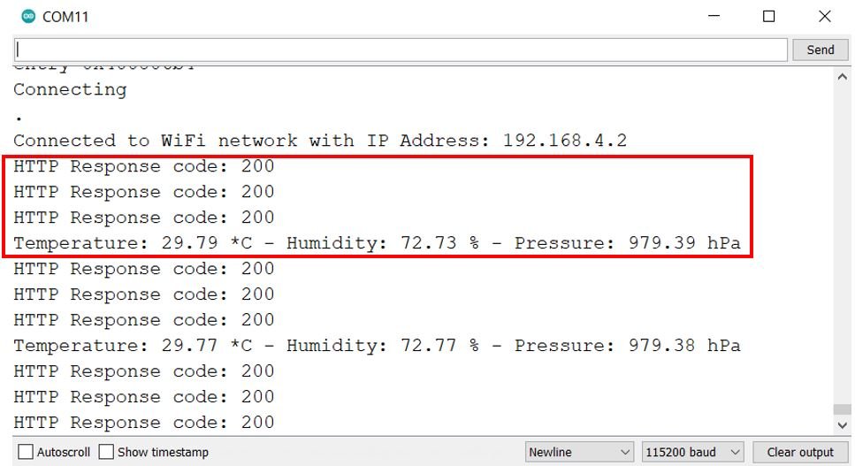
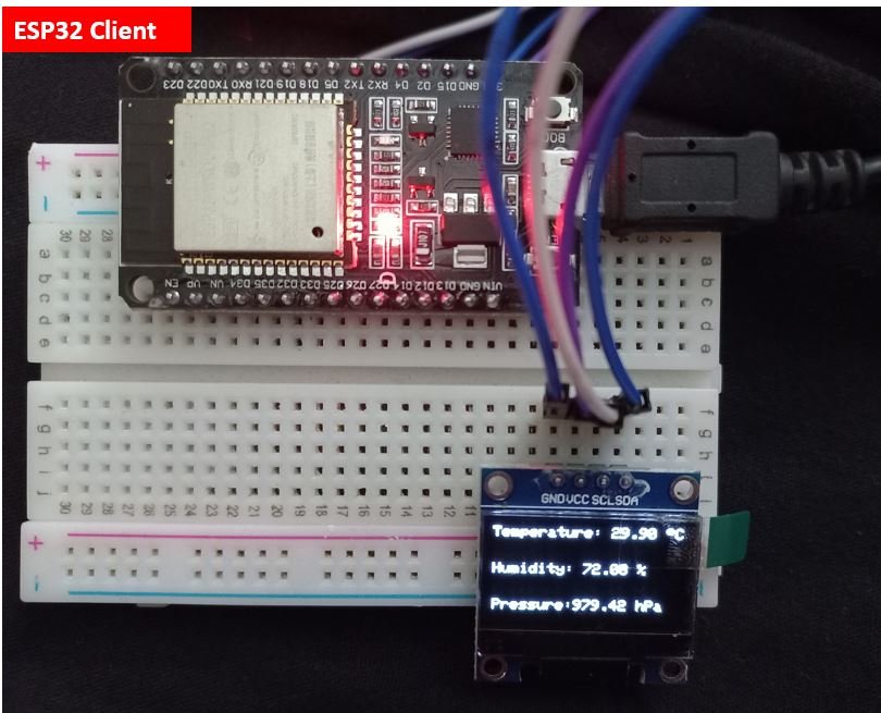
In the OLED display, new readings for temperature, humidity, and pressure keep updating after every 10 seconds. This can be clearly seen in the picture below.
Conclusion
In conclusion, we were effectively able to send HTTP GET requests from one ESP32 board to another and receive a response to it as well. This was achieved by using two ESP32 boards one that acted as a server in AP mode and the other that acted as the client in station mode. Without the need for a physical router, the ESP32 client was able to send HTTP requests to the ESP32 server. The ESP32 server in return sent updated sensor readings acquired from a BME280 sensor as a response to the ESP32 client. For this Client-Server communication, we used BME280 sensor readings but this project can be implemented with any type of data transmission between the two boards.
You may like to read:
- ESP32 ESP-NOW Two way Communication (Arduino IDE)
- Connect ESP32 to EMQX Cloud MQTT Broker (Arduino IDE)
- ESP32 MQTT Client: Subscribe and Publish BME280 sensor readings on HiveMQ
- ESP32 Web based Serial Monitor (WebSerial Library)
- IBM Watson Cloud Platform with ESP32: Display sensor Readings
- AWS IoT MQTT with ESP32: Publish Sensor Readings