In this tutorial you will learn how to interface Holux M-89 GPS module with pic microcontroller. In this pic microcontroller tutorial, we will how we can connect GPS module with pic microcontroller to get different satellites data. GPS modules receives data from different satellites. It can receive latitude and amplitude from different satellites but it depends on the GPS module you are using. We are using Holux M-89 Gps Module in this tutorial. I have already posted a article on how to interface Holux Gr 89 Gps Module with Arduino, you may like to check it also. So in this tutorial you will learn how to interface Holux M-89 Gps Module with pic16f877a microcontroller and how to data GPS coordinates from any satellite. So now let’s first start with introduction to Holux M-89 Gps Module, their applications, features and operating voltages range. And how many satellites it can bring to use.
Introduction to Holux Gr 89 Gps Module
It is a small sized Module. It has dimensions of 25.4 * 25.4 * 3 mm. It has very low power consumption. We can turn it on and off with the help of microcontroller by interfacing a transistor with power pin. It has many applications in embedded systems based projects like mobile phones, GPS locator, GPS based vehicle tracking system and many other microcontroller based project. Some key features of this GPS module is given below:
- It has a very small size
- It has very high sensitivity and resolution upto -159 dBm.
- It can track and connect up to 32 channels. So we can get data from 32 satellites with the help of this Holux Gr 89 Gps Module.
- It has very fast response rate to get data from satellites and fix the position very fast.
- It has very low power consumption.
- It supports NMEA0183 V 3.01 data protocol
- It can be used for navigation system.
- It can also be used to measure life pattern of animals with the help of GPS based data logger.
Holux Gr 89 Gps Module pin out
Pin out details of this GPS module is given below:

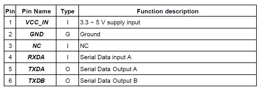
- Pin Number 1 is used to provided power supply to module. It has wide operating voltage range between 3.3v to 5V. This wide operating voltage range is very useful for us. Because we can connect pic microcontroller directly with this module. We do not need to use any voltage converter circuit between microcontroller and Holux M-89 GPS module.
- Pin Number 2 is ground pin.
- Pin Number 3 is free.
- Pin Number 4 is serial data receive pin. Holux M-89 GPS module transmit and receive data to serial communication. RXDA pin is used to receive data from any other device. For example, if we want to send any command from pic microcontroller to this module. We will connect pic microcontroller transmit pin Tx with RXDA pin of this module.
- Pin Number 5 and Pin Number 6 are serial data transfer pins. It is used to send data to other device for example pic microcontroller in our case. It will transmit the date received from other satellites through this pin and pic microcontroller will receive this data through UART serial communication.
So this is all about introduction to Holux M-89 GPS module and its pin description. Now I will show you a circuit diagram and code of Houlux M-89 GPS module interfacing with pic microcontroller. You can use any microcontroller. Concept will remains same, but you have to write code according to your choice of microcontroller.
Holux M-89 GPS module interfacing with pic microcontroller
As I have already explained earlier Holux M-89 GPS module communicate through UART serial communication. So to interface this module with pic microcontroller, you should know how to use UART serial communication of pic microcontroller to transmit and receive data. Interfacing circuit diagram is give below:

As shown in above circuit diagram, I have connected Tx pin of pic microcontroller with RXD pin of gsm module and TXD pin of GPS module with RX pin of pic microcontroller. Also make sure to connect ground terminals of pic microcontroller and GPS module with each other. Otherwise pic microcontroller will not be able to receive data from GPS module. So now I will show you how to receive satellites data. For demonstration purpose, I will be using proteus. With proteus virtual terminal we can check what we are sending and what we are receiving through serial communication. We can connect GPS module with our computer through USB to TTL converter and through COMPIM of proteus we can use it in simulation as well. This is a advantage of proteus, we can connect wireless communication modules with proteus with the help of COMPIM and check its results real time.
When you power up this module, it will simply start receiving data from different satellites. As soon as it receives data from satellites, it will send this data to its Transmit pin. In our, transmit pin is connect with receive pin of pic microcontroller. so we will receive data through microcontroller serial receiver. So we only need to write a code to receive data from other device. Simple example of code is given below:
Code to receive data from GPS module
char uart_rd;

void main() {
  ANSEL  = 0;                     // Configure AN pins as digital
  ANSELH = 0;

  UART1_Init(9600);               // Initialize UART module at 9600 bps
  Delay_ms(100);                  // Wait for UART module to stabilize

  UART1_Write_Text("Start");
  UART1_Write(10);
  UART1_Write(13);

  while (1) {                     // Endless loop
    if (UART1_Data_Ready()) {     // If data is received,
      uart_rd = UART1_Read();     // read the received data,
      UART1_Write(uart_rd);       // and send data via UART
    }
  }
}
With the help of this code we will receive data and whatever we will receive, we will display it on virtual terminal on proteus as shown below.

Video lecture
As you can see we are receiving data from many satellites and we can pick one satellite as our satellite and get coordinates according to it. For example we can use $GPGGA satellite and use to it get gps coordinates and date time as well. But you have to write a code to get gps coordinates and time from $GPGGA string. you can do it very easily with the help of string parsing in c language. I have written a code for it where I am getting Latitude and Longitude and time and displaying it on LCD as shown below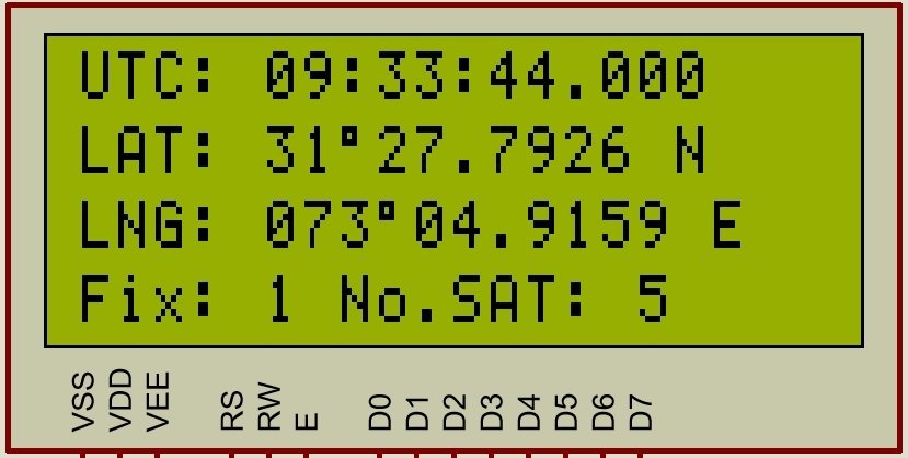
So this is all about Holux M-89 GPS module interfacing with pic microcontroller and how easily we can use this module to make our GPS based project. We can also make a GPS based clock with the help of this tutorial.
you may like to check other GPS based projects:
hello sir could you send me the source code for this project pleas .. i have been working same kind of project for my school project. could you help me in this one.
you can check source code from here
http://microcontrollerslab.com/gps-co-ordinates-lcd-pic-microcontroller/