shock sensor module interfacing with pic microcontroller, In this article, I am going to talk about the shock sensor or vibration detection sensor module. The shock sensor module as its names suggest is used to detect shocks. It is also known as a vibration sensor. In this shock detection project, we will see how the shock detection sensor works? How to interface it with pic microcontroller and how we can use it in real time embedded systems projects. I will be using pic16F877A microcontroller. 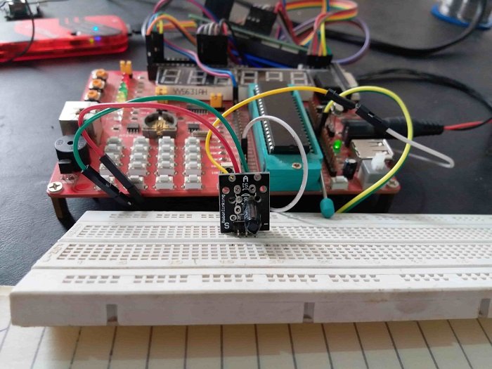
you may also like to check following sensor interfacing with pic microcontroller
- rotary encoder interfacing
- sound sensor interfacing
- ultrasonic sensor interfacing
- motion sensor interfacing
What is Shock Sensor Module?
The shock sensor module is such type of sensor which senses the shock, vibration, knocks or tap of anything. If the shock or vibration is excess from the limit then it gives the alarm signal to buzzer as well as with allowing the circuit, controller or device to detect this vibration or shock. This shock sensor module is also known as a vibration sensor and it has different types. These types are easily available in the online shops. Every shock sensor module almost covers the six square meter distance from each side of mounting thing, therefore, they are very useful for security purposes. They are easily installed at windows or main gate of any building or house for security purposes. A simple shock sensor module is shown in figure 1

Figure 1 Simple Shock Sensor Module
Pin Configuration of Shock Sensor Module
Every shock sensor module consists of three pins. Two pins are used for power on this module such as positive 5 volts and ground. The third pin is used for sensing the vibration and giving the logic high signal to any type of controller such as a microcontroller or Arduino etc. shown in figure 2.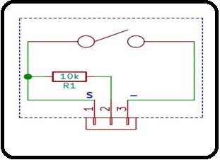
Figure 2 Shock Sensor Module Pins
Normally, a shock sensor module is installed in two configurations such as pull-down resistor configuration and pull up resistor configuration. In pull-down resistor configuration, a 10k ohm resistor is connected in between pin 1 and 2, pin 3 is used for positive supply and pin 2 is also used for ground. Similarly, in pull-up resistor configuration 10K ohm resistor is also connected between 1 and 2 but positive supply voltages are applied at pin 2 and pin 3 is connected to ground. One thing should keep in mind during the installation of this shock sensor module that which configuration is suitable for your micrcontroller. The user can easily check each configuration from multimeter before use. Both configurations are shown in figure 3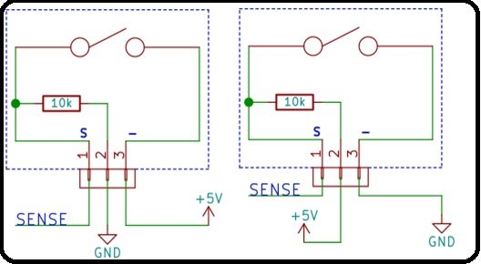
Figure 3 Pull Down Resistor Configuration Pull Up Resistor Configuration
Working Principle of Shock Sensor Module
The working principle of the shock sensor module is very simple. When anyone touch, hit, mover or jolt the thing where shock sensor module has installed then this sensor sends the signal to their brain or controller for indicating the intensity of this hit, move or touch. Similarly, depending on this intensity, the brain or controller sends a logic high signal to a buzzer, beep or sound system. Two methods are used for installing the shock sensor module which we have described in detail in the above paragraph. For installing this shock sensor module two metal contacts are used and along with these contacts shock sensor is installed, and we can configure these contacts with a simple switch. When any on touch these contacts then shock sensor pins are short then current flow these pins. During this, the sense pin means third pin sense this current and sends a logic high signal to the brain or microcontroller. Then alarm or beep would be turned on according to the intensity of touch, move or vibration.
How to Interface Shock Sensor Module with PIC16f877a Microcontroller
For acquiring proper advantages or benefits, a brain or controller is required with this shock sensor module. Different controllers such as a microcontroller or Arduino etc. have been using with shock sensor. But here, we will explain it with pic microcontroller PIC16F877A. This controller consists of four ports and shock sensor could be contacted with any port, but that port is configured as an input port in programming. It is programmed in c language with the help of mikro/c software and is powered up with 5 volts dc voltages. Similarly, when it is connected with microcontroller then during any movement, vibration or jolt then microcontroller receives the logic low signal from sense pin of shock sensor.
Because the shock sensor module we are using is an active low shock sensor module. an alarm system or buzzer is connected at the output of the microcontroller, therefore, the microcontroller would be turned on or off the alarm or buzzer after some processing the logic low signal. Because the shock Microcontroller is the main intelligent controller with the shock sensor module, therefore, it has done all the work more precisely and efficiently during an emergency situation.
so to interface shock sensor with pic16f877a microcontroller, we need to use one digital input pin of a microcontroller. I have pin number 5 of PORTB as a digital input pin. If you don’t know how to use digital input-output pins of pic microcontroller I recommend you to check this article.
PORTD of pci16F877A microcontroller is used as a digital output. Whenever microcontroller detects a shock, digital output pins of PORTD goes high and also alarm connected with PORTE pin number zero starts giving sound. For more information check the project demonstration in the video given below:
Program for a shock sensor module
sbit LCD_RS at RD2_bit;
sbit LCD_EN at RD3_bit;
sbit LCD_D4 at RD4_bit;
sbit LCD_D5 at RD5_bit;
sbit LCD_D6 at RD6_bit;
sbit LCD_D7 at RD7_bit;

sbit LCD_RS_Direction at TRISD2_bit;
sbit LCD_EN_Direction at TRISD3_bit;
sbit LCD_D4_Direction at TRISD4_bit;
sbit LCD_D5_Direction at TRISD5_bit;
sbit LCD_D6_Direction at TRISD6_bit;
sbit LCD_D7_Direction at TRISD7_bit;

#define REA PORTB.B4 // Rotary encoder pin definition
#define REB PORTB.B5

void main() {

TRISB.B4=1; // set rotary encoder pins to input
TRISB.B5=1;
TRISD=0X00;
PORTD=0X00;

// inilized the LCD
//Lcd_Init(); // Initialize LCD
//Lcd_Cmd(_LCD_CLEAR); // Clear display
//Lcd_Cmd(_LCD_CURSOR_OFF); // Cursor off
//Delay_ms(100); // Wait for UART module to stabilize
TRISE.B0=0;
PORTE.B0=1;

Lcd_Out(1,1,"shock sensor");
// display count to lc
while(1)
{
if (REB==0)
{

//Lcd_Out(2,1,"shock detected ");
PORTE.B0=0;
PORTD=0XFF;
delay_ms(1000);
}
else
{
//Lcd_Out(2,1,"No shock detected");
PORTE.B0=1;
PORTD=0X00;
}
//delay_ms(10);

}

}
you may also like to read about other sensors interfacing with pic microcontroller:
- Pic microcontroller tutorials
- Pic microcontroller projects
- Relay module interfacing with pic microcontroller
- Rotatory encoder interfacing with pic microcontroller
- Sound detection module interfacing with pic microcontroller
- AC load interfacing with pic microcontroller
- magnetic field strength determination using PIC18F46K22
- joystick module interfacing with pic microcontroller
- Mercury tilt switch interfacing with pic microcontroller
- flame sensor interfacing with pic microcontroller
- raindrop sensor connection with pic18f46k22
- Gas sensor with pic microcontroller
- Soil moisture sensor interfacing with pic microcontroller
Hello. Do you have a project file in proteus and .hex? It would be interesting to take a look.