PIC Microcontroller Comparator: If we talk about the comparator in electronic language, it is an analog device that compares two signals, which could be in the form of voltage or current. One of these signals can be a triangular wave, a sawtooth wave, or any other wave, while the other can be steady-state DC voltages or any other type. To compare these signals, their voltage levels should be different. The output of the comparator is a digital signal that indicates which signal is larger. Analog comparators have numerous applications. In this case, we will focus on the comparator built into the PIC microcontroller for multiplexing or comparing inputs with the I/O pins. This integration saves costs and simplifies the design process.
Comparator Peripherals in Pic Microcontrollers
Comparator peripherals in PIC microcontrollers are hardware modules that enable you to compare two analog voltage levels and generate an output based on the comparison result. These modules are often referred to as “comparators”. They are commonly used in applications where you need to make decisions based on voltage levels. Different Pic microcontrollers have different numbers of comparators.
PIC16F877A Comparators Channels
The PIC16F877A microcontroller contains two built-in analog comparator channels. The analog comparators in the PIC16F877A are responsible for comparing two analog voltages.
Pins
In terms of hardware integration, the analog comparators multiplex the input pins with I/O port pins RA0 through RA3. This allows for convenient connectivity with external analog signals. On the output side, pins RA4 and RA5 multiplex the comparator outputs, further simplifying the circuit design.
Register
To control and configure the behavior of the analog comparators, the CMCON register (Comparator Module control register) is utilized. This register enables the programmer to select the desired operating mode for each comparator, set the reference voltage levels, and configure additional functionalities if needed.
Control Register of PIC microcontroller Comparator.
The PIC microcontroller consists of a CMCON control register, which has seven bits shown in the figure

Figure 1 Comparator Control Register
Bit 7 (C2OUT): Bit 7 in this PIC microcontroller comparator control register 7 shows the comparator 2 indication output, which would be 1 when the Vin+ is greater than Vin- in mathematical words 1 = C2Vin+ > C2Vin-. Similarly, the comparator would show the output 0 when the Vin+ is less than Vin-, same in mathematical words 0 = C2 Vin+ < C2Vin-.
Bit 6 (C1OUT): This is the comparator 1 indication output bit. The operation of this comparator is the same as comparator 2. This bit shows 1 when input 1 is greater than input 2 and shows 0 when input 1 is less than input 2. In mathematical terms, it indicates that 1 = C1Vin > C1Vin- and 0 = C1Vin < C1Vin-.
Bit 5,4 (U-0, U-0): These are the unimplemented bits. During the operation of the comparator, the control register reads these bits as 0.
Bit 3 (CIS): This bit is actually a control input switch, which is for controlling the input and output modes of the comparator.
Bit 2, 1, 0 (CM2, CM1, CM0): These are the comparator modes of control, which are controlled by the CIS switch bit.
Configuration Modes
The PIC microcontroller comparator operates in eight modes, and the CMCON control register selects these modes. The direction of data in the controller is controlled by the TRIS register, indicating the input and output of pins in the controller. Changing the comparator mode of operation may result in the output level not being valid for other modes of operation, as different devices have different electrical specifications or output levels. It is important to disable the comparator interrupt when changing the mode of operation, otherwise, the comparator may generate false interrupts. Figure 3 illustrates the comparator modes of operation.

Comparator Modes of Operations
Here is an explanation of the different comparator modes shown in the picture:
- Mode 1: This mode resets both comparators by setting the bits CM2, CM1, and CM0 to 0, 0, and 0, respectively.
- Mode 2: In this mode, both comparators are turned off by setting the bits CM2, CM1, and CM0 to 1, 1, and 1, respectively.
- Mode 3: This mode enables independent operation of both comparators by setting the bits CM2, CM1, and CM0 to 1, 0, and 0, respectively.
- Mode 4: In this mode, both comparators work in multiplexing mode by combining the four inputs into two inputs. The bits CM2, CM1, and CM0 are set to 0, 1, and 0, respectively.
- Mode 5: This mode allows both comparators to use a common reference signal by setting the bits CM2, CM1, and CM0 to 0, 1, and 1, respectively.
- Mode 6: In this mode, both comparators use the output signal as a reference by setting the bits CM2, CM1, and CM0 to 1, 1, and 0, respectively.
- Mode 7: This mode enables the first comparator to work independently while connecting the second comparator to the ground by setting the bits CM2, CM1, and CM0 to 1, 0, and 1, respectively.
- Mode 8: In this mode, the two comparators work in a multiplexing mode by multiplexing three inputs into two inputs. The bits CM2, CM1, and CM0 are set to 0, 0, and 1, respectively.
These different modes allow you to configure the behavior of the comparators in the PIC microcontroller based on your specific requirements and application.
How Does Comparator Work?
A single PIC microcontroller comparator, along with two analog inputs that have different voltage levels, and one digital output, is shown in Figure below.
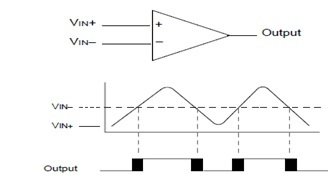
According to the above figure, the VIN+ and VIN- are the two analog inputs. When the analog input VIN+ is less than the analog input VIN-, the digital output of a single comparator will be at a low level, or zero. Similarly, when the analog input VIN+ is greater than the analog input VIN-, the digital output of a single comparator will be at a high level, or the maximum level. In Figure 3, the shaded area represents the uncertainty due to the offset input and response time.
Reference of Comparators
The reference of a comparator is basically an analog signal that could be an internal or external reference signal, depending on the mode of operation of the microcontroller comparator. In microcontrollers, the comparator adjusts the digital output signal according to the reference analog input signal. In Figure 3, the VIN- signal is compared with the VIN signal. Therefore, we can say that the VIN- is the reference signal of a single comparator.
Time Response of a Comparator
The minimum amount of time required to show the guaranteed digital output of a comparator after selecting a new reference signal or source voltage is called time response. If you change the internal reference signal, you should also consider the settling time for the desired output. Otherwise, you can use the microcontroller’s comparator time response.
Outputs of Comparator
The CMCON control register reads the outputs of the comparator directly, but it only allows for reading these bits. You can directly take the comparator output from the I/O pins. The comparator output block diagram shows the I/O pins of the comparator.
PIC Microcontroller Comparator Analog Input Connection
In the figure below, we use a simple circuit for the analog input connection of the pic microcontroller comparator.

According to the figure, the digital outputs have reverse-biased diodes connecting them to the analog inputs. You must attach the analog inputs between the VDD and VSS. If the analog input voltage deviates from the range of 0.6 volts in any direction, it may forward-bias one of the diodes and cause a latch-up. We recommend maintaining a maximum source impedance of 10 KΩ for the analog source.
Pic Microcontroller Comparator Example Code
The code for this project is written in the MIKROC compiler. If you do not know how to use MikroC for Pic, you can refer to these tutorials:
- How to Use “MikroC PRO for PIC” to Program PIC Microcontrollers
- Pic microcontroller programming in c using Mikroc Pro for PIC
void main()
{
  // Configure PORTC as output
  TRISC = 0;

  // Configure input pins for the negative input of Comparator 1 and Comparator 2
  TRISA.RA0 = 1; // Negative input of Comparator 1
  TRISA.RA1 = 1; // Negative input of Comparator 2

  // Configure input pins for the positive input of Comparator 1 and Comparator 2
  TRISA.RA2 = 1; // Positive input of Comparator 1
  TRISA.RA3 = 1; // Positive input of Comparator 2

  // Configure output pins for the output of Comparator 1 and Comparator 2
  TRISA.RA4 = 0; // Output of Comparator 1
  TRISA.RA5 = 0; // Output of Comparator 2

  // Set the Comparator Module to 'Two Common Reference Comparators with Outputs' Mode
  CMCON = 0x05;

  while(1)
  {
    // Assign the output of Comparator 2 to RC0
    PORTC.F0 = CMCON.C2OUT;

    // Assign the output of Comparator 1 to RC1
    PORTC.F1 = CMCON.C1OUT;

    // Delay for 100 milliseconds
    Delay_ms(100);
  }
}
This code configures a PIC microcontroller to utilize its comparator modules for comparing analog voltage levels. Initially, it sets up the I/O configurations: it configures PORTC as an output, and it configures several pins on PORTA as inputs for the negative and positive inputs of two comparator modules, namely Comparator 1 and Comparator 2. Additionally, it designates pins on PORTA as outputs for the comparator results.
The CMCON register sets the value (0x05) to configure the comparator module in the “Two Common Reference Comparators with Outputs” mode, which implies that both Comparator 1 and Comparator 2 share the same reference voltage and generate output signals.
Inside the infinite while loop, the code reads the output states of both Comparator 1 and Comparator 2 (CMCON.C1OUT and CMCON.C2OUT) and assigns them to PORTC pins, specifically, RC1 and RC0. The code also includes a delay of 100 milliseconds between these assignments. Essentially, this code continuously monitors the voltage levels on the comparator input pins, performs comparisons, and reflects the results by setting or clearing the corresponding output pins on PORTC. However, the behavior and effectiveness of this code would depend on the specific voltage levels applied to the comparator input pins and the configured reference voltage, which are not specified in the given code.
Application of PIC Microcontroller Comparator
- The PIC microcontrollers use three or four-stage battery chargers to check the battery voltage at every moment in time.
- The PIC microcontrollers also use analog-to-digital converters in which the comparator converts the analog signal into a digital signal.
You may also like to read:
- Program Pic Microcontrollers with MikroC for Pic Compiler
- Setting Configuration Bits Of Pic Microcontroller
- types of oscillator used in microcontrollers
- Memory Organization in PIC Microcontrollers
- pic microcontroller comparator and how to use it
- USB interfacing with PIC microcontroller with code
- Arduino Comparator Tutorial with Example
- LM339 Quad Differential Comparator IC