In this pic microcontroller tutorial, you will learn how to interface active and passive buzzer modules with any pic microcontroller. What is the difference between active and passive buzzer? What is a pin configuration of the active and passive buzzer? Working of these modules and How to interface buzzer with pic16f877a microcontroller? These little buzzers have many applications in electrical engineering projects, embedded systems projects, and pic microcontroller projects. They can be used as an alarm in various systems. For example, in the magnetic field detection project and motion detection project and rain detector project, we used buzzer as an alarm when some wrong happens.
What is Active and Passive Buzzer?
Buzzers are mainly divided into two types first one is active buzzers and the second one is passive buzzers. In an active buzzer, additional circuitry is added to make the use it easier, but it only produces a single type of sound or tone. It required a dc power source for generating the sound or beep. Similarly, passive buzzer can generate different sounds or beep. It depends upon the frequency which is provided to this passive buzzer. For generating any type of sound, the desired frequency signal is provided to its oscillating circuit then it generates the desired frequency sound or beep.
It required an ac power source for generating the sound or beep. For identifying it is active or passive then this could check after supplying ac and dc voltages across the buzzer. Now the buzzers are available that could use as an active and passive buzzer just changing the command which is given to this through any type of controller. Such buzzers are called active standard passive buzzers. These are easily available in the market or online shop. A simple active standard passive buzzer is shown is figure1
Figure 1 Active Standard Passive Buzzer
Pin Configuration of Active and Passive Buzzer
Every active and passive buzzer consist of three pins such as GND, VCC and signal pin which is shown in figure 2. For power, on this active and passive buzzer, 3.3 volts to 5 volts are given to VCC pin and GND pin. These voltages could be given through any controller or power source and the third pin is because the signal pin, therefore, it is also powered up or given signal through a controller. Through this signal pin, the active and passive buzzer is turned on or off any time. This buzzer has a limited voice if anyone wants to increase the sound or loud the voice then a transistor is added with this buzzer. Sometimes it takes more current that could not possibly form controller. In this condition, an NPN or PNP transistor is added in the circuit for safely turning on or off the buzzer form controller. Normally the resistance of active and passive buzzer is 16 ohm. It takes 100 m amps or more current therefore this could be easily operated from transistor because any NPN or PNP transistor can easily drive .5Amps current.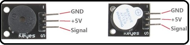
Figure 2 Passive and Active Configuration of Active Standard Passive Buzzer
Working Principle of Active and Passive Buzzer
The working principle of the active and passive buzzer is very simple. For operating it with any controller then the wiring of this buzzer is done according to its pin configuration which is mentioned in detail in the above paragraph. Actually, this buzzer consists of an electromagnetic speaker. When it is turned on through any controller then electromotive waves are generated in the form of sound. For operating it with active buzzer configuration, dc voltages are supplied this buzzer through dc power source. Similarly, for operating it in passive buzzer configuration ac voltages are supplied to this buzzer. Both types of voltages could be taken to this buzzer with any controller but the programming commands of both are different.
How to Interface Active and Passive Buzzer with PIC16f877a Microcontroller
Circuit diagram for buzzer module interfacing with pic16f877a microcontroller is shown below. 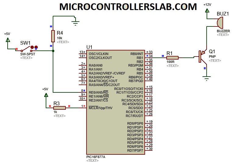
As we have discussed in the above paragraph, signal voltages are required to turn on or off the buzzer in an active and passive configuration. These signals voltages are given with the help of any controller such as Arduino or pic microcontroller. Here we shell give these voltages with the help of pic microcontroller. It is programmed in c language with the help Mikro/c software and powered up with 5 volts dc. To run this active standard passive buzzer in an active and passive configuration programming code is necessary for this. Each configuration has separate programming code to run the buzzer. This programming code is set only by the professional programmer. Pic microcontroller consists of four input-output ports and buzzer could be connected with any pin of any port, but that port is configured as an output port in programming code. Similarly, for gaining high beep or sound from this active standard passive buzzer a PNP or NPN transistor is added with the circuit as shown below:
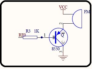 Check this article on how to use the transistor as a switch. One terminal of buzzer module is connected with +5 volt and another terminal is connected with a transistor. When a transistor is on, buzzer also becomes on and when the transistor is off, the buzzer is also off. Because there will be no path for current to flow.
Code
void main()
{
ADCON1=0X0F;  //. This define we want to use PORTE pins as digital pins
TRISB.B7=1;  // declares pin number seven of PORTB as a input pin
TRISE.B0=0;  // declares pin number zero of PORTE as a output pin
PORTB.B7=0;  // initialized it to zero or logic Low
while(1)
{
if (PORTB.B7==0)
{
PORTE.B0=0;
}
else
{
PORTE.B0=1;
}

}

}
For a complete demonstration, check the video:
Other sensors interfacing with pic microcontroller:
- Relay module interfacing with pic microcontroller
- Shock sensor interfacing with PIC16F877A
- Rotatory encoder interfacing with pic microcontroller
- Sound detection module interfacing with pic microcontroller
- AC load interfacing with pic microcontroller
- magnetic field strength determination using PIC18F46K22
- joystick module interfacing with pic microcontroller
- Mercury tilt switch interfacing with pic microcontroller
- flame sensor interfacing with pic microcontroller
- raindrop sensor connection with pic18f46k22
- Gas sensor with pic microcontroller
- Soil moisture sensor interfacing with pic microcontroller
Thanks for useful information
Could you please tell me which transistor is used here