In this IoT project, we will create an IoT based sound pollution monitoring system using ESP32, sound module, and Blynk app. We will use the KY-038 microphone sensor to detect sound in decibels and display sound in decibel on an OLED. Additionally, we will link our sound pollution monitor with Blynk application. To make our sound pollution monitor even more practical, users can monitor the sound decibels on the Blynk app. In other words, it becomes extremely handy to monitor the sound from anywhere through a mobile application. We will program our ESP32 board using Arduino IDE.
Prerequisites
We will require the following components for our sound pollution monitor.
Required Components:
- ESP32 development board
- Sound Sensor Module (KY-038)
- OLED Display
- Connecting Wires
We will use Arduino IDE to program our ESP32 development board. Thus, you should have the latest version of Arduino IDE. Additionally, you also need to install the ESP32 plugin.
If your IDE does not have the plugin installed you can visit the link below: Installing ESP32 library in Arduino IDE and upload code.
KY-038 Sound Sensor Module
The KY-038 sound sensor module consists of capacitance sensitive microphone (50Hz-10kHz) and an amplification circuit. The module converts sound waves to electrical signals.
It detects the sound with the help of a microphone and then feeds this sound to processing circuitry which consists of an operational amplifier LM393. It also consists of a potentiometer which is used for setting the sound level and by setting this sound level the output of this sound sensor module could be easily controlled. Similarly, the output of this sensor could be checked by connecting the LED or any other device at output pins.
There are two types of outputs accessible from this sensor, both digital output and analog output. The digital output is obtained when the sound is at a particular threshold value. The potentiometer is used to adjust the sensitivity of the digital output pin. When a particular sound will be higher/lower than the threshold level, the digital output will be low/high. In our case, the digital output will be HIGH and it will be LOW when the sound will be detected.
However, the analog output depicts the direct microphone signal as a voltage level that changes with the intensity of the sound.
Note: We will use the analog output pin for this project
IoT Sound Pollution Monitoring System Circuit Diagram
We will connect 3 pins of the KY-038 sound sensor module with ESP32. These include the VCC, GND, and AO pins. The VCC will be connected with the Vin pin from the ESP32. GND of both the devices will be in common. We will connect ADC pin 34 with AO. You can use any appropriate anlog pin of ESP32.
| ESP32 | KY-038 |
|---|---|
| Vin | VCC |
| GND | GND |
| GPIO34 | AO |
The OLED display has 4 terminals which we will connect with the ESP32 board. As the OLED display requires an operating voltage in the range of 3.3-5V hence we will connect the VCC terminal with 3.3V which will be in common with the ESP32 board. SCL of the display will be connected with the SCL pin of the module and the SDA of the display will be connected with the SDA of the module. By default, the I2C pin in ESP32 for SDA is GPIO21, and for SCL is GPIO22.
| ESP32 | OLED |
|---|---|
| GND | GND |
| Vin | VCC |
| GPIO22 (I2C SDA) | SCL |
| GPIO21 (I2C SCL) | SDA |
Assemble the devices as shown in the schematic diagram below:
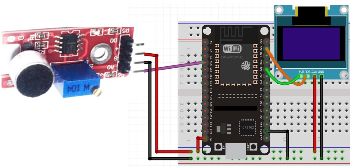
We have used the same connections as shown in the two tables above.
You may like to read:
Setting up Blynk Application for ESP32 Sound Monitor
To monitor sound on our smart phones we will create a project in the Blynk app and link it with our Arduino sketch. Blynk is a free-to-use app where the user can build software to control microcontrollers such as Raspberry Pi, Arduino, and ESP8266 NodeMCU, etc. Follow the series of steps given below to successfully configure the application.
Installing and Getting Ready
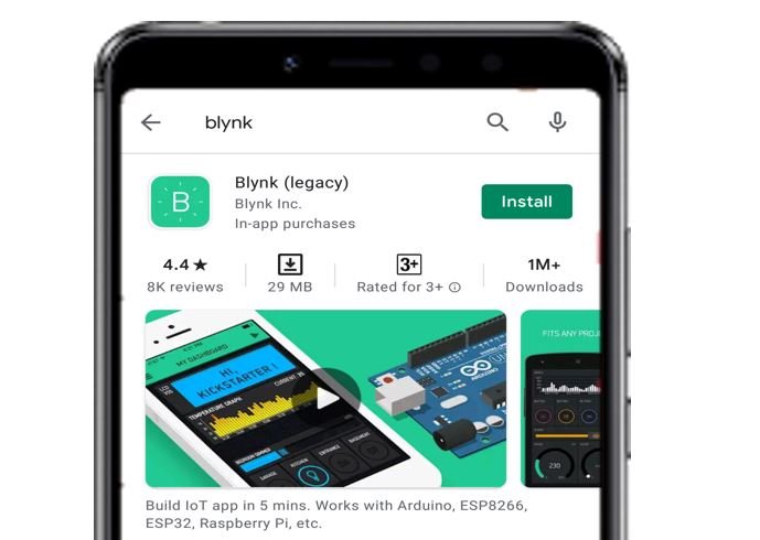
We will use an Android smartphone for this project. Go to Google Play or Apple Store (if using an iPhone).

Search for ‘Blynk’ and install the application.
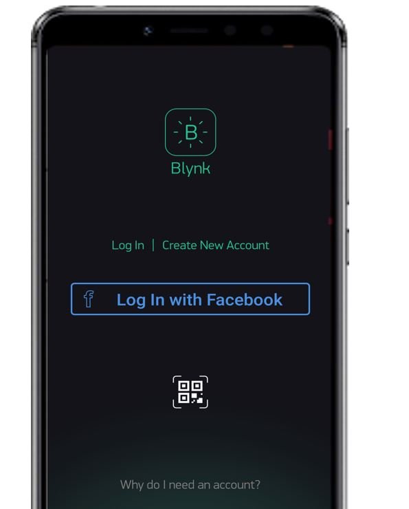
You will have to create an account to proceed further. You can also log in with your Facebook account if you possess that.
Creating Project
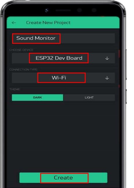
After you have successfully signed in the following window will appear. Click ‘New Project.’

Now specify the name of your project, device and connection type. After that press the ‘Create’ button.
You will receive a notification regarding your Authorization token. This can be accessed from the email account you signed in with and also through Project Settings.
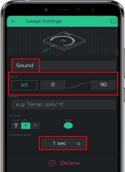
Now the Blynk canvas will open. Press on the screen. The widget box will appear. Press the ‘Gauge’ widget. You can view information regarding it by pressing the icon present in the far right.

Now click on this widget and the gauge settings appear. Choose the virtual pin V0 as an input pin. Set its range between 0-90. Additionally, set the reading rate to 1 second.
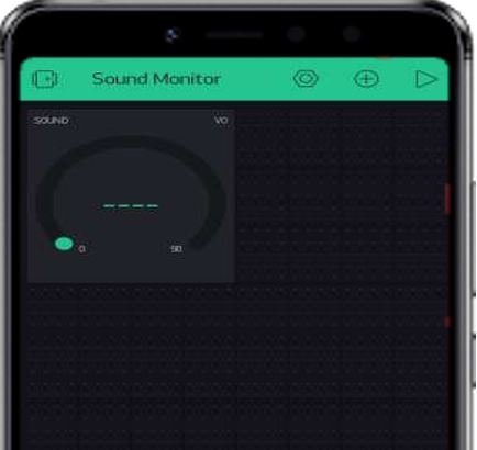
After you alter the settings of the gauge, the canvas will look something like this:
Installing Required Arduino Libraries for IoT Sound Pollution Monitoring System
We will use Arduino IDE to program our ESP32 development board. Make sure your Arduino IDE already has the ESP32 plugin installed. To program our ESP32 board for this sound monitor we will be required to install three libraries: BlynkSimpleEsp32.h, Adafruit_SSD1306.h and Adafruit_GFX.h
Installing Blynk Library
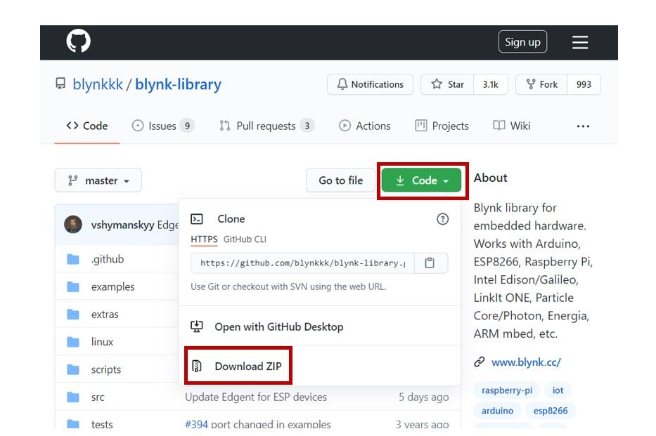
To use the Blynk app with our ESP32 board, we would have to install its library.
To download the library, click here. Click on ‘Code’ and then ‘Download Zip’.
You have to go to Sketch > Include Library > Add .zip Library inside the IDE to add the library as well. After installation of the library, restart your IDE.
Installing OLED Display Libraries
To use the OLED display in our project, we have to install the Adafruit SSD 1306 library and Adafruit GFX library in Arduino IDE. Follow the steps below to successfully install them.
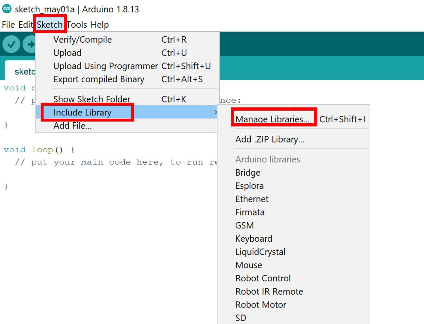
Open Arduino IDE and click on Sketch > Library > Manage Libraries
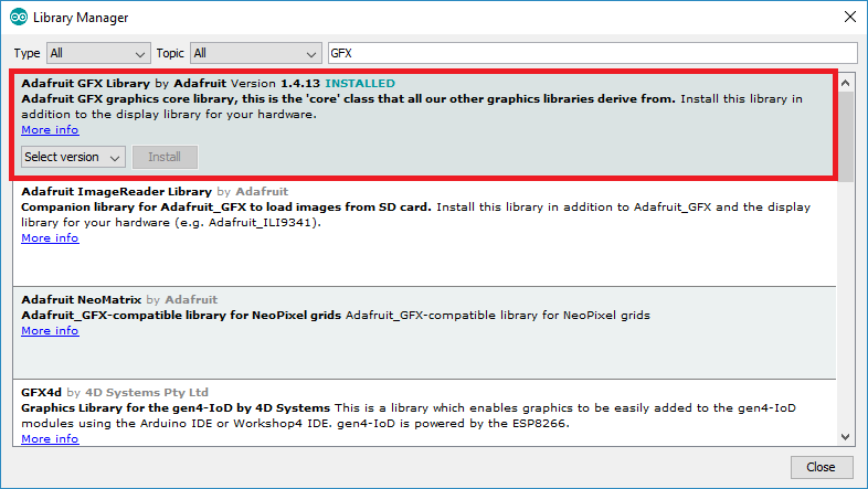
The following window will open up.

Type ‘SSD1306’ in the search tab and install the Adafruit SSD1306 OLED library.

We will also require the Adafruit GFX library which is a dependency for SSD1306. Type ‘Adafruit GFX’ in the search tab and install it as well.
After installation of the libraries, restart your IDE.
You may like to read:
Arduino Sketch IoT Sound Pollution Monitoring System
Open your Arduino IDE and go to File > New. A new file will open. Copy the code given below in that file and save it.
#define BLYNK_PRINT Serial
#include <WiFi.h>
#include <BlynkSimpleEsp32.h>
#include <Wire.h>
#include <Adafruit_GFX.h>
#include <Adafruit_SSD1306.h>

#define AO 34

Adafruit_SSD1306 display = Adafruit_SSD1306(128, 64, &Wire, -1);

unsigned int output;
int Decibels;

char auth[] = "eO3YD5N52-kdPn3-Ttqu6AfnG0Ik****";
char ssid[] = "YOUR_SSID";
char pass[] = "YOUR_PASSWORD";

BLYNK_READ(V0)
{
  Blynk.virtualWrite(V0, Decibels);
}

void setup() {
  Serial.begin(115200);
  pinMode (AO, INPUT);
  display.begin(SSD1306_SWITCHCAPVCC, 0x3C);
if(!display.begin(SSD1306_SWITCHCAPVCC, 0x3C)) {
  Serial.println(F("SSD1306 allocation failed"));
  for(;;);
}
  delay(2000);
display.clearDisplay();
display.setTextColor(WHITE);
  Blynk.begin(auth, ssid, pass);
}

void loop() {
  Blynk.run();
  unsigned long start_time = millis();
  float PeakToPeak = 0;
  unsigned int maximum_signal = 0;  //minimum value
  unsigned int minimum_signal = 4095;  //maximum value
  while (millis() - start_time < 50)
  {
    output = analogRead(AO);
    if (output < 4095)
    {
      if (output > maximum_signal)
      {
        maximum_signal = output;
      }
      else if (output < minimum_signal)
      {
        minimum_signal = output;
      }
    }
  }
  PeakToPeak = maximum_signal - minimum_signal;
  Serial.println(PeakToPeak);
  Decibels = map(PeakToPeak, 50, 500, 49.5, 90);

  display.setTextSize(2);
  display.setCursor(0,10);
  display.print(Decibels);
  display.setTextSize(2);
  display.setCursor(40,10);
  display.print("db");
  display.display();
  if (Decibels <= 50)
  { display.setTextSize(2);
    display.setCursor(0,30);
    display.print("LOW");
    display.display();
  }
  else if (Decibels > 50 && Decibels < 75)
  {
    display.setTextSize(2);
    display.setCursor(0,30);
    display.print("Moderate");
    display.display();
  }
  else if (Decibels >= 75)
  {
    display.setTextSize(2);
    display.setCursor(0,30);
    display.print("HIGH");
    display.display();
  }
  delay(1000);
  display.clearDisplay();
}
How the Code Works?
Firstly, we will include all the following libraries which are required for this project. The WiFi.h will be used to connect to the wireless network. The Wire.h will allow us to communicate through the I2C protocol. Whereas the other libraries are the ones which we previously installed and are required for the proper functionality of the OLED display and the Blynk application.
#define BLYNK_PRINT Serial
#include <WiFi.h>
#include <BlynkSimpleEsp32.h>
#include <Wire.h>
#include <Adafruit_GFX.h>
#include <Adafruit_SSD1306.h>
Next, we will define the ESP32 ADC pin which we have connected with AO pin of the sound sensor. It is GPIO34 in our case.
#define AO 34Then, we will initialize the OLED display by creating an object of Adafruit_SSD1306 and specifying the width, height, I2C instance (&Wire), and -1 as parameters inside it.’ -1′ specifies that the OLED display which we are using does not have a RESET pin. If you are using the RESET pin then specify the GPIO through which you are connecting it with your development board.
Adafruit_SSD1306 display = Adafruit_SSD1306(128, 64, &Wire, -1);We will define the authorization key which was emailed to us through Blynk in our account through which we logged in it. Keep this key safe with you for security concerns.
char auth[] = "eO3YD5N52-kdPn3-Ttqu6AfnG0I*****";Now, we need to define the SSID name and the password. Following lines set the name of SSID and password. You have to replace the SSID and password with your own network credentials.
char ssid[] = "YOUR_SSID";
char pass[] = "YOUR_PASSWORD";
The following BLYNK_READ() function takes in the input pin V0 (virtual pin) as a parameter inside it. Remember we had connected pin V0 with our gauge while setting up our project in Blynk. This function will be responsible to send decibel values to the virtual pin.
BLYNK_READ(V0)
{
  Blynk.virtualWrite(V0, Decibels);
}
setup()
Inside the setup() function, we will first configure the AO pin as an input pin.
pinMode (AO, INPUT);This will be done by using the pinMode() function. Then, we will initialize the OLED display by using display.begin(). Make sure you specify the correct address of your display. In our case, it is 0X3C. Also, we will clear the buffer by using clearDisplay() on the Adafruit_SSD1306 object. Additionally, we will set the colour of the text as white.
display.begin(SSD1306_SWITCHCAPVCC, 0x3C);
if(!display.begin(SSD1306_SWITCHCAPVCC, 0x3C)) {
  Serial.println(F("SSD1306 allocation failed"));
  for(;;);
}
  delay(2000);
display.clearDisplay();
display.setTextColor(WHITE);
Now, the Blynk application will also be initialized by using the begin() method and passing the authorization key of Blynk project, and WIFI credentials inside it.
Blynk.begin(auth, ssid, pass);loop()
Inside the loop function, we will use the Blynk.run() command to keep the connection running.
Blynk.run();Then we will declare some variables to store the peak to peak amplitude of the signal and the maximum and minimum values of the signal. Then we will read the analog pin AO and store it in the variable ‘output’. Now using a series of if else statements we will obtain maximum and minimum values of the signals.
 while (millis() - start_time < 50)
  {
    output = analogRead(AO);
    if (output < 4095)
    {
      if (output > maximum_signal)
      {
        maximum_signal = output;
      }
      else if (output < minimum_signal)
      {
        minimum_signal = output;
      }
    }
  }
Next we will calculate the peak to peak amplitude of the signal by subtracting the maximum and minimum value of the signal. This will then be converted into decibels by using the map() function. Here we have set the decibel range from 49.5 to 90.
PeakToPeak = maximum_signal - minimum_signal;
Decibels = map(PeakToPeak, 50, 500, 49.5, 90);
We will display the decibel reading along with the state of the loudness on the OLED display. This is done using the following lines of code.
First, we will set the size of the text using setTextSize() and pass the size as a parameter inside it. We have set the font size as 2. We will use the setCursor() function to denote the x and the y axis position from where the text should start. Then by using print() we will pass the text which we want to display on the OLED. We will set the cursor again at different positions to display all the information correctly. We will call the display() function on the display object so that the text displays on the OLED.
  display.setTextSize(2);
  display.setCursor(0,10);
  display.print(Decibels);
  display.setTextSize(2);
  display.setCursor(40,10);
  display.print("db");
  display.display();
  if (Decibels <= 50)
  { display.setTextSize(2);
    display.setCursor(0,30);
    display.print("LOW");
    display.display();
  }
  else if (Decibels > 50 && Decibels < 75)
  {
    display.setTextSize(2);
    display.setCursor(0,30);
    display.print("Moderate");
    display.display();
  }
  else if (Decibels >= 75)
  {
    display.setTextSize(2);
    display.setCursor(0,30);
    display.print("HIGH");
    display.display();
  }
  delay(1000);
  display.clearDisplay();
Demonstration
Choose the correct board and COM port before uploading your code to the board.
Go to Tools > Board and select ESP32 Dev Module.

Next, go to Tools > Port and select the appropriate port through which your board is connected.

Click on the upload button to upload the code to your ESP32 development board.
After you have uploaded your code to the development board, press its ENABLE button.

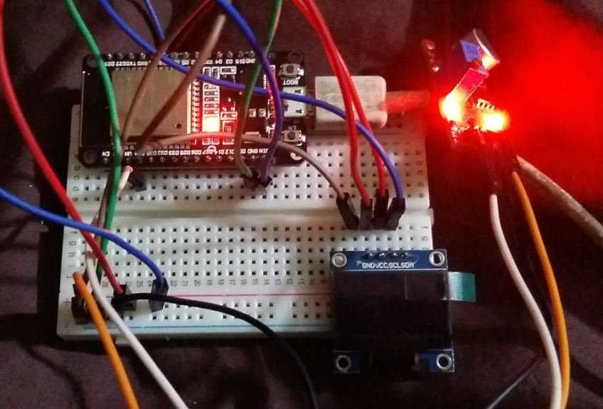
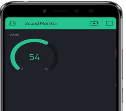
After a few moments, the OLED will start displaying the decibel readings.

Open your Blynk application. Open the project you created and press the ‘play’ button. You will be able to monitor the sound through the gauge.
Other ESP32 Projects:
- ESP32 WebSocket Server using Arduino IDE
- ESP32/ESP8266 Momentary Switch Web Server
- ESP32 Asynchronous Web Server using Arduino IDE
- Telegram ESP32 and ESP8266
- ESP32 Bluetooth Low Energy (BLE) using Arduino IDE
- Displaying Images in ESP32 and ESP8266 Web Server
- Reconnect ESP32 to WIFI after Lost Connection (Solved)
- Use ESP32 Bluetooth Classic with Arduino IDE
- ESP32/ESP8266 Web Server to Control Outputs with a Timer