In this tutorial, we will learn how to use a PICKit3 burner, which is a programmer and debugger system used for programming and developing Microchip PIC microcontrollers. A programmer is a device that transfers and loads the code on microcontrollers like PIC chips. These programmers play an important role, as they allow developers to upload their compiled code into the microcontroller’s memory. This enables the microcontrollers to execute programmed tasks. A microcontroller is non-functional if it is unprogrammable. Hence, a programmer is essential for a developer for programming, testing, and debugging code on the microcontroller.
We have already posted an article on how to use MikroC for PIC and the programming of PIC microcontrollers in C.
PICKit3 Programmer
PICKit3 is a programmer and debugger designed specifically for Microchip PIC microcontrollers. It serves as an interface between the computer and the PIC microcontroller, enabling developers to program the chip, test it, and perform hardware and software debugging tasks. PICKit3 has built-in emulating circuitry and does not require an external debugging chip to simulate the behavior of a PIC chip. This system allows interactive access to all the features of a microcontroller that can be set and modified by using the MPLAB IDE interface. If you are interested in learning more about PIC microcontrollers, you can check out this link: PIC microcontroller tutorials.
PicKit3 Features
The PICkit 3 provides essential features for microcontroller development, such as:
Programming: It allows users to program the firmware or code into PIC microcontrollers’ memory. This is a crucial step in the development process, as it enables the microcontroller to execute the desired instructions and perform specific tasks.
Debugging: PICkit 3 facilitates in-circuit debugging, which means developers can test and monitor the microcontroller’s behavior in real time while it is running within the target circuit. This capability is invaluable for identifying and resolving issues during the development phase.
Target Communication: The PICkit 3 establishes communication between a PC and the target PIC microcontroller through various interfaces, such as ICSP (In-Circuit Serial Programming) or ICD (In-Circuit Debugging).
Breakpoints and Watchpoints: It allows developers to set breakpoints and watchpoints in the code, which pauses the execution at specific points or monitors specific variables or memory locations to aid in debugging.
Firmware Updates: The PICkit 3 can be updated with the latest firmware released by Microchip, providing compatibility with newer microcontroller devices and enhanced features.
The PICkit 3 is widely used by hobbyists, students, and professional embedded systems developers alike due to its user-friendly interface, affordability, and compatibility with a wide range of Microchip’s PIC microcontrollers. It has become an indispensable tool for those working on PIC-based projects and seeking efficient debugging and programming capabilities.
PICKit3 Hardware Components
We have listed Pickit3’s hardware components below.

Lanyard Connection
A useful lanyard connection is provided for placing a strap or a cord to provide ease in carrying the PICKit3.
USB Port Connection
The USB Port connection is based on the USB mini-B connector. It is used to connect the PICkit3 to a PC through a USB cable.
Pin 1 Marker
This marker shows the location of Pin 1 for proper connection with the PICKit3 board on which the PIC chip is placed.
PicKit3 Pinout
This programmer has a six-pin connector, which is used to connect the target device with PICKit3. It consists of the following pins, with pin 1 starting at the marker:
- Vpp/MCLR (Power)
- VDD Target (Power on Target)
- Vss (Ground)
- ICSPDAT/PGD (Standard COM Data)
- ICSPCLK/PGC (Standard COM Clock)
- LVP (Low Voltage Programming)

Status LED
Three LEDs are provided on PICKit3. Different colors indicate different statuses of PICKit3, as follows:
| Status (LED color) | Function of LED |
|---|---|
| Power (Green) | The PICKit3 powered via the USB port. |
| Active (Blue) | PICKit3 is connected to the PC, and the communication link is active. |
| Busy (Yellow) | PICKit3 is busy in performing some functions, such as programming a microcontroller. |
| Error (Red) | The PICKit3 programmer has encountered an issue. |
Push Button
The push button can be used for many tasks, such as starting or stopping the programming process of the microcontroller. It can also be used for resetting the target microcontroller or setting breakpoints during the debugging process.
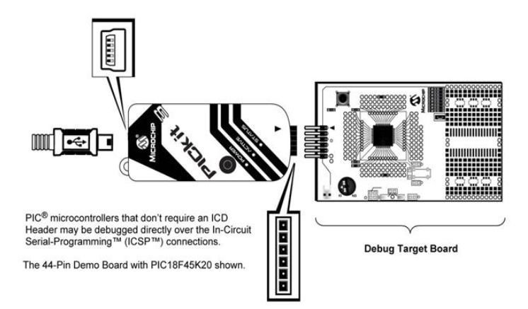
Connection Diagram PICKit3 and PIC Microcontroller
To connect the PICKit3 with PIC microcontrollers, we have provided the pin connections below.
| PICKit3 Pin | PIC Microcontroller pin |
|---|---|
| 1 | 4 |
| 2 | 14 |
| 3 | 5 |
| 4 | 13 |
| 5 | 12 |
| 6 | Not connected |
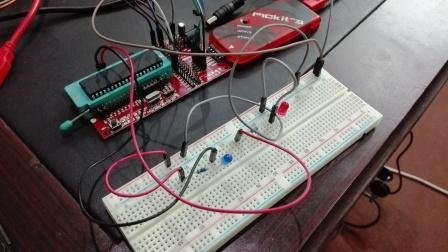
Note: This configuration provided in the table is only for PIC18F1x20. It varies for each microcontroller board. If you are using another board, make sure to consult the datasheet of your respective microcontroller to understand the connections. To connect the PIC18F1x20 microcontroller with the programmer, we have attached the picture above as a reference.
Programmer Board Pinout
The programmer board provides us with six pins on one side for connections with the PICKit3. Following are the pins.
- Vpp/MCLR (Power)
- VDD Target (Power on Target)
- Vss (Ground)
- ICSPDAT/PGD (Standard COM Data)
- ICSPCLK/PGC (Standard COM Clock)
- LVP (Low Voltage Programming)
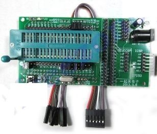
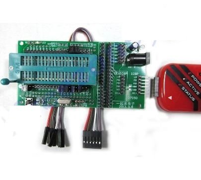
PICKit3 and Programmer Board Connection
Place the chip on the programmer board and then connect it with PICKit3 as shown below. Pickit3 pin counting starts from the arrow marker.
| PICKit3 pin | Programmer board Pin |
|---|---|
| 1 | MCLR |
| 2 | VCC |
| 3 | GND |
| 4 | PGD |
| 5 | PGC |
| 6 | No connection |
Microcontroller and Programmer Board Connection
The following connections are used in the Programmer board and PIC18F46K22.
| Programmer Board pin | PIC18F46K22 Pin |
|---|---|
| MCLR | 1 |
| VCC | 11 |
| GND | 12 |
| PGD | 40 |
| PGC | 39 |
| 6 | No Connection |
Note: These connections are only for PIC18F46K22. For other microcontrollers, consult the data sheet of the respective microcontroller.
Circuit Diagram:
In this section, we have provided a Proteus circuit diagram for a PIC microcontroller.
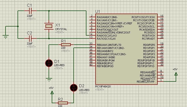
Connect the following circuit as shown above. We don’t need to connect the crystal oscillator and the capacitor. We will just connect LEDs, a power source, and resistors. We will provide connections from the programmer board to the LEDs.
code:
Uploading Code to Pic Microcontroller with PicKit3
- Once all the connections are complete, we will download the MPLAB IDE and install it on our system. We will also install the drivers during this process.
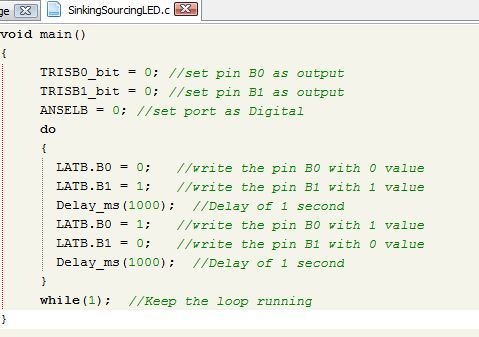
- Now we will start mikroC PRO for the PIC software and write a small program as shown above.
- We will use two LEDs. One in sinking mode and the other in sourcing mode. In sink mode, writing 0 turns the LED off, and writing 1 turns the LED on. Whereas in source mode, Writing 1 turns the LED off, and Writing 0 turns the LED on.
- After completing the program, we will generate the .hex file as explained in tutorial 1.
- Now we will connect the programmer board to the PC through a USB cable.
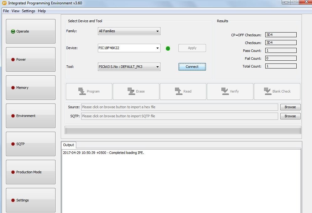
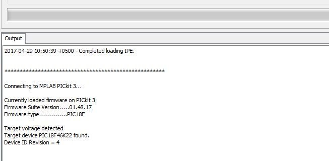
- We will start the MPLAB IDE. An interface similar to the one shown below will open up. Select the microcontroller and then click Connect. Now we will click OK.
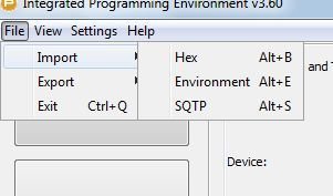
- Go to the file on the menu bar. Click import, then hex.
- Now go to the same folder where you saved the.c file for your MikroC program and open the .hex file.

- After that, click on the program button, and you will see the result in the form of a blinking LED.

Video demo:
Conclusion
In summary:
In this article, we explored the capabilities of the PICKIT3 programmer/debugger. We have seen how to utilize PICKIT3 to effortlessly upload your code into PIC microcontroller. Whether you are a seasoned embedded engineer or a curious hobbyist, this article will serve as your gateway to seamless code uploading and open up new possibilities for your PIC-based projects.
Related Articles
If you liked reading this article, please check out the following links:
I have tried to place a hex-file into a PIC10F200. The code is from Elektor 7/8 2011. The days were much nicer when the computer had a serial port. Is it possible to load a code to a PIC10F200 with a PICkit 3?
Hello Thanks for this Information. on the pickit 3
I want to read an pic12f508 chip and write the contents to a Blank chip of same IC is that possible with the set up that you show on this web page.