Relays are one of the essential components in the electronics industry. A relay is an electromagnet that acts as a switch by opening or closing its contacts to controls the current. Relay modules are typically used with microcontrollers to profoundly control A.C. and D.C. devices, ranging from low voltages to high voltages. We can use relay modules from single to dual to four to eight channels according to the requirement. This tutorial will discuss a 5V dual channel relay module alongside its components, pin configurations, circuit diagram, interfacing, and applications.
5V Dual Channel Relay Module
First, let’s discuss the Components of the 5V dual-channel relay module one by one. The following figure shows the components of a dual-channel relay module.

Relays
As we can see, the module has its specifications written on the blue blocks, which are the relay’s specifications. The name 5V comes from its part number SRD-05VDC-SL-C because it needs only 5V to activate its electromagnet. The maximum current and voltage ratings are 10A and 250VAC and 30VDC per channel, respectively.
Input Block
The right side of the 5V dual channel relay module has the input block shown in the figure. It consists of a control pins block on the upper right corner and a power supply selection jumper on the module’s lower right corner.
Control Pins Block
The control pin block has four pins, i.e., one ground pin, 1 Vcc pin to turn on the module, and two input pins to control respective relays. The Vcc pin also provides power to the status LED, and it should be 5V.
Power Supply Selection Jumper
The name power supply selection inevitably shows that it allows us to choose whether we want to power up our relay module through a microcontroller or an independent power source.
If we want our relays to be energized by a microcontroller, the blue jumper cap should remain intact. In this way, the relay module will be connected physically to the microcontroller. In other words, Vcc and JD-Vcc pins are shorted.
Removal of the jumper cap demands us to provide an independent power source through the JD-Vcc pin to make our relays working. In this way, the microcontroller is no more connected physically to the circuit due to its built-in optoisolators.
Output Block
The left side of the relay module is the output block, which consists of two pairs of three screw terminals, i.e., NO (normally open), C.O. (common), and N.C. (normally closed).
N.C. and NO
They are used to connect the AC/DC load to the relays. NO is, as the name suggests, open by default. When an input signal is applied, it closes the circuit, and load can be controlled, whereas N.C. is vice versa. Normally, NO screw terminal is used unless you want the relay to be purposely off; N.C. is used then.
CO: This screw terminal is to attach the AC/DC power supply to be controlled.
Status LEDs
There are 2 SMD type status LEDs. Each relay has its own status LED, which turns on whenever its respective relay is energized through the input pin. . As it is a 5V dual channel relay module, any voltage more than 5 volts will damage the status LEDs.
Freewheeling Diodes
There are two freewheeling diodes to control the back emf produced by the inductive coils of the relays. Back emf can cause severe damage, so we need freewheeling diodes in order to counter the effect.
Switching Transistors
The relay modules come with switching transistors. More channels, more switching transistors will be placed on the module. The switching transistors’ function is to amplify the current to meet the minimum requirement of the relays. These switching transistors are especially handy to control the relays through any microcontroller like Arduino, ESP32, TM4C123 using its low current general-purpose-input-output pins. The type of transistor determines whether the input pins are active high or active low.
Optoisolators I.C.s
The optoisolator’s true function provides proper isolation between the D.C. Circuit and the power of relays for the transference of the input signal without being directly connected.
5V Dual Channel Relay Module Pinout
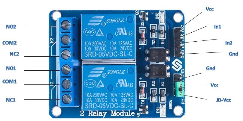
The following figure shows the pinout diagram of dual-channel relay module:

Pin Configuration
Following is the pin configuration of the 5V dual channel relay module.
- Ground pin: It is connected either to the microcontroller’s ground terminal or to the power supply.
- Vcc pin: It is connected to the 5V D.C. supply or to the microcontroller to power the optoisolator and energize the relays, depending on the jumper cap’s condition.
- Input pins: There are two input pins as it is a dual-channel module. They are connected to the digital pins of the microcontroller to give signals to activate the relay to control the loads. These input pins can be active low or active high, and we can provide signals according to the conditions.
- JD-Vcc pin: It is responsible for providing power to the relays as well. If the jumper is intact, it will be shorted to Vcc and powers the electromagnet, but by removing the cap, we can give power separately through an independent source connection for operation.
- NO: Open by default but get connected to COM when the input signal is given to the respective relay.
- CO: It is connected to the load to be controlled.
- NC: Closed or connected to COM by default but gets detached from COM when the input signal is given to the respective relay.
5V Dual Channel Relay Module Internal Circuit Diagram
Moving on from components and pinout, here is the circuit diagram of the dual-channel relay module. The following picture shows the internal circuit diagram of the 5V dual-channel relay module. As you can see, it contains two PC817C based optocouplers. Unlike the 5V single-channel relay module, we can provide a separate power supply to the optoisolator and relay input. In this way, we can isolate the microcontroller, which drives a relay, from the high voltage side.

To provide a separate power supply to the relay coil and optoisolator, we use the JD-VCC jumper. If the jumper is connected, both the optocoupler and relay coil will be powered from the same power source. Otherwise, if not connected, we can power them with separate power sources. Vcc and JD-Vcc are not shorted, and we will need an independent power source for relays working and will be connected at JD-Vcc pin.
The relays energize using the digital output signal from a microcontroller. It should be noted that an NPN transistor is used in this dual-channel relay module. Hence, the relay activation current will only flow through the coil only when we apply an active low to the input pin of the relay module. It will turn on the optoisolators and power the relays for its functioning.
5V Dual Channel Relay Module Proteus Simulation
The following circuit shows the proteus simulation for one of the relay module. In this example, we power both the relay coil and optocoupler through the same power supply. As you can see, as soon as we apply a logic low signal to the input pin of PC817C, the relay activates, and the lamp turns on. Similarly, on a logic high input signal, the relay remains deactivated, and the light remains off.

5V Dual Channel Relay Module Interfacing with Arduino
Now you know everything about the 5V dual channel relay module. It’s time to do a real project with this module. In this section, we will learn to interface the dual-channel relay module with Arduino. We will use only one channel for demonstration purposes.
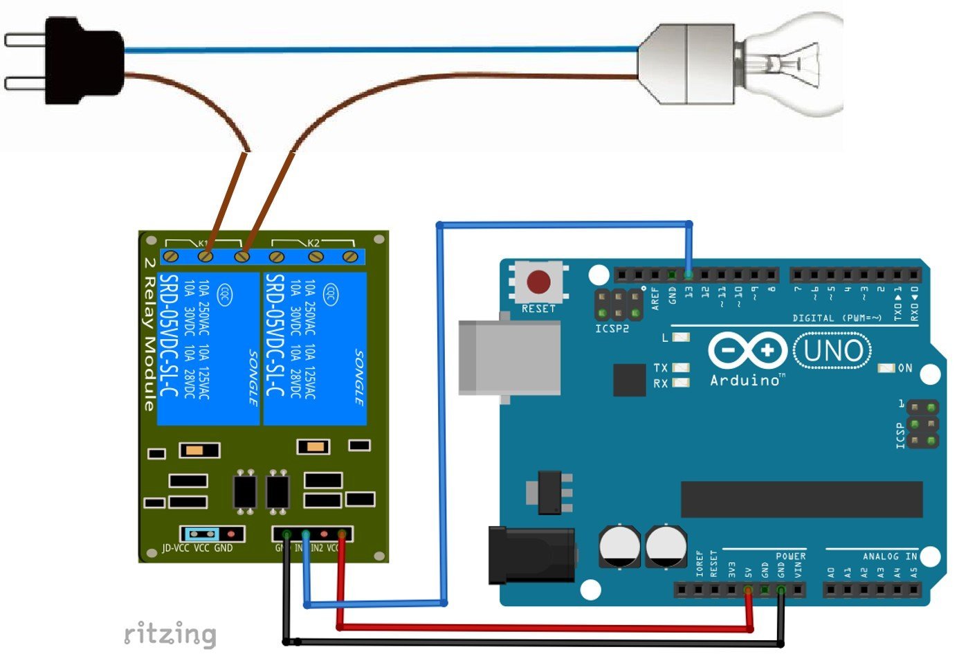
Now make connections with the module and Arduino Uno according to this circuit diagram.
In this circuit, we power the optocoupler and relay coil from the same power source from Arduino. Hence, we placed the jumper. But if you want to power from separate power sources, you should remove the jumper and connect it with JD-Vcc and the ground terminal of the dual-channel relay module.

| Relay Module | Arduino Uno |
|---|---|
| IN1 | D13 |
| GND | GND |
| VCC | 5V |
Moreover, the load is connected with a channel-one of the relay module under normally open settings. That means when a relay is active, the lamp will also become active, and under normal conditions, the lamp remains off because the load is connected with an AC power supply through a normally closed terminal.
Arduno Code
This Arduino example code turns on the relay for two seconds and then turns off for 2 seconds.
//the relays connect to
int IN1 = 13;

#define ON   0
#define OFF  1
void setup()
{
  relay_init();//initialize the relay
}

void loop() {
  relay_SetStatus(ON);//turn on RELAY_1
  delay(2000);//delay 2s
  relay_SetStatus(OFF);//turn off RELAY_1
  delay(2000);//delay 2s
}
void relay_init(void)//initialize the relay
{
  //set all the relays OUTPUT
  pinMode(IN1, OUTPUT);
  relay_SetStatus(OFF); //turn off all the relay
}
//set the status of relays
void relay_SetStatus( unsigned char status_1)
{
  digitalWrite(IN1, status_1);

}
Applications
- Controlling high A.C. voltages
- Automation systems
- Motor speed control from start-delta converters
- Electric isolation between low and high voltages
Related Relay Tutorials:
- 5V Single Channel Relay Module
- ESP32 web server control relay and 220 volt lamp
- INTRODUCTION TO ULN2803 – relay driver IC
- Relay Module interfacing with pic16f877a microcontroller
- Microcontroller interfacing to relays using ULN2003
- Three Phase Solid State Relay with ZVS using pic microcontroller
- Relay Module interfacing with arduino
- Electromechanical Relays interfacing with microcontrollers
- Relay working and types

