In this comprehensive user guide, we will learn to interface a rotary encoder module with Arduino. We will discuss about the working of rotary encoders, its pinout, and its connection with Arduino. With the help of two sketches, we will show you two different ways to read the rotary encoders. They will focus on how to use the rotary encoder to monitor the direction of rotation. Additionally, we will also show you how to control a servo motor through the rotary encoder module.
Introducting Rotary Encoders
A rotary encoder is such a type of encoder which is used for measuring the angular position of any rotating shaft. It determines the amount and the type of rotation. It generates an analog or digital signal depending on the rotational movement. These can be used to control the brightness of the LED, controlling the servos, and many other things. The rotary encoder has no start, middle, or end, so you can rotate it as much as you want.
On many rotary encoders, when you will move it, you will feel a bump. These are known as steps. Most have 12 steps, but they can be up to 200. There are many types of rotary encoders available which are either classified as the output signal or the sensing technology. The one we are using is the output rotary encoder and it is the simplest one.
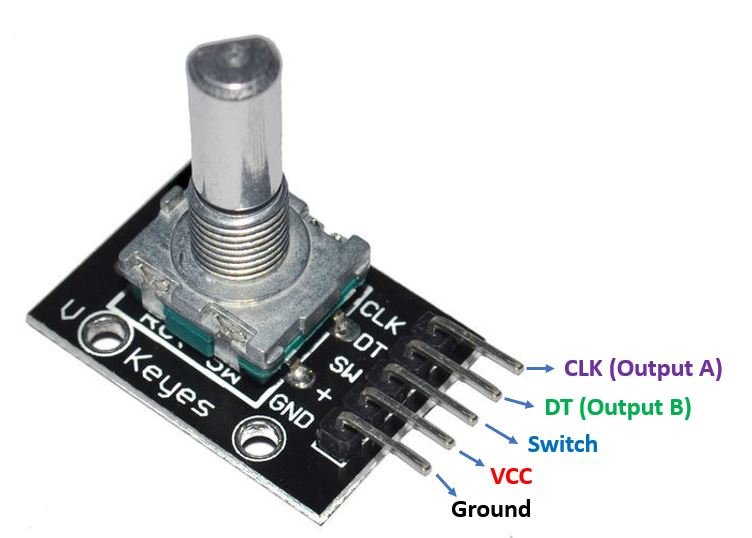
A simple rotary encoder module is shown below:

How Rotary Encoders Work?
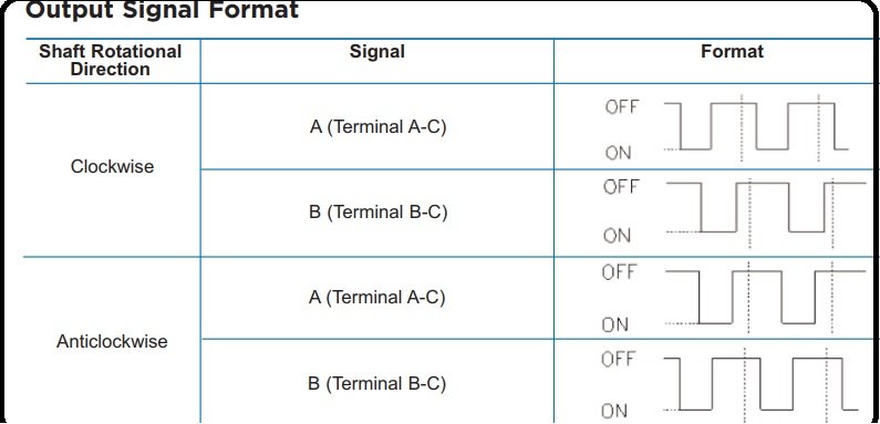
The rotary encoder gives us two square waves output (A and B) which are 90 degrees out of phase which each other. The number of pulses completed each turn varies. We read the value of pulse B when every time A signal pulse goes from positive to zero. When the encoder is turned clockwise, B pulse is positive and when the encoder is turned counter-clockwise, the B pulse is negative. So, we can determine the direction of turn by checking both outputs with micro-controller and by counting the number of A pulses. We can also determine the speed by counting the frequency of pulses. So, you can see that it has a lot of advantages and it is much more applications than a simple potentiometer.
Pin out
Rotary encoder module consists of five pins such as CLK, DT, SW, + and GND.
- The GND pin is connected to ground and positive voltages are applied at + pin. These voltages should be with in the range of 3.3 volts to 5 volts for normal working of this encoder.
- The SW is the switch pin that gives the output of the active low push button switch. When we push the knob of the rotary encoder from the top, the voltage goes LOW. The rotary encoder thus also acts as a push button.
- The CLK pin gives the main output pulse which is used to determine the rotation. Its output goes from HIGH to LOW (one cycle) whenever the knob of the rotary encoded is rotated by one click.
- The DT pin is also used to determine the rotation but lags the DLK by 90 degree phase shift.
- Two light emitting diodes (LEDs) are connected at pins CLK and DT with the help of two 220 ohms resistor which are connected in series with these light emitting diodes. CLK and DT pins produce square waves which are 90 degree out of phase with each other and these two square waves are used to measure clock wise and anti clock wise rotation of shaft.
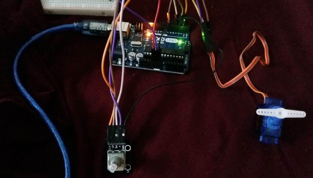
Interfacing Rotary Encoder with Arduino
As we have seen above, the rotary encoder module has 5 terminals which we will connect with the Arduino board. As the rotary encoder module requires an operating voltage in the range of 3.3-5V hence we will connect the VCC terminal with 5V which will be in common with the Arduino board. The CLK, DT and SW pins will be connected with any digital input pins of the Arduino board.
The connections between the two devices can be seen below.
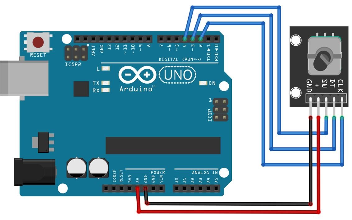
We have used GPIO4 to connect with the SW pin, GPIO3 to connect with the DT pin and GPIO2 to connect with the CLK pin. Additionally, the VCC and GND pins are connected with the Arduino’s 5V and GND pins respectively.
Arduino Sketch: Reading Rotary Encoders
Open your Arduino IDE and go to File > New. A new file will open. Copy the code given below in that file and save it.
This sketch will determine the amount and type of rotation. Moreover, we will also be able to tell whether the push button was pressed or not.
#define CLK 2
#define DT 3
#define SW 4

int count = 0;
int current_stateCLK;
int last_stateCLK;
String current_direction ="";
unsigned long last_press = 0;

void setup() {
  pinMode(CLK,INPUT);
  pinMode(DT,INPUT);
  pinMode(SW, INPUT_PULLUP);

  Serial.begin(115200);

  last_stateCLK = digitalRead(CLK);
}

void loop() {

  current_stateCLK = digitalRead(CLK);
  if (current_stateCLK != last_stateCLK  && current_stateCLK == 1){
    if (digitalRead(DT) != current_stateCLK) {
      count --;
      current_direction ="Anti-Clockwise";
    } else {
      count ++;
      current_direction ="Clockwise";
    }

    Serial.print("Direction: ");
    Serial.print(current_direction);
    Serial.print(" | Count: ");
    Serial.println(count);
  }

  last_stateCLK = current_stateCLK;

  int button_state = digitalRead(SW);
  if (button_state == LOW) {
    if (millis() - last_press > 50) {
      Serial.println("Button pressed!");
    }
    last_press = millis();
  }
  delay(1);
}
How the Code Works?
Firstly, we will define the rotary encoder CLK, DT and SW pins that we will connect with the Arduino UNO. They are GPIO pins 2, 3 and 4 respectively for CLK, DT and SW.
#define CLK 2
#define DT 3
#define SW 4
Next, we will define some variables which we will be used later on in the sketch. The ‘count’ variable monitors the number of times the knob of the rotary encoder is rotated which will be after every click. The ‘current_stateCLK’ and ‘last_stateCLK’ will be used to monitor the state of the CLK output. This will play an integral role in determining the amount of the rotation. The ‘current_direction’ is a string variable that will store the type of rotation ‘Clockwise’ or Anti-Clockwise.’ Initially it is an empty string. Lastly, the ‘last_press’ variable will be used to debounce the switch.
int count = 0;
int current_stateCLK;
int last_stateCLK;
String current_direction ="";
unsigned long last_press = 0;
setup()
Inside the setup() function, we will open a serial connection at a baud rate of 115200.
Serial.begin(115200);
The pinMode() function will set up the CLK and DT pins as input pins and the SW pin as an input with the internal pull-up resistor enabled.
  pinMode(CLK,INPUT);
  pinMode(DT,INPUT);
  pinMode(SW, INPUT_PULLUP);
Then, we will obtain the value from the CLK pin and store it in the variable ‘last_stateCLK’ by using the digitalRead() function.
last_stateCLK = digitalRead(CLK);loop()
Inside the loop() function, we will first read the value from the CLK pin and store it in the ‘current_stateCLK’ variable. Then by using an if statement we will check if current state of the CLK pin is 1 (meaning a single state change occurred) and does not match the last state (meaning the knob was rotated). Now inside the second if statement we will check the type of rotation. This will be checked while comparing the current state of the CLK pin with that of the value DT pin. If both of these values do not match then it means that the knob was rotated in anti-clockwise direction. Otherwise, the knob was rotated in the clockwise direction. The ‘current_direction’ variable will be set accordingly. Moreover, we will increment the count variable for the clockwise rotation and decrement the count variable for the anti-clockwise rotation.
The direction of rotation with the count value will be displayed on the serial monitor.
  current_stateCLK = digitalRead(CLK);
  if (current_stateCLK != last_stateCLK  && current_stateCLK == 1){
    if (digitalRead(DT) != current_stateCLK) {
      count --;
      current_direction ="Anti-Clockwise";
    } else {
      count ++;
      current_direction ="Clockwise";
    }

    Serial.print("Direction: ");
    Serial.print(current_direction);
    Serial.print(" | Count: ");
    Serial.println(count);
  }
We will set up the last state of the CLK pin to the current state of the CLK pin.
last_stateCLK = current_stateCLK;Next, we will read the value of the switch pin and save it in the integer variable ‘button_state.’ Now to monitor that whether the push button was pressed or not we will check if the button_state variable is LOW and additionally it has been LOW for more than 50 milliseconds then we will print ‘Button pressed!’ on the serial monitor. In this manner, the debounce the psuh button.
  int button_state = digitalRead(SW);
  if (button_state == LOW) {
    if (millis() - last_press > 50) {
      Serial.println("Button pressed!");
    }
    last_press = millis();
  }
  delay(1);
Demonstration
To see the demonstration of the above code, upload the code to Arduino. Before uploading the code, make sure to select Arduino UNO from Tools > Board.

Also, select the correct COM port to which the Arduino board is connected from Tools > Port.
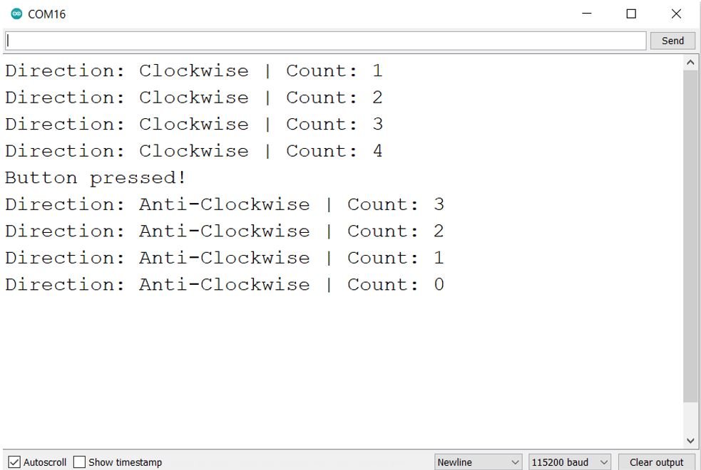
Once the code is uploaded to your board, open your serial monitor and set the baud rate to 115200. Now rotate the knob of the rotary encoder. First, we have rotated the knob 4 clicks in the clockwise direction. Then we pushed the push button. Next, we rotated the knob 4 clicks in the anti-clockwise direction.
Reading Rotary Encoders using Interrupts
Now let us look at another method to read the rotary encoder. Notice that we need to constantly note the states of both the CLK pin and the DT pin in order to read the rotary encoder. In the previous sketch, we used a continuous polling event to check up on the states. That, however was not an efficient way of reading the rotary encoder due to many factors. We will show you another better way to monitor the states of the CLK and DT pin and this will be through using interrupts. By using interrupts, we will be able to efficiently carry out the process of reading the rotary encoder values.
To use the interrupts feature to monitor the states of the CLK and DT pin we will have to make sure these two pins are connected with the external interrupt pins of the Arduino UNO. Arduino UNO features external interrupt on two digital pins. GPIO2 and GPIO3.
Follow the schematic diagram below:

Notice that we have not connected the SW pin of the rotary encoder module with Arduino UNO. This is because the Arduino board only consists of two external interrupts: ext int 1 and ext int 2. Each of which we have connected with the CLK and DT pins.
Arduino Sketch
Open your Arduino IDE and go to File > New. A new file will open. Copy the code given below in that file and save it.
This sketch will determine the amount and type of rotation. However, we will not be able to tell whether the push button was pressed or not because the Arduino board only consists of two external interrupts thus we will not be able to monitor the state of the SW pin.
#define CLK 2
#define DT 3

int count = 0;
int current_stateCLK;
int last_stateCLK;
String current_direction ="";

void setup() {
  pinMode(CLK,INPUT);
  pinMode(DT,INPUT);

  Serial.begin(115200);
  last_stateCLK = digitalRead(CLK);
  attachInterrupt(0, updateEncoder, CHANGE);
  attachInterrupt(1, updateEncoder, CHANGE);
}

void loop() {
}

void updateEncoder(){
  current_stateCLK = digitalRead(CLK);
  if (current_stateCLK != last_stateCLK  && current_stateCLK == 1){

    if (digitalRead(DT) != current_stateCLK) {
      count --;
      current_direction ="Anti-Clockwise";
    } else {
      count ++;
      current_direction ="Clockwise";
    }

    Serial.print("Direction: ");
    Serial.print(current_direction);
    Serial.print(" | count: ");
    Serial.println(count);
  }
  last_stateCLK = current_stateCLK;
}
How the Code Works?
Most of the code is similar as that of the previous sketch. We will explain the parts where the interrupts feature is being used.
Inside the setup() function, we will first configure the CLK an DT pins as input pins. Then we will attach the interrupts to these pins. For Arduino UNO, GPIO2 and GPIO3 are the interrupt pins. GPIO2 which is connected with CLK corresponds to external interrupt 0 and GPIO3 which we have connected to DLK corresponds to external interrupt 1. Now when we rotate the knob of the rotary encoder the voltage goes through a change of either HIGH-LOW or LOW-HIGH. The interrupt monitors this change on the two external interrupt pins. Whenever a change will occur, the interrupt service routine(ISR) will be called. In this case the ISR is updateEncoder.
void setup() {
  pinMode(CLK,INPUT);
  pinMode(DT,INPUT);

  Serial.begin(115200);
  last_stateCLK = digitalRead(CLK);
  attachInterrupt(0, updateEncoder, CHANGE);
  attachInterrupt(1, updateEncoder, CHANGE);
}
The updateEncoder() function will be called whenever the interrupt will be triggered on either of the two pins. Notice that this function determines the type of rotation and increments/decrements the count variable accordingly.
void updateEncoder(){
  current_stateCLK = digitalRead(CLK);
  if (current_stateCLK != last_stateCLK  && current_stateCLK == 1){

    if (digitalRead(DT) != current_stateCLK) {
      count --;
      current_direction ="Anti-Clockwise";
    } else {
      count ++;
      current_direction ="Clockwise";
    }

    Serial.print("Direction: ");
    Serial.print(current_direction);
    Serial.print(" | count: ");
    Serial.println(count);
  }
  last_stateCLK = current_stateCLK;
}
Controlling Servo Motor using Rotary Encoder Module
As discussed earlier, rotary encoders are very useful. Let us show you one application of the rotary encoder where we will use it to control a SG-90 servo motor.
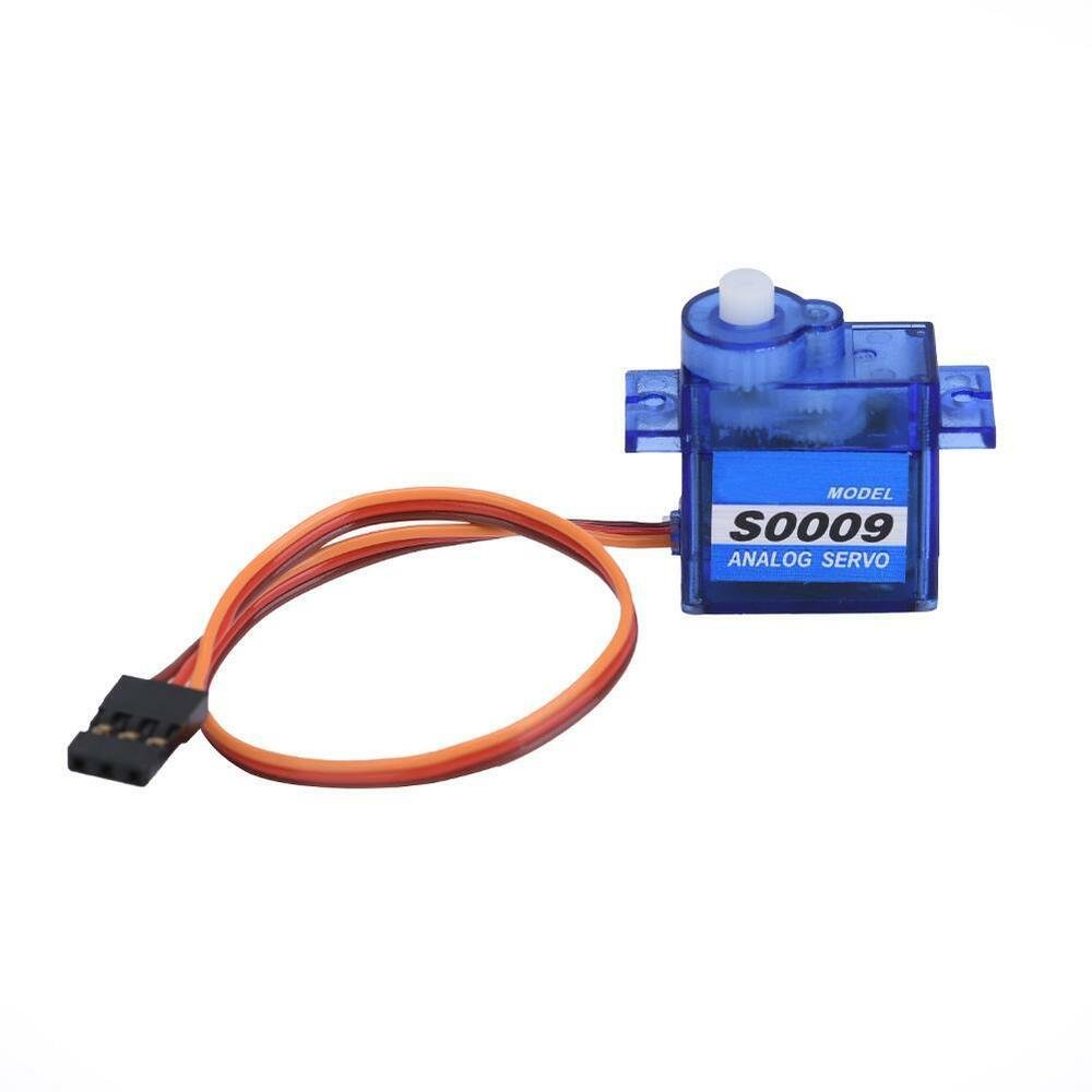
SG-90 Servo Motor
SG90 is a low cost and high output power servo motor. It can rotate up to 180 degrees and each step can be of maximum 90 degrees. Moreover, it is small enough that it can easily fit into your robotics ARM or obstacle avoidance robotics projects. On top of that, it requires only one output pulse signal to control its movement.
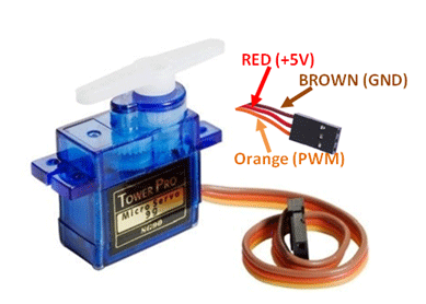
The following figure shows the pinout diagram of SG90 servo motor. It consists of three pins only such as PWM, ground and Vcc pin. Brown, orange and red wires are GND, Vcc and PWM pins respectively. Details and functionality of each pin is listed in the next section.
Pin Configuration Details
Vcc and ground, as their name suggests, are the power supply pins which are used to power servo motor. Only 5 volts of power signal is required to power this motor. Mostly microcontrollers or development boards have onboard 5 volts supply which we can use to power SG90 servos.
This table briefly describes all three pins:
| Wire of motor | Possible colors of each wire |
|---|---|
| Vcc pin | Red |
| GND pin | Black, or brown |
| Control Signal / PWM pin | Yellow, orange, or white |
Interfacing Rotary Encoder Module with Arduino UNO and SG-90 servo motor
The following schematic diagram shows the connections between the three devices.
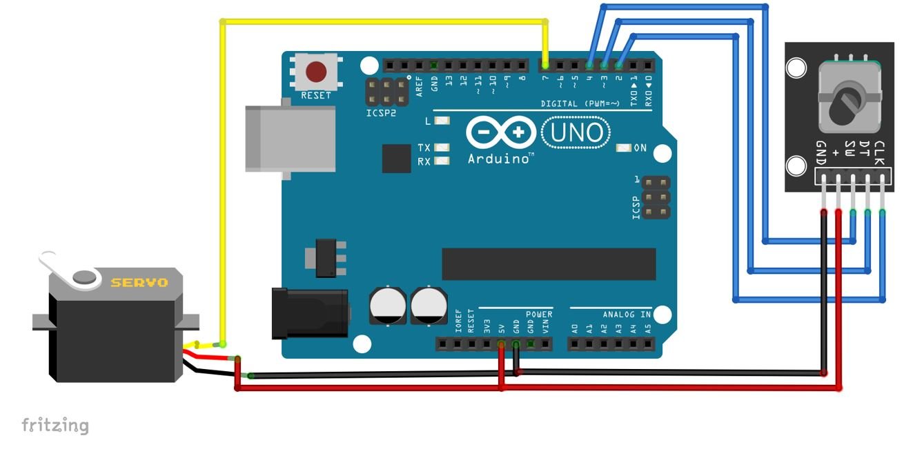
Notice that we have connected the rotary encoder with the Arduino UNO at the same pins as used in the first sketch. For the servo motor, we have connected the control signal pin with GPIO7. You can use any suitable digital pin of Arduino UNO. The VCC and GND pins are in common with the Arduino UNO and the rotary encoder module. You can however, use an external 5V power supply to power the servo motor as well.
Arduino Sketch: Controlling Servo Motor using Rotary Encoder Module
Open your Arduino IDE and go to File > New. A new file will open. Copy the code given below in that file and save it.
This sketch will control the SG-90 servo motor using the rotary encoder module by moving the arm of the motor by one degree whenever the knob of the rotary encoder will be rotated by one click.
#include <Servo.h>

#define CLK 2
#define DT 3

Servo servo;
int count = 0;
int current_stateCLK;
int last_stateCLK;

void setup() {
  pinMode(CLK,INPUT);
  pinMode(DT,INPUT);

  Serial.begin(115200);

  servo.attach(7);
  servo.write(count);
  last_stateCLK = digitalRead(CLK);
}

void loop() {
  current_stateCLK = digitalRead(CLK);
  if (current_stateCLK != last_stateCLK  && current_stateCLK == 1){

    if (digitalRead(DT) != current_stateCLK) {
      count --;
      if (count<0)
        count=0;
    } else {
      count ++;
      if (count>179)
        count=179;
    }
    servo.write(count);
    Serial.print("Position: ");
    Serial.println(count);
  }

  last_stateCLK = current_stateCLK;
}
How the Code Works?
Firstly we will include the Servo.h library.
#include <Servo.h>Then we will define the rotary encoder CLK and DT pins that we will connect with the Arduino UNO. They are GPIO pins 2 and 3 respectively for CLK and DT.
#define CLK 2
#define DT 3
Then we will create an object of this library called ‘servo.’
Servo servo;Next, we will define some variables which we will be used later on in the sketch. The ‘count’ variable monitors the number of times the knob of the rotary encoder is rotated which will be after every click. The ‘current_stateCLK’ and ‘last_stateCLK’ will be used to monitor the state of the CLK output.
int count = 0;
int current_stateCLK;
int last_stateCLK;
setup()
Inside the setup() function, we will first configure the CLK an DT pins as input pins. Then we will attach GPIO 7 with the servo object. Notice this is the GPIO pin we have connected with the Control Signal pin of the servo motor. Then by using the write() method on the servo object, we will pass the ‘count’ variable inside it. This will be used to change the position of the servo arm according to the count.
void setup() {
  pinMode(CLK,INPUT);
  pinMode(DT,INPUT);

  Serial.begin(115200);

  servo.attach(7);
  servo.write(count);
  last_stateCLK = digitalRead(CLK);
}
loop()
Inside the loop() function, we will first read the value from the CLK pin and store it in the ‘current_stateCLK’ variable. Then by using an if statement we will check if current state of the CLK pin is 1 (meaning a single state change occurred) and does not match the last state (meaning the knob was rotated).
Now inside the second if statement we will check the type of rotation. This will be checked while comparing the current state of the CLK pin with that of the value DT pin. If both of these values do not match then it means that the knob was rotated in anti-clockwise direction. Otherwise, the knob was rotated in the clockwise direction. The ‘count’ variable will be decremented for anti-clockwise rotation and incremented for clockwise rotation. For anti-clockwise rotation while decrementing the count if it reaches a negative number hen we will set the ‘count’ variable to 0. Similarly, for clockwise rotation while incrementing the count, if it reaches greater than 179 then we will set the ‘count’ variable to 179. This is because the servo motor accepts values between 0-179.
The ‘count’ variable will be passed a parameter inside the write() method. This will position the servo arm according to the number of rotation.
Lastly, we will set up the last state of the CLK pin to the current state of the CLK pin and the loop continues.
void loop() {
  current_stateCLK = digitalRead(CLK);
  if (current_stateCLK != last_stateCLK  && current_stateCLK == 1){

    if (digitalRead(DT) != current_stateCLK) {
      count --;
      if (count<0)
        count=0;
    } else {
      count ++;
      if (count>179)
        count=179;
    }
    servo.write(count);
    Serial.print("Position: ");
    Serial.println(count);
  }

  last_stateCLK = current_stateCLK;
}
Demonstration
To see the demonstration of the above code, upload the code to Arduino. But, before uploading code, make sure to select the Arduino board from Tools > Board and also select the correct COM port to which the Arduino board is connected from Tools > Port.
Once the code is uploaded to Arduino, move the knob of the rotary encoder one click at a time in the clockwise or anti-clockwise direction. The servo arm will start moving in that direction by one degree.
You can watch the demonstration below:
Here we have rotated the knob faster in order to show the clear movement of the servo motor’s arms.
Control LED Brightness with Rotary Encoder and Arduino
In this section, we will see how to control LED brightness using rotary and Arduino. We will use Arduino Mega in this example. Make connection with Arduino Mega, Rotary encoder, and LED according to a schematic diagram shown below:
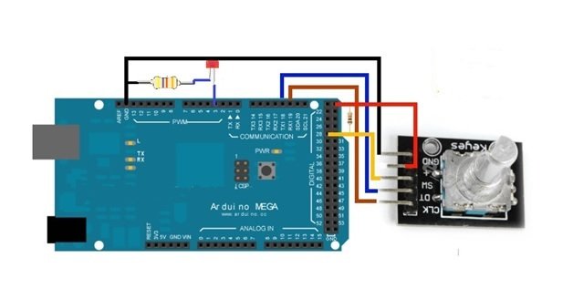
First of all, connect the 5V and the GND of the encoder with the 5V and GND of the Arduino mega. Then connect the encoder pin A and Encoder pin B which are CLK and DT to the Arduino mega’s pin 19 and 18, respectively. Then connect the encoder push button pin (SW) to the Arduino pin 28. At last, we have to connect the led whose brightness we will control. Connect the positive side of led to the pin 3 of Arduino and the negative side to the ground of Arduino. So, when we will move the rotary encoder in one direction, then the brightness of the led will increase and when we will use it in another direction then the brightness of the led will decrease. This is the simplest example in which we can use it. However, we can also control the motor and many other things using it.
Arduino Sketch
This code is for the rotary encoder to control the brightness of led
int brightness = 120 ;                                       // how much led will be bright at start

int fadeAmount = 10 ;

unsigned long currentTime ;

unsigned long loopTime ;

const int pin_A = 19;                                  // initializing pin 19 for encoder pin A

const int pin_B = 18;                               // initializing pin 18 for encoder pin B

int pushbutton = 28;                               // initializing pin 28 for push button.

unsigned char encoder_A;

unsigned char encoder_B;

unsigned char encoder_A_prev=0;

void setup ( )  {

  pinMode ( 3 , OUTPUT ) ;                       // declaring pin 3 as output for the led

  pinMode ( pin_A , INPUT ) ;                    // declaring pin 19 as input

  pinMode ( pin_B , INPUT ) ;                   // declaring pin 18 as input

  currentTime = millis ( ) ;

  loopTime = currentTime ;

}

void loop ( )  {

  currentTime = millis ( ) ;                           // This command will get the current elapsed time

  if ( currentTime >= ( loopTime + 5 ) ){              // 5ms since last check of encoder = 200Hz


    encoder_A = digitalRead ( pin_A ) ;                 // Reading the encoder pins

    encoder_B = digitalRead ( pin_B ) ;                 // Reading the encoder pins

    if ( ( !encoder_A ) && ( encoder_A_prev ) ) {

      // A has gone from high to low

      If ( encoder_B )  {                                  // encoder is moved clock wised so B is high

        If ( brightness + fadeAmount <= 255 ) brightness += fadeAmount ;    // This command will increase the brightness

      }

      else {

        // if encoder is moved counter-clockwise then b will be low

        If ( brightness - fadeAmount >= 0 ) brightness -= fadeAmount ;       // This will decrease the brightness

      }

    }

    encoder_A_prev = encoder_A ;                                                                            // this will Store value of A for next time

    analogWrite ( 3, brightness ) ;                                                                                  // This will set the brightness of pin 3:

    loopTime = currentTime ;

  }

}
Control DC Motor using Rotary Encoder and Arduino
In this section, we will see how to control DC motor using rotary and Arduino. We will use Arduino Uno in this example. Make connection with Arduino Mega, Rotary encoder, and a DC motor according to a schematic diagram shown below:
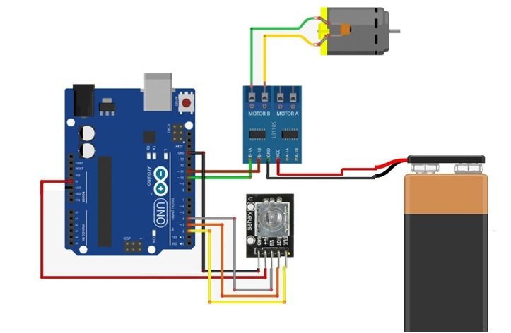
In this tutorial, we are going to control a dc motor using the rotary encoder. To power a motor we will use a 9V power supply and an L91105 motor controller.
Arduino Sketch
volatile boolean Turnfound;                        // initializing a Boolean turn

volatile boolean up;                             // initializing a Boolean for speed up

const int CLK=2;   // initializng a const int for clock signal

const int DT=3;    // initializng a const int for Reading DT signal

const int SW=4;    // initializng a const int for Reading Push Button switch


// Connections for L9110 motor controller

#define L9110_B_IA 10                                        // initializing pins for motor

#define L9110_B_IB 11

// Motor Speed & Direction

#define MOTOR_SPEED L9110_B_IA                                       // Motor PWM Speed

#define MOTOR_DIRECTION L9110_B_IB                                              // Motor Direction
// Interrupt routine runs if CLK goes from HIGH to LOW

void isr ()  {

delay(4);                                                                                              // giving a delay

if (digitalRead(CLK))                                                                        // reading the clock signal

  up = digitalRead(DT);

else

   up = !digitalRead(DT);

Turnfound = true;

}


void setup ()  {

pinMode(CLK,INPUT);                                // initializing clk pin as input

pinMode(DT,INPUT);                                 // initializing DT pin as input

pinMode(SW,INPUT);                                // initializing SW pin as input

digitalWrite(SW, HIGH);                           // Pull-Up resistor for switch

attachInterrupt (0,isr,FALLING);

Serial.begin (9600);                             // Setting baud rate at 9600

Serial.println("Start");

pinMode( MOTOR_DIRECTION, OUTPUT );

pinMode( MOTOR_SPEED, OUTPUT );

digitalWrite( MOTOR_DIRECTION, LOW );       // This will Set motor to off

digitalWrite( MOTOR_SPEED, LOW );

}


void loop ()  {

static long RotaryPosition=0;

if (!(digitalRead(SW))) {

   if (RotaryPosition == 0)

   } else {

       RotaryPosition=0;

       digitalWrite( MOTOR_DIRECTION, LOW );                        //This will turn motor off

       analogWrite( MOTOR_SPEED, LOW );

       Serial.print ("Reset = ");

       Serial.println (RotaryPosition);

   }

}

// Runs if rotation was detected

if (Turnfound)  {

   if (up) {

     if (RotaryPosition >= 100) { // Max value set to 100

       RotaryPosition = 100;

     }else {

         RotaryPosition=RotaryPosition+2;}

   }else {

     if (RotaryPosition <= -100) { // Max value set to -100

       RotaryPosition = -100;}

       else {

         RotaryPosition=RotaryPosition-2;}}

   Turnfound = false;  // do NOT repeat IF loop until new rotation detected

   Serial.print ("Speed = ");

   Serial.println (RotaryPosition);        // if Rotation is Clockwise

   if (RotaryPosition > 0 && RotaryPosition < 11) {

       digitalWrite( MOTOR_DIRECTION, LOW );                                                      //This will turn off the motor

       analogWrite( MOTOR_SPEED, LOW );

   }

   if (RotaryPosition > 10 && RotaryPosition < 21) {

     digitalWrite( MOTOR_DIRECTION, HIGH );                                                       // direction will be forward

     analogWrite( MOTOR_SPEED, 180 );                                   // PWM speed will be 180

   }


   if (RotaryPosition > 50 && RotaryPosition < 61) {

     digitalWrite( MOTOR_DIRECTION, HIGH );                                                       // direction will be forward

     analogWrite( MOTOR_SPEED, 100 );                                   // PWM speed will be 100

   }

   if (RotaryPosition > 90) {

     digitalWrite( MOTOR_DIRECTION, HIGH );                                                       // direction will be forward

     analogWrite( MOTOR_SPEED, 20 );                                                     // PWM speed will be 20

   }


// if Rotation is Counter-Clockwise


   if (RotaryPosition < 0 && RotaryPosition > -11) {

       digitalWrite( MOTOR_DIRECTION, LOW );                                                      // This will turn off the motor

       analogWrite( MOTOR_SPEED, LOW );

   }

   if (RotaryPosition < -10 && RotaryPosition > -21) {

     digitalWrite( MOTOR_DIRECTION, LOW );                                                        // direction will be reverse

     analogWrite( MOTOR_SPEED, 40 );                                                     // PWM speed will be 40

   }

   if (RotaryPosition < -40 && RotaryPosition > -51) {

     digitalWrite( MOTOR_DIRECTION, LOW );                                                        // direction will be reverse

     analogWrite( MOTOR_SPEED, 100 );                                   // PWM speed will be 100

   }

   if (RotaryPosition < -80 && RotaryPosition > -91) {

     digitalWrite( MOTOR_DIRECTION, LOW );                                        // direction will be reverse

     analogWrite( MOTOR_SPEED, 180 );                   // PWM speed will be 180

   }

   if (RotaryPosition < -90) {

     digitalWrite( MOTOR_DIRECTION, LOW );                                        // direction will be reverse

     analogWrite( MOTOR_SPEED, 200 );                   // PWM speed will be 200

   }

}}
For more Rotary Encoders Articles follow the links below: