In this tutorial, we will learn to generate PWM using Arduino. We will learn to generate fixed frequency, variable frequency, fixed duty cycle, and variable duty cycle PWM signal using Arduino.
PWM Introduction
PWM stands for Pulse Width Modulation. From its name, it is clear that in this technique the width of pulses of a waveform is controllable (changes). This means for how much time a pulse is in the HIGH state or in the LOW state from a given time is controllable.
In this technique, we use digital means to get an analog result. Digital control is used to create a square waveform by switching a signal ON and OFF repeatedly. This ON and OFF pattern generate full VCC voltage at the ON position and 0V at the OFF position.
The duty cycle is defined as the average ON time of a pulse divided by the TOTAL time of the pulse, so basically in PWM, the duty cycle of pulses is changed.
For more information on PWM pins of Arduino, read this in-depth article:
What is Pulse Width Modulation
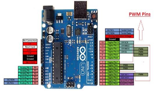
Arduino PWM Pins
There are 6 PWM pins available on the Arduino UNO board and the Pins number are 3, 5, 6, 9, 10, 11. The number of PWM pins vary from one Arduino board to another Arduino Board. The following table shows the PWM pins for Arduino Uno, Arduino Mini, Arduino Nano, and Arduino Mega. It also lists the default PWM frequency of each pin.
| Board | Pins | Freqeuncy |
|---|---|---|
| Arduino_Uno | 3, 5, 6, 9, 10, 11 | 490 Hz (pins 5 and 6: 980 Hz) |
| Arduino_Nano | 3, 5, 6, 9, 10, 11 | 490 Hz (pins 5 and 6: 980 Hz) |
| Arduino_Mini | 3, 5, 6, 9, 10, 11 | 490 Hz (pins 5 and 6: 980 Hz) |
| Arduino Mega | 2 to 13, 44 to 46 | 490 Hz (pins 3 and 11: 980 Hz) |
In this tutorial, we will use the Arduino Uno. But the overall concepts to generate PWM remains valid for other Arduino boards also.
The following figure shows these pins on Arduino UNO Board.
Arduino AnalogWrite() PWM Function
The analogWrite() function which is available by default in Arduino IDE is used to generate a PWM signal. The function can generate PWM with the default frequency of each pin as mentioned in the above table. At each of these pins, a PWM waveform of fix frequency can be generated using the analogWrite() command.
The first argument to analogWrite() is a pin number from which we want to get PWM signal. The second argument is a duty cycle. The duty cycle can vary between 0 to 255 which maps to 0 to 100% duty cycle in percentage.
By default, the waveform of the following frequency is generated by Arduino pins when called using the analogWrite() command.
- The frequency at Pin 5 and Pin 6 is 980Hz.
- The frequency at pin9, pin10, pin11, and pin3 is 490Hz.
Fix Frequency PWM Arduino
In this section, let’s discuss to generate a fixed frequency PWM using the D3 pin of Arduino Uno.
Code
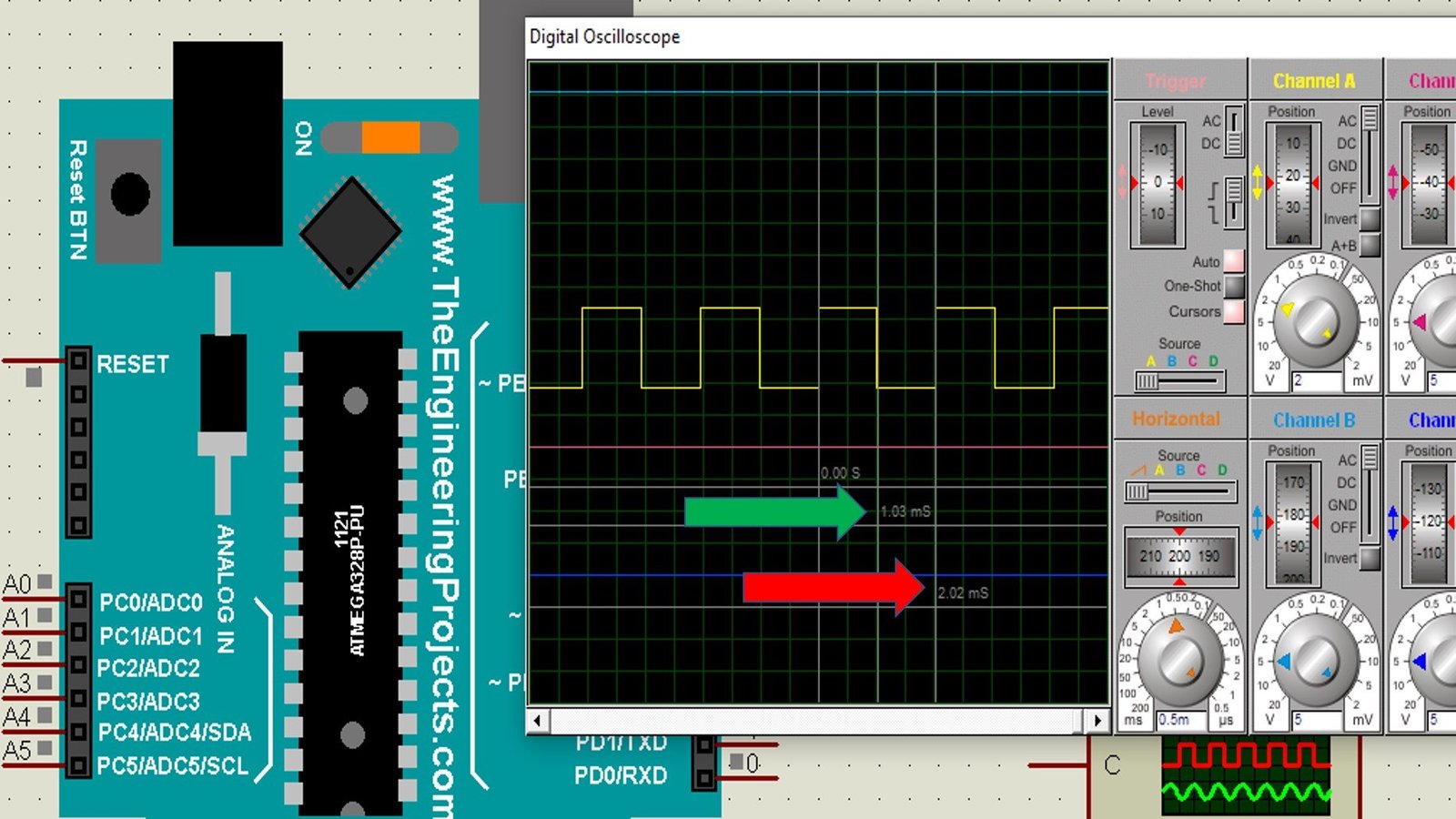
The following code generates a fixed frequency and fixed duty cycle waveform on the D3 pin of Arduino Uno. This code generates a 490Hz and 50% duty cycle signal on the D3 pin.
int PWM_Pin = 3; /* give PWM_Pin name to D3 pin */
// Perform initialization inside setup()
void setup()
{
pinMode(PWM_Pin,OUTPUT);  /*declare D3 pin as an output pin */
}
// loop() executes continously
void loop()
{
analogWrite(PWM_Pin,127);  /* Produce 50% duty cycle PWM on D3 */

}
How Code Works?
Here pin3 will generate a PWM with a 50% duty cycle and default frequency of 480Hz as described above.
The mapping between the duty cycle and number 127 can be understood as follows.
The PWM function width parameter read from value 0 to 255, Value 0 will represent completely OFF waveform and 255 represent completely ON Waveform. Hence, the value 127 will give ((127/255) * 100) = 50% duty cycle and a number 64 will give ((64/255) * 100) = 25% duty cycle waveform.
Program Ouput
As you can see in the output diagram below, the time period of the output waveform is almost 2.02ms. The 2.02ms time period is approximately equal to 490Hz frequency. Moreover, on-time of the output signal is almost 1.01ms which is 50% of the total width of the signal.
How to Set Arduino PWM Frequency?
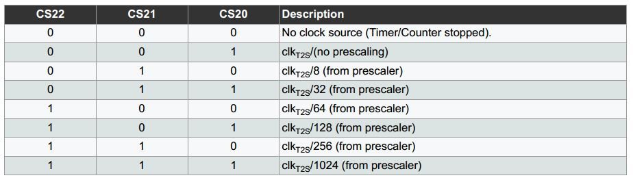
The frequency of a PWM signal is controlled by the clock rate of the counter. The speed of the counter clock is obtained by dividing system clock speed with pre-scaler value. The value of the pre-scaler consists of 3 bits and is stored in the three least significant bits of the timer/counter register. These 3 bits of pre-scaler are denoted by CS02, CS01, and CS00.
There are 3 counter/timer registers in which pre-scaler bits are set and these are named TCCR0B, TCCR1B, and TCCR2B. Arduino pin 5 and 6 are controlled by register TCCR0B, pin 9 and 10 are controlled by TCCR1B and pin 11 and 3 are controlled by TCCR2B. So pin 5 and pin 6 can be set to one frequency, pin 9 and 10 can be set to another different frequency and pin 11 and pin 3 can be set to another different frequency.
Base PWM Frequency
The base frequency of microcontroller in Arduino UNO is defined as
- 31250Hz for Pin 3, 9, 10, 11
- 62500Hz for Pin 5 and 6
To get a waveform of some other frequency than the base frequency; we divide the base frequency by the factor we want to decrease the frequency of the waveform
- Allowed Divisor for pin 3 and 11 are 1, 8, 32, 64, 128, 256, 1024.
- Allowed Divisor for pin 5, 6, 9, and 10 are 1, 8, 64, 256, 1024.
The following code generates the frequency of 30.64 Hz at pin 3 with a 25% duty cycle.
int PWM_Pin = 3; /* give PWM_Pin name to D3 pin */
// Perform initialization inside setup()
void setup()
{
pinMode(PWM_Pin,OUTPUT);  /*declare D3 pin as an output pin */
TCCR2B = TCCR2B & B11111000 | B00000111;
 /*set 30.64Hz Frequency */
}
void loop()
{
analogWrite(PWM_Pin,64);
TCCR2B = TCCR2B & B11111000 | B00000111;
}
The following table can be consulted to choose which bits to be set high for a specific divisor for register TCCR2B.
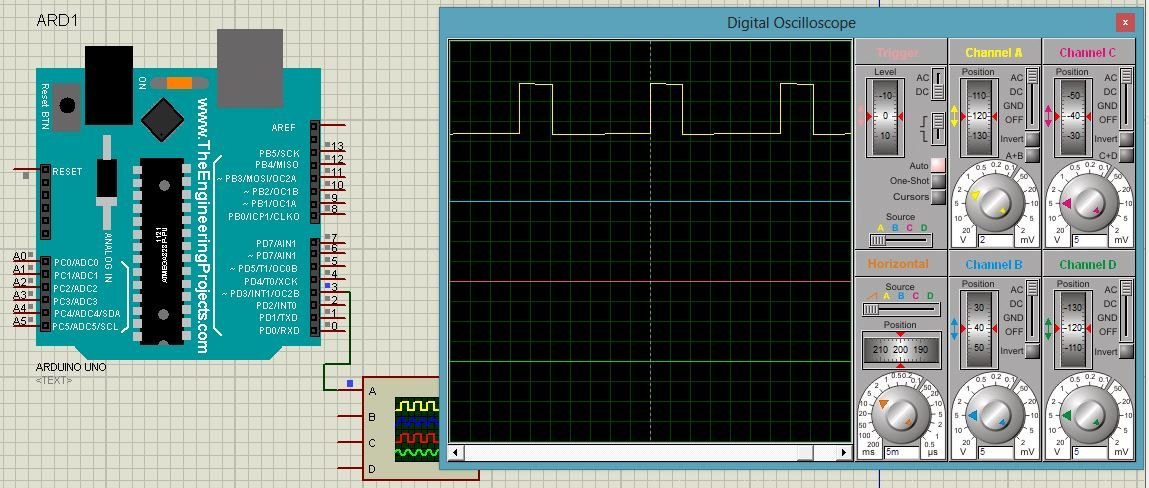
The below figure shows the result of the Proteus simulation for the above code. This picture depicts the duty cycle of 25% and the frequency of almost 30Hz.
Variable Frequency PWM Arduino
In this example, we will control the output frequency of waveform between 10 Hz and 100 Hz at pin 9 with the help of a potentiometer at Analog Pin A0.
Calculate Required Frequency for PWM
The following formula determines the value be entered in the register ICR1 for a particular frequency.
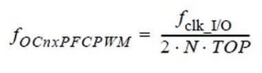
Here
- Fclk_IO = Frequency of microcontroller (For Arduino UNO 16 MHz)
- N = Prescaler
- TOP(ICR1) = Value to be entered in ICR1 Register
- FoCnxPFCPWM = Output frequency of waveform
Therefore, to get a frequency of 100Hz with a pre-scaler value of 8; the value to be entered in the ICR1 register is 10000.
Variable Frequency Arduino Code
Now let’ see a code to generate variable frequency PWM using Arduino D9 pin.
int outputpin=9; // define name for D9 pinPin9 has been defined as an output pin and to activate Fast PWM mode of microcontroller COM1A1 and COM1B1 has been set high in register TCCR1A as given in below figure.

void setup()
{
pinMode(outputpin, OUTPUT);

TCCR1A=_BV(COM1A1)|_BV(COM1B1);
TCCR1B=_BV(WGM13)|_BV(CS11);
}
After this WGM13 bit has been set high so that PWM, Phase, and Frequency correction mode gets activated. CS11 bit has also been set High for selecting a pre-scale value of 8 in register TCCR1B as given in the below figure.
Inside the loop() function, the value of OCR1A is being calculated stepwise according to the required frequency formula given above. After that, the analog pin A0 is read. The analogRead() function reads 1023 when voltage is 5V at the analog pin. Similarly, analogRead() functions reads 0 when voltage is 0V. 0.0113 is a factor that restricts the count variable in the range of 10000 to 100000 which results in a frequency range of 10 Hz to 100Hz.
The potentiometer which connects with analog channel zero (A0) of Arduino is used to control set the frequency of the PWM signal. The value of frequency gets updated on the PWM pin after every one second.
void loop()
{
float frequency=0;
float count=10000;
float count2=0;
float readinput=0;

while(1)
{
ICR1=count;
count2=2*8*count;
frequency= int(16000000/count2);
OCR1A=int(count/2);

count=10000;
readinput=analogRead(A0);
readinput=(readinput/0.0113);
count=count+readinput;

if(count>=100000)
{
count=10000;
}
delay(1000);
}
}
Complete Code
int outputpin=9; /* Assign symbolic name outputpin to D9 PWM pin of Arduino */
/* Perform initialization and declarations inside setup() */
void setup()
{
pinMode(outputpin, OUTPUT); /* set as a output put */
TCCR1A=_BV(COM1A1)|_BV(COM1B1); /* set Fast PWM Mode */
TCCR1B=_BV(WGM13)|_BV(CS11); /* Activate PWM Phase, frequency correction Mode */
}
void loop()
{
float frequency=0; /* initially set frequency to zero */
float count=10000;
float count2=0;
float readinput=0;
while(1)
{
ICR1=count;
count2=2*8*count;
frequency= int(16000000/count2);
OCR1A=int(count/2);
count=10000;
readinput=analogRead(A0);
readinput=(readinput/0.0113);
count=count+readinput;
if(count>=100000)
{
count=10000;
}
delay(1000);
}
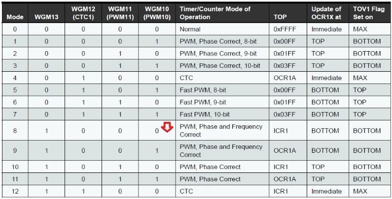
}Proteus Simulation Output

Variable Duty Cycle PWM Arduino
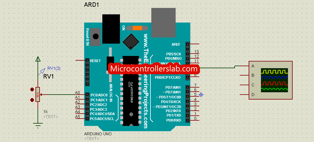
In this section, we will learn to generate variable duty cycle PWM. We will use D10 pin of Arduino to get output signal. To control duty cycle, we will use a potentiometer with analog channel zero of Arduino. In other words, we will map the digital value measured with analogRead() function into duty cycle.
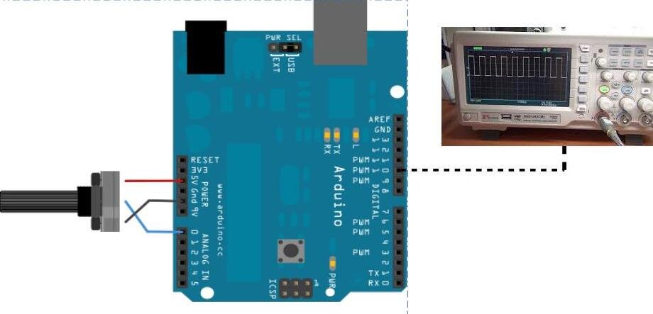
Connection Diagram
Make connections with Arduino and POT according to this schematic diagram. Also, connect an oscilloscope to D10 of Arduino.
Arduino Code
The following code can be used to generate the PWM of the variable duty cycle. Here analog pin A0 reads the voltage from A0 pin and this is translated into 0 to 1023 number. To generate PWM at digital pin we need to convert these numbers in the range of 0 to 255. This has been achieved using the map function.
Two variables have been defined here named as “a” and “b”
int a;
int b;
int pwm_pin = 10;
PWM Pin 10 has been set as an output pin and analog pin A0 has been set as an input pin.
void setup()
{
pinMode(pwm_pin,OUTPUT); /* set pin 10 as a output pin */
pinMode(A0,INPUT); /* ser pin A0 as a input pin */
}
Analog pin A0 is read and the value is stored in “a”. Then mapping of pin A0 and Pin 9 has been performed and anlogWrite() function has been used to generate PWM with duty cycle based on the value of b.
a=analogRead(A0);/* take analog sample from A0 and store result in variable 'a'*/
b= map(a,0,1023,0,255); /* map the digital value to duty cycle range 0-255 */
analogWrite(pwm_pin,b); /* generate pwm signal on pin10 with duty cycle value of b */
Complete Code
This code generates 0-100% variable duty cycle with the default frequency of D10 pin of Arduino.
/*two interger type variables to store digital value and duty cycle value */
int a;
int b;
int pwm_pin = 10;
void setup()
{
pinMode(pwm_pin,OUTPUT); /* set pin 10 as a output pin */
pinMode(A0,INPUT); /* ser pin A0 as a input pin */
}
void loop()
{
a=analogRead(A0);/* take analog sample from A0 and store result in variable 'a'*/
b= map(a,0,1023,0,255); /* map the digital value to duty cycle range 0-255 */
analogWrite(pwm_pin,b); /* generate pwm signal on pin10 with duty cycle value of b */
}
The animation given below shows Proteus simulation for variable duty cycle PWM signal from Arduino pin D10.
Related Tutorials:
bro how to vary frequency from 0 to 800Hz with also varying dutycycle .plz post the code and explain it.
did you ever get the answer to your question because I have a similar requirement.
Hello, is it possible to set the frequency at 90hZ and vary the duty cycle?